
Related Manuals for CAME ZL60


Summary of Contents for CAME ZL60
- Page 1 QUADRO COMANDO FA01040M04 PER MOTORIDUTTORI A 24 V IT Italiano EN English FR Français ZL60 RU Pусский MANUALE DI INSTALLAZIONE...
- Page 2 è stato espressamente studiato. Ogni altro uso è da considerarsi pericoloso. CAME S.p.A. non è responsabile per eventuali danni causati da usi impropri, erronei ed irragionevoli. • Prima di installare l’automazione verifi care che la parte...
- Page 3 devono passare attraverso apposite tubazioni o canaline al fi ne di garantire un’adeguata protezione contro il danneggiamento meccanico e non devono entrare in contatto con parti che possono riscaldarsi durante l’uso. • Prevedere nella rete di alimentazione e conformemente alle regole di installazione, un adeguato dispositivo di disconnessione onnipolare che consenta la disconnessione completa nelle condizioni della categoria di sovratensione III.
- Page 4 Destinazione d'uso Uso residenziale e condominiale. Ogni installazione e uso diff ormi da quanto indicato nel seguente manuale sono da considerarsi vietate. Dati tecnici Tipo ZL60 Grado di protezione (IP) Alimentazione (V - 50/60 Hz) 230 AC Alimentazione motore (V)
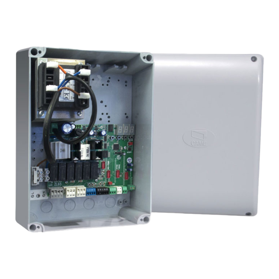
- Page 5 Descrizione delle parti 1. Fusibile linea 10. Connettore scheda AF 2. Morsettiera alimentazione rete 11. Morsettiera antenna 3. Morsettiere trasformatore 12. Morsettiera dispositivi di sicurezza 4. Trasformatore 13. Connettore scheda R800 5. Morsettiera modulo RGP1 14. Morsettiere dispositivi di comando 6.
- Page 6 INDICAZIONI GENERALI PER L'INSTALLAZIONE ⚠ L’installazione deve essere effettuata da personale qualificato ed esperto e nel pieno rispetto delle normative vigenti. ⚠ Attenzione! Prima di intervenire sul quadro comando, togliere la tensione di linea e, se presenti, scollegare le batterie. Tipi di cavi e spessori minimi lunghezza cavo Collegamento...
- Page 7 INSTALLAZIONE Fissaggio del quadro comando Fissare la base del quadro in una zona protetta; si consiglia di usare viti di diametro max. 6 mm testa bombata con impronta a croce. Forare sui fori presfondati. I fori presfondati hanno diametri differenti: 23, 29 e 37 mm. ⚠ ...
- Page 8 Collegamento motoriduttore con Encoder Applicare all'interno del quadro comando una ferrite (non fornita, tipo FAIR- RITE materiale 31 mod. 2631102002) sui cavi dei motoriduttori. M1 N1 ENC1 M2 N2 ENC2 M2 chiude per secondo M1 apre per secondo Dispositivo di segnalazione 10 11 E Uscita collegamento lampeggiatore o lampada ciclo.
- Page 9 Dispositivi di sicurezza 1 2 3P 7 10 TS 2 C1 CX Collegamento fotocellule (contatto NC), vedi programmazione delle funzioni. Collegamento fotocellule in riapertura durante la chiusura (contatto NC), vedi programmazione delle funzioni. Collegamento di sicurezza delle fotocellule (test servizi). Fotocellule Configurare il contatto C1 o CX (NC), ingresso per dispositivi di sicurezza tipo 10 TS 2 C1 CX...
- Page 10 Menu funzioni Iniziare la programmazione eseguendo per prime le funzioni di: Tipo motore, Numero motori, STOP TOTALE e Auto-apprendimento. Descrizione delle funzioni Tipo motore Di default, il quadro gestisce i motoriduttori della serie OPP001 e FTL20DGC. Per gestire i motoriduttori della serie OPS001, BXL04AGS. selezionare i DIP come indicato e premere il tasto PROG sulla scheda.
- Page 11 Rilevazione ostacolo a motore fermo Di default, la funzione è abilitata. Per disabilitarla: selezionare i DIP come indicato e premere il tasto PROG sulla scheda. Il LED lampeggia e il buzzer suona 2 volte. Per ritornare all'impostazione di default, premere di nuovo PROG. Il LED rimane acceso e il buzzer suona per 1 s.
- Page 12 Test Servizi Di default, la funzione è disabilitata. Per abilitarla: Selezionare i DIP come indicato e premere il tasto PROG sulla scheda. Il LED rimane acceso e il buzzer suona per 1 s. Per ritornare all'impostazione di default, premere di nuovo PROG. Il LED lampeggia e il buzzer suona 2 volte. Azione mantenuta da pulsante Di default, la funzione è...
- Page 13 Auto-apprendimento della corsa Con Encoder abilitato (impostazione di default) - Selezionare i DIP e premere il tasto PROG sulla scheda come indicato sulla programmazione delle funzioni. L'automazione eseguirà una serie di manovre per la determinazione dei punti di inizio rallentamenti e dei finecorsa: = 25% dell'area di movimento a velocità...
- Page 14 Regolazioni delle funzioni A.C.T. APP./O.T. 2M DELAY SPEED SLOW SENS. Trimmer Descrizione delle funzioni Tempo chiusura automatica Regola il tempo di attesa del cancello in posizione di apertura. Trascorso questo tempo, viene effettuata A.C.T. automaticamente una manovra di chiusura. Il tempo di attesa può essere regolato da 1 a 180 secondi. Punto di accostamento (Encoder abilitato) o tempo lavoro (Encoder disabilitato) Regola il punto di inizio dell’accostamento dei motori prima del fi...
- Page 15 OPERAZIONI FINALI Fissaggio del coperchio Terminati i collegamenti elettrici e la messa in funzione, inserire il coperchio e fissarlo con le viti fornite. RISOLUZIONE DEI PROBLEMI SEGNALAZIONI POSSIBILI CAUSE SOLUZIONI Il LED PROG lampeggia e • La scheda elettronica non •...
- Page 16 CAME S.p.A. Via Martiri Della Libertà, 15 31030 Dosson di Casier - Treviso - Italy tel. (+39) 0422 4940 - fax. (+39) 0422 4941...
- Page 17 CONTROL PANEL FA01040-EN FOR 24 V GEARMOTORS ZL60 EN English INSTALLATION MANUAL...
- Page 18 . • This product should only be used for the purpose for which it was explicitly designed. Any other use is dangerous. CAME S.p.A. is not liable for any damage caused by improper, wrongful and unreasonable use. • Before installing the control panel, make sure that the guided part is in proper mechanical order, that it opens and closes properly and that it is balanced - otherwise, do not continue until you have fi...
- Page 19 other devices in the system. Remember to hand over to the end users all the operating manuals of the products that make up the fi nal machinery.
- Page 20 For private homes and apartment buildings. Do not install of use this device in any way, except as specifi ed in this manual. Technical data Type ZL60 Protection rating (IP) Power supply (V - 50/60 Hz) 230 AC Input voltage motor (V)
- Page 21 Description of parts 1. Line fuse 10. AF card connector 2. Power supply terminals 11. Antenna terminals 3. Transformer terminal 12. Safety-device terminals 4. Transformer 13. R800 card connector 5. RGP1 module terminal 14. Control-device terminals 6. Trimmer 15. Keypad selector terminal 7.
- Page 22 GENERAL INSTRUCTIONS FOR INSTALLING ⚠ Only skilled, qualified staff must install this product. ⚠ Caution! Before working on the control panel, cut off the mains power supply and remove any batteries. Cable types and minimum thicknesses cable length Connection < 20 m 20 <...
- Page 23 INSTALLATION Fastening the control panel Fasten the control panel in a protected area; use rounded cross head screws with maximum 6 mm diameter. maximum 6 mm diameter. Perforate the punched holes. The holes have different diameters: 23, 29 and 37 mm. ⚠ ...
- Page 24 Connecting the gearmotor to the Encoder Apply a ferrite to the gearmotor cables inside of the control panel. It should be a FAIR-RITE type material 31 mod. 2631102002, and is not supplied. M1 N1 ENC1 M2 N2 ENC2 M2 closes second M1 opens second Warning device 10 11 E...
- Page 25 Safety devices 1 2 3P 7 10 TS 2 C1 CX Photocells connection (NC contact), see the functions programming section. Reopening during closing photocells connection (NC contact) see functions programming. Photocells safety connection (services test) Photocells Configure contact C1 or CX (NC), input for safety devices such as photocells. 10 TS 2 C1 CX See functions programming of input C1 or CX in: - C1 reopening while closing.
- Page 26 Functions menu First of all, program the following functions first: Type of motor, Number of motors, TOTAL STOP and Self-learning. DIP-SWITCH Description of functions Motor type By default,the control panel controls OPP001 and FTL20DGC-series gearmotors. For controlling OPS001, BXL04AGS-series gearmotors. select the DIP-switches as shown and press the PROG button on the control board.
- Page 27 Partial opening or pedestrian opening (contact 2-3P) By default, the opening is set to pedestrian mode. To enable in partial opening: Select the DIP-switches as shown and press the PROG button on the control board. The LED stays on and the buzzer sounds for one second.
- Page 28 Saving the trimmer value Use the trimmers to set the automatic closing time (A.C.T.), the opening and closing latching points, the second motor's closing-delay speed, the slow-down speed (SDS) and the sensitivity (SENS.). To save the values: select the DIP-switches as shown and press the PROG button on the control board. The PRG LED stays lit and the buzzer sounds off for one second.
- Page 29 Auto-learning of the gate-leaf travel With the Encoder enabled (the default setting) - Select the Dip-switch and press the PROG button the control board as explained in the functions programming section. The operator will perform a series of maneuvers to establish the starting slow-down and limit-switch points.
- Page 30 Adjusting the functions A.C.T. APP./O.T. 2M DELAY SPEED SLOW SENS. Trimmer Description of functions Automatic Closing Time A.C.T. It sets the open gate's waiting time. Once this time elapses, the shutter automatically closes. The wait time can be adjusted to between 1 and 180 seconds. Latching point - with Encoder enabled - or operating time - with Encoder disabled.
- Page 31 FINAL OPERATIONS Fastening the cover Once finished with the electrical connections and powering up, fit the cover and secure it using the supplied screws. TROUBLESHOOTING ALERTS POSSIBLE CAUSES FIXES The PROG LED flashes • The control board does not work •...
- Page 32 CAME S.p.A. Via Martiri Della Libertà, 15 31030 Dosson di Casier - Treviso - Italy tel. (+39) 0422 4940 - fax. (+39) 0422 4941...
- Page 33 ARMOIRE DE COMMANDE FA01040-FR POUR MOTORÉDUCTEURS 24 V ZL60 MANUEL D'INSTALLATION FR Français...
- Page 34 être exécutées que par du personnel qualifi é. • Ce produit ne devra être destiné qu'à l'utilisation pour laquelle il a été expressément conçu. Toute autre utilisation est à considérer comme dangereuse. CAME S.p.A. décline toute responsabilité en cas de dommages provoqués par des utilisations impropres, incorrectes ou déraisonnables.
- Page 35 électriques doivent passer à travers des tuyaux ou des conduites spécifi ques afi n de garantir une protection adéquate contre toute détérioration mécanique et ne doivent pas entrer en contact avec des parties pouvant devenir chaudes durant l’utilisation. • Prévoir sur le réseau d'alimentation, conformément aux règles d'installation, un dispositif de déconnexion omnipolaire spécifi...
- Page 36 Utilisation prévue Usage résidentiel et collectif. Toute installation et toute utilisation autres que celles qui sont indiquées dans ce manuel sont interdites. Données techniques Type ZL60 Degré de protection (IP) Alimentation (V - 50/60 Hz) 230 AC Alimentation moteur (V)
- Page 37 Description des parties 1. Fusible de ligne 11. Barrette antenne 2. Bornier d'alimentation réseau 12. Bornier dispositifs de sécurité 3. Borniers transformateur 13. Connecteur carte R800 4. Transformateur 14. Borniers dispositifs de commande 5. Bornier module RGP1 15. Bornier clavier à code 6.
- Page 38 INSTRUCTIONS GÉNÉRALES POUR L'INSTALLATION ⚠ L’installation doit être effectuée par du personnel qualifié et dans le plein respect des normes en vigueur. ⚠ Attention ! Avant d'intervenir sur l'armoire de commande, mettre hors tension et déconnecter les éventuelles batteries. Types de câbles et épaisseurs minimum longueur câble Connexion <...
- Page 39 INSTALLATION Fixation de l'armoire de commande 1) Fixer la base du tableau dans une zone protégée ; il est conseillé d'utiliser des vis d'un diamètre max. de 6 mm avec tête bombée cruciforme. Percer les trous préforés. Les trous préforés présentent des diamètres différents : 23, 29 et 37 mm. ⚠ ...
- Page 40 Connexion motoréducteur avec encodeur Appliquer, à l'intérieur de l'armoire de commande, une ferrite (non fournie, type FAIR-RITE matériau 31 mod. 2631102002) sur les câbles des motoréducteurs. M1 N1 ENC1 M2 N2 ENC2 M2 ferme par seconde M1 ouvre par seconde Dispositif de signalisation 10 11 E Sortie connexion clignotant ou lampe cycle.
- Page 41 Dispositifs de sécurité 1 2 3P 7 10 TS 2 C1 CX Connexion des photocellules (contact NF), voir programmation des fonctions. Connexion des photocellules en modalité réouverture durant la fermeture (contact NF), voir programmation des fonctions. Connexion de sécurité des photocellules (test services). Photocellules Configurer le contact C1 ou CX (NF), entrée pour dispositifs de sécurité...
- Page 42 Menu fonctions Commencer la programmation par les fonctions suivantes : Type moteur, Nombre moteurs, ARRÊT TOTAL et Autoapprentissage. Description des fonctions Type moteur L’armoire gère par défaut les motoréducteurs de la série OPP001 et FTL20DGC. Pour gérer les motoréducteurs de la série OPS001, BXL04AGS. sélectionner les commutateurs DIP comme indiqué...
- Page 43 Ouverture partielle ou piétonne par bouton (contact 2-3P) La fonction est, par défaut, en mode ouverture piétonne. Pour activer le mode ouverture partielle : sélectionner les commutateurs DIP comme indiqué et appuyer sur la touche PROG sur la carte. Le voyant reste allumé...
- Page 44 Mémorisation valeur trimmer Régler, à l'aide des trimmers, le temps de fermeture automatique (A.C.T.), le point de rapprochement de l'ouverture et de la fermeture, le temps de retard du deuxième moteur en phase de fermeture, la vitesse de marche, la vitesse de ralentissement (SP.RAL.) et la sensibilité (SENS.). Pour mémoriser les valeurs : sélectionner les commutateurs DIP comme indiqué...
- Page 45 Auto-apprentissage de la course Avec encodeur activé (configuration par défaut) - Sélectionner les micro-interrupteurs DIP et appuyer sur la touche PROG sur la carte comme indiqué sur la programmation des fonctions. L’automatisme effectuera une série de manœuvres pour permettre l'identification des points de ralentissement initial et de fin de course : = 25% de la zone de mouvement au ralenti en phase d’ouverture.
- Page 46 Réglages des fonctions A.C.T. APP./O.T. 2M DELAY SPEED SLOW SENS. Trimmers Description des fonctions Temps de fermeture automatique Permet de régler le délai d'attente du portail en position d'ouverture. Après écoulement de ce délai, une manœuvre de fermeture est automatiquement effectuée. Le temps d'attente peut être réglé...
- Page 47 OPÉRATIONS FINALES Fixation du couvercle Au terme des branchements électriques et de la mise en fonction, mettre le couvercle et le fixer à l'aide des vis fournies. RÉSOLUTION DES PROBLÈMES SIGNALISATIONS CAUSES POSSIBLES SOLUTIONS La LED PROG clignote et • La carte électronique ne •...
- Page 48 CAME S.p.A. Via Martiri Della Libertà, 15 31030 Dosson di Casier - Treviso - Italy tel. (+39) 0422 4940 - fax. (+39) 0422 4941...
- Page 49 БЛОК УПРАВЛЕНИЯ FA01040-RU ЭЛЕКТРОПРИВОДАМИ 24 В ZL60 РУКОВОДСТВО ПО УСТАНОВКЕ RU Русский...
- Page 50 должны выполняться квалифицированным и опытным персоналом. • Это изделие должно использоваться исключительно по назначению. Любое другое применение рассматривается как опасное. CAME S.p.A. не несет никакой ответственности за ущерб, нанесенный неправильным, ошибочным или небрежным использованием изделия. • Перед установкой автоматики, убедитесь в том, что подвижное...
- Page 51 использование неоригинальных изделий, что среди прочего подразумевает снятие изделия с гарантии. • Все устройства управления в режиме «Присутствия оператора», подключенные к блоку управления, должны располагаться в местах, удаленных от подвижных механизмов, но обеспечивающих хороший обзор зоны движения автоматики. • Убедитесь в том, что автоматика была правильно отрегулирована, и что...
- Page 52 Применение в частных жилых домах и комплексах. Запрещается использовать устройство не по назначению и устанавливать его методами, отличными от описанных в настоящей инструкции. Технические характеристики Модель ZL60 Класс защиты (IP) Напряжение электропитания (В, 50/60 Гц) ~230 Электропитание двигателя (В) Потребление в режиме ожидания (Вт) Потребление...
- Page 53 Основные компоненты 1. Входной предохранитель безопасности 2. Контакты сетевого электропитания 13. Разъем для платы R800 3. Контакты подключения трансформатора 14. Контакты подключения устройств 4. Трансформатор управления 5. Контакты подключения модуля RGP1 15. Контакты подключения кодонаборной 6. Регулировки клавиатуры 7. Кнопка программирования 16.
- Page 54 ОБЩИЕ ИНСТРУКЦИИ ПО МОНТАЖУ ⚠ Монтаж должен производиться квалифицированным персоналом в полном соответствии с требованиями действующих норм безопасности. ⚠ Внимание! Перед началом работ по эксплуатации, ремонту, настройке и регулировке блока управления отключите сетевое электропитание и/или вытащите аккумуляторы. Тип и сечение кабелей Длина...
- Page 55 УСТАНОВКА Монтаж блока управления Установите основание блока управления в защищенном от повреждений месте. Рекомендуется использовать винты с выпуклой головкой под крест. Рассверлите предварительно размеченные отверстия. Отверстия имеют различный диаметр: 23, 29 и 37 мм. ⚠ Будьте предельно осторожны, чтобы не повредить плату блока управления! ...
- Page 56 Подключение привода с энкодером В блоке управления на провода приводов установите феррит (не входит в комплект поставки, тип FAIR- RITE, материал 31 мод. 2631102002). M1 N1 ENC1 M2 N2 ENC2 M2 закрывается вторым M1 открывается вторым Устройство сигнализации 10 11 E Контакты...
- Page 57 Устройства безопасности 1 2 3P 7 10 TS 2 C1 CX Подключение фотоэлементов (нормально-замкнутые контакты), см. раздел «Программирование функций». Подключение фотоэлементов для выполнения функции «Открывание в режиме закрывания» (нормально-замкнутые контакты), см. раздел «Программирование функций». Подключение для самодиагностики фотоэлементов (самодиагностика устройств безопасности). Фотоэлементы...
- Page 58 Меню «Функции» Рекомендуется начать процедуру программирования со следующих функций: «Модель двигателя», «Количество двигателей», «СТОП» и «Автоматическое определение». DIP- Описание функций и режимов работы переключатели Модель привода По умолчанию блок управления управляет приводами серий OPP001 и FTL20DGC. Для управления приводами серий OPS001, BXL04AGS: установите...
- Page 59 «ОТКРЫТЬ-ЗАКРЫТЬ-ИЗМЕНИТЬ НАПРАВЛЕНИЕ» или «ОТКРЫТЬ-СТОП-ЗАКРЫТЬ-СТОП» с помощью кнопки (контакты 2-7) По умолчанию установлена функция «ОТКРЫТЬ-ЗАКРЫТЬ-ИЗМЕНИТЬ НАПРАВЛЕНИЕ». Чтобы активировать «ОТКРЫТЬ-СТОП-ЗАКРЫТЬ-СТОП»: установите DIP-переключатели, как показано на рисунке, и нажмите кнопку PROG на плате управления. Светодиодный индикатор загорится ровным светом, а зуммер издаст звуковой сигнал длительностью 1 с. Чтобы...
- Page 60 Дожим при закрывании По умолчанию функция отключена. Для ее активации: установите DIP-переключатели, как показано на рисунке, и нажмите кнопку PROG на плате управления. Светодиодный индикатор PRG загорится ровным светом, и зуммер издаст звуковой сигнал длительностью 1 с. Для восстановления заводских настроек снова нажмите кнопку PROG. Светодиодный индикатор начнет мигать, и зуммер...
- Page 61 Сброс параметров Установите DIP-переключатели, как показано на рисунке, нажмите кнопку PROG на плате управления и удерживайте ее в течение 5 с. По завершении удаления данных светодиодный индикатор PRG загорится ровным светом, а зуммер издаст звуковой сигнал длительностью 1 с. С помощью данной функции можно восстановить удаленные данные пользователей. Автоматическое...
- Page 62 Регулировка функций с помощью триммеров A.C.T. APP./O.T. 2M DELAY SPEED SLOW SENS. Регулировки Описание функций и режимов работы Время автоматического закрывания Регулирует время ожидания ворот в открытом положении. По истечении заданного времени A.C.T. происходит автоматическое закрывание. Время автоматического закрывания может составлять от 1 до 180 секунд. Точка...
- Page 63 ЗАКЛЮЧИТЕЛЬНЫЕ РАБОТЫ Крепление крышки После выполнения всех электрических подключений и подготовки системы к работе установите крышку и прикрепите ее прилагаемыми винтами. УСТРАНЕНИЕ НЕИСПРАВНОСТЕЙ НЕИСПРАВНОСТЬ ВОЗМОЖНАЯ ПРИЧИНА СПОСОБЫ УСТРАНЕНИЯ Светодиодный • Блок управления не работает. • Обратитесь к установщику. индикатор PROG мигает, а...
- Page 64 CAME S.p.A. Via Martiri Della Libertà, 15 31030 Dosson di Casier - Treviso - Italy tel. (+39) 0422 4940 - fax. (+39) 0422 4941...
Need help?
Do you have a question about the ZL60 and is the answer not in the manual?
Questions and answers