CAME ZLX24SA Installation Manual
Hide thumbs
Also See for ZLX24SA:
- Installation manual (41 pages) ,
- Installation manual (64 pages) ,
- Installation manual (60 pages)
Advertisement
Quick Links
Advertisement

Subscribe to Our Youtube Channel
Related Manuals for CAME ZLX24SA


Summary of Contents for CAME ZLX24SA
- Page 1 FA01412-EN ZLX24SA ZLX24SR INSTALLATION MANUAL English...
- Page 2 fi nal installation to comply with the Machinery Directive (2006/42/EC) and with the reference harmonised technical standards are specifi ed in the general CAME product catalogue or on the website www.came.com. • Check that the temperature ranges given are suitable for the installation site.
- Page 3 • The electrical cables must pass through special pipes, ducts and cable glands in order to guarantee adequate protection against mechanical damage. • The electrical cables must not touch any parts that may overheat during use (such as the motor and transformer). • Before installation, check that the guided part is in good mechanical condition, and that it opens and closes correctly.
- Page 4 UNI EN ISO 14001 standard to ensure that the environment is respected and safeguarded. Please continue safeguarding the environment. At CAME we consider it one of the fundamentals of our operating and market strategies. Simply follow these brief disposal guidelines: DISPOSING OF THE PACKAGING The packaging materials (cardboard, plastic, etc.) can be disposed of easily as solid urban waste, separated for recycling.
- Page 5 Description 801QA-0060 ZLX24SA - Multifunction control panel, with 230 VAC power supply, for 24 V swing gates with two leaves, with graphic programming display and signalling, safety device self-diagnostics, adaptive speed and torque technology, BUS CXN, 4 safety inputs and memory space for up to 1000 users.
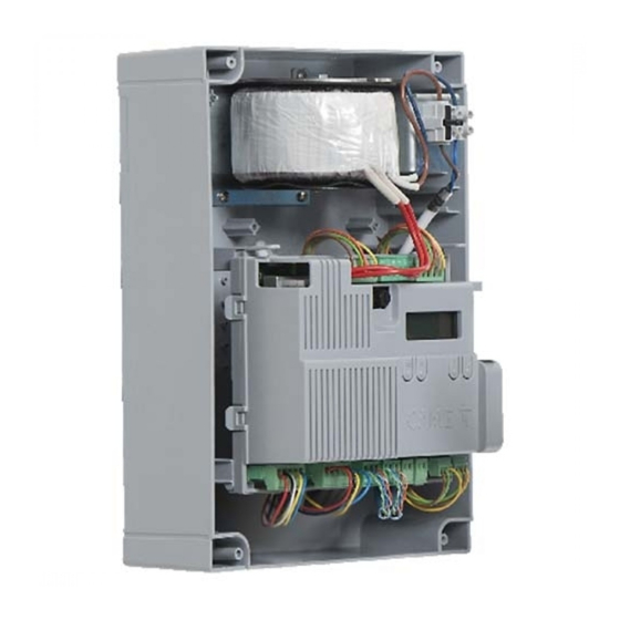
- Page 6 Terminal boards for connecting micro limit switches (NC Terminal board for B1-B2 output contact) Memory Roll card connector Terminal board for connecting the gearmotor with Connector for CAME KEY encoder or with slowdown switch and electric lock Display Accessories fuse Programming buttons...
- Page 7 Optional accessories RGSM001 module (806SA-0010) RLB battery charger board (002RLB) SMA module (009SMA) ZLX24S can use two diff erent types of emergency battery, installed on an external panel: - Two 7Ah batteries (846XG-0030) to manage all motors required for the control panel. - Two 2.3Ah batteries (846XG-0020) to manage motors with low current draw.
- Page 8 Size Cable types and minimum thicknesses Cable length (m) up to 20 from 20 to 30 Power supply 230 V AC 3G x 1.5 mm² 3G x 2.5 mm² 24 V AC/DC fl ashing beacon 2 x 0.5 mm² 2 x 0.5 mm² TX Photocells 2 x 0.5 mm²...
- Page 9 INSTALLATION Preparing the control panel...
- Page 10 Fastening the control panel DIN rail Standard...
- Page 11 ELECTRICAL CONNECTIONS Preparing the electrical cables Connect all wires and cables in compliance with the law. Use cable glands to connect the devices to the control panel. One of these must be used exclusively for the power supply cable. Power supply Connecting to the mains (230/120 V AC - 50/60 Hz) F - Line fuse L - Phase...
- Page 12 For subsequent connections, reposition the control board and remove the board protection. Power supply output for accessories The output normally delivers 24 V AC. The output delivers 24 V DC (10+, 11-) when the batteries start operating, if they are installed. The sum of the power draw for the connected accessories must not exceed 50 W.
- Page 13 Accessories B1 - B2 24 AC/DC 15 DC Do not connect anything other than CAME BUS accessories. Gearmotors M1 =Gearmotor delayed while opening M2 =Gearmotor delayed while closing Where there is only one gearmotor in the system, make the electrical connections on the gearmotor (M2).
- Page 14 Gearmotor with encoder E1 - E2 - M1 N1 ENC1 EB1+VB M2 N2 ENC2 EB2+VB FC2 FA2 F FC1 FA1 F FROG-A24E / FERNI / FERNI-V M1 N1 ENC1 EB1+VB M2 N2 ENC2 EB2+VB ATS / AXO / FTX / FAST-70 / AMICO / AXI...
- Page 15 M1 N1 ENC1 EB1+VB M2 N2 ENC2 EB2+VB STYLO-RME M1 N1 ENC1 EB1+VB M2 N2 ENC2 EB2+VB STYLO-ME...
- Page 16 Gearmotors with slowdown switches FC1 FA1 F FC2 FA2 F M1 N1 ENC1 EB1+VB M2 N2 ENC2 EB2+VB A3024N / A5024N E1 - E2 - M2 N2 ENC2 EB2+VB M1 N1 ENC1 EB1+VB FC1 FA1 F FC2 FA2 F FROG-A24 Gearmotors without encoder M1 N1 ENC1 EB1+VB M2 N2 ENC2 EB2+VB...
- Page 17 Devices with BUS CXN system The CXN CAME system is a two-wire non-polarised communication BUS which allows you to connect up all compatible CAME devices. Connection to the BUS can be in a chain, star or mixed formation. Once the system has been wired, and after having set the address on each device, the function of each accessory can be confi...
- Page 18 Command and control devices STOP button (NC contact) Stop the gate and exclude automatic closing. Use a control device to resume movement. When the contact is being used, it must be activated during programming. Control device (NO contact) OPEN ONLY function When the [HOLD-TO-RUN] function is active, the control device must be connected during OPENING.
- Page 19 Signalling devices Flashing beacon It fl ashes when the operator opens and closes. Additional light It increases the light in the manoeuvring area. See [Additional light] function. Operator status warning light It notifi es the user of the operator status. See [Gate-open warning light] function.
- Page 20 Safety devices During programming, confi gure the type of action that must be performed by the device connected to the input. Connect the safety devices to the CX and/or CY and/or CZ and/or CK inputs. If contacts CX, CY, CZ and CK are not used, they must be deactivated during programming. DELTA photocells DELTA photocells Standard connection...
- Page 21 DXR - DLX photocells DXR - DLX photocells Standard connection Connection with safety test See [Safety devices test] function. 10 TS 2 CX CY CZ CK 10 TS 2 CX CY CZ CK 10 11 E E3 5 10 11 E E3 5 10 11 OUT 10 11 OUT 10 11 SY...
- Page 22 PROGRAMMING Programming button functions ESC button The ESC button is used to perform the operations described below. Exit the menu Delete the changes Go back to the previous screen Stop the operator < > buttons The <> buttons are used to perform the operations described below. Navigate the menu Increase or decrease values ENTER button...
- Page 23 Getting started Once the electrical connections have been made, proceed with commissioning. Only skilled and qualifi ed staff may perform this operation. Make sure that there are no obstacles in the way. Power up the device and begin programming. Start programming with the WIZARD functions. If it is not the fi...
- Page 24 Diagrams showing leaf speed, slowdown and approach points Closing limit-switch Opening speed Opening limit-switch Closing speed Opening slowdown point Opening slowdown speed Closing slowdown point Closing slowdown speed Opening approach point Approach speed (fi xed) Closing approach point Invert-motion zone in case of obstructions Stop-motion zone in case of obstructions Graph showing speed curves during movement, slowdown and approach.
- Page 25 Without using slowdown space (slowdown space = 0) Opening or closing speed Approach speed (fi xed) Obstruction travel sensitivity Opening or closing limit-switch Opening or closing approach point Virtual encoder For gearmotors without an encoder or with the encoder deactivated, travel is managed using a VIRTUAL ENCODER. ALWAYS calibrate the travel, as with motors with an encoder.
- Page 26 Motor type Set the type of gearmotor installed on M1 and M2. If the value set for M1 is diff erent to the value set for M2, only the value for M2 is shown here. Confi guration> Motor type STYLO ME Motor settings STYLO RME FAST-70...
- Page 27 Motor test Check the gate leaves open in the right direction. With the function active, the > key opens the gate leaf connected to M2, and the < key opens the gate leaf connected to M1. The movement continues while the key is pressed or until the end-of-travel limit switch is reached. When the key is released, the movement stops.
- Page 28 Travel AST control Adjust the obstruction detection sensitivity during boom travel (percent). Confi guration> Travel AST control Deactivated (Default) Gate travel settings Maximum thrust and low obstruction sensitivity. Minimum Average Maximum Minimum thrust and high obstruction sensitivity. Customised Customised closing Customised opening The personalised values to be used are expressed as a percentage:...
- Page 29 Closing slowdown point Set the percentage of the total travel to be used for the M1 and M2 closing slowdown. If the value set for M1 is diff erent to the value set for M2, only the value for M2 is shown here. Confi...
- Page 30 Confi gure travel M1 Modify certain parameters previously described for motor M1 only (where diff erent from M2). The menu is not available if “M2” is selected under “Number of motors”. Confi guration> Opening speed See the specifi c parameters for each function. Gate travel settings>...
- Page 31 CX input Associate a function with the CX input. Confi guration> CX input Deactivated (Default) Wired safety devices C1 = Reopen while closing (photocells) C2 = Reclose while opening (photocells) C3 = Partial stop Only with [Automatic close] activated. C4 = Obstacle standby (photocells) C7 = Reopen while closing (sensitive edges) C8 = Reclose while opening (sensitive edges) C13 = Reopen while closing, with immediate stop once...
- Page 32 CZ input Associate a function with the CZ input. Confi guration> CZ input Deactivated (Default) Wired safety devices C1 = Reopen while closing (photocells) C2 = Reclose while opening (photocells) C3 = Partial stop Only with [Automatic close] activated. C4 = Obstacle standby (photocells) C7 = Reopen while closing (sensitive edges) C8 = Reclose while opening (sensitive edges) C13 = Reopen while closing, with immediate stop once...
- Page 33 Safety devices test Check that the photocells connected to the selected inputs are operating correctly, after each opening and closing command. To run the check, the photocells must be connected using the TS terminal as indicated in the “Safety devices” section.
- Page 34 RIO PH T1 Associate one of the available functions with a wireless safety device. The function only appears if the RIO CONN interface board is present. Confi guration> RIO PH T1 Deactivated (Default) RIO safety devices P1 = Reopen while closing. P2 = Reclose while opening.
- Page 35 Hold-to-run With the function active, the operator stops moving (opening or closing) when the control device is released. When the function is active, it excludes all other control devices. Confi guration> Hold-to-run Deactivated (Default) Command inputs Electric lock Associate the electric lock release with a command. Confi...
- Page 36 Automatic closure Set the time before automatic closure is activated, once the opening travel end point has been reached. The function does not work if any of the safety devices are triggered when an obstacle is detected, after a complete stop, during a power outage or if there is an error. Confi...
- Page 37 Additional light Choose the operating mode for the lighting device connected to output E3. Confi guration> Additional light Disabled (Default) Manage lights Cycle lamp The lamp stays on during the manoeuvre. The light remains off if an automatic closing time is not set.
- Page 38 Read data Upload user data, timings and confi gurations to the memory device (memory roll). Confi guration> Read data External memory ON (Run operation) Parameter reset Restore the “Confi guration” menu parameters to factory settings, except for: [motor type], [number of motors], [limit-switch inputs function], [RSE speed] and [CRP address].
- Page 39 Radio decoding Choose the type of radio coding for the transmitters enabled to control the operator. If you choose the type of radio coding for the transmitters [Rolling code] or [TW key block], any transmitters saved previously will be deleted. Manage users Radio decoding All decodings...
- Page 40 Manoeuvre counter View the number of total or partial operator manoeuvres (after maintenance). Information Manoeuvre counter Total manoeuvres Partial manoeuvres Confi gure maintenance Activate a warning to signal that maintenance needs to be performed when the set number of manoeuvres is reached. The signal consists of the message “Maintenance required”...
- Page 41 Create new timer Time one or more types of activation chosen from those available. Timer management Create new timer Use the arrows to choose the desired function. Open / Partial opening / Output B1-B2 Press ENTER to confi rm. Use the arrows to set the start and end time of the function activation.
- Page 42 Forgotten password If you lose the password, you will need to reset the board to its factory settings. See [Factory reset]. Factory reset To restore the electronic board data to factory settings: Disconnect the control board from the power supply. Press and hold the <...
- Page 43 ERROR MESSAGES Motor M1 calibration error Motor M2 calibration error Encoder failure error Service test failure error Operating time error Consecutive obstacles detected during closing Consecutive obstacles detected during opening Maximum number of obstacles Motor supply voltage missing or insuffi cient Incompatible transmitter error Wireless system communication error Wireless system not confi...
- Page 48 CAME S.p.A. Via Martiri della Libertà, 15 31030 Dosson di Casier Treviso - Italy Tel. (+39) 0422 4940 Fax (+39) 0422 4941...
Need help?
Do you have a question about the ZLX24SA and is the answer not in the manual?
Questions and answers