
Related Manuals for CAME ZL60


Summary of Contents for CAME ZL60
- Page 1 QUADRO COMANDO 3 1 9 W7 6 PER MOTORIDUTTORI A 24 V Manuale d’installazione ZL60 Italiano English Français Русский...
-
Page 2: Riferimenti Normativi
Destinazione d'uso Il quadro comando ZL60 è stato progettato per il comando dei motoriduttori CAME per cancelli a battente a uso residenziale o condominiale. Ogni installazione e uso difformi da quanto indicato nel seguente manuale sono da considerarsi vietate. -
Page 3: Dimensioni (Mm)
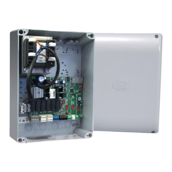
Dimensioni (mm) Descrizione delle parti Fusibile di linea 10. Connettore per scheda AF Morsettiera alimentazione di rete 11. Morsettiera antenna Morsettiere trasformatore 12. Morsettiera per dispositivi di sicurezza Trasformatore 13. Connettore per scheda R800 Morsettiera per modulo Green Power (GP1) 14. -
Page 4: Verifiche Preliminari
INDICAZIONI GENERALI PER L'INSTALLAZIONE L’installazione deve essere effettuata da personale qualificato ed esperto e nel pieno rispetto delle normative vigenti. ⚠ Attenzione! Prima di intervenire sul quadro comando, togliere la tensione di linea e, se presenti, scollegare le batterie. ⚠ Verifiche preliminari Prima di procedere all’installazione dell’automazione è... -
Page 5: Installazione
INSTALLAZIONE Fissaggio del quadro comando Fissare la base del quadro in una zona protetta; si consiglia di usare viti di diametro max. 6 mm testa bombata con impronta a croce . Forare sui fori presfondati . I fori presfondati hanno diametri differenti: 23, 29 e 37 mm. Attenzione a non danneggiare la scheda elettronica all’interno del quadro. -
Page 6: Dispositivi Di Comando
Collegamento motoriduttore con encoder Applicare all'interno del quadro comando una ferrite (non fornita, tipo FAIR-RITE materiale 31 mod. 2631102002) sui cavi dei M1 N1 ENC1 M2 N2 ENC2 motoriduttori. Motoriduttore con encoder (M2) 24 V DC, ritardato in chiusura. Motoriduttore con encoder (M1) 24 V DC, ritardato in apertura. -
Page 7: Dispositivi Di Sicurezza
Dispositivi di sicurezza 10 TS 2 C1 CX Collegamento fotocellule in Stop parziale o attesa ostacolo (contatto NC), vedi programmazione delle funzioni. Collegamento fotocellule in modalità riapertura durante la chiusura (contatto NC) vedi programmazione delle funzioni. Fotocellule Configurare il contatto C1 o CX (NC), ingresso per dispositivi di sicurezza tipo fotocellule, 10 TS 2 C1 CX conformi alle normative EN 12978. - Page 8 STOP TOTALE da pulsante (contatto 1-2) Di default, la funzione è abilitata. Per disabilitarla: selezionare i DIP come indicato e premere il tasto PROG sulla scheda. Il LED lampeggia e il buzzer suona 2 volte. Per ritornare all'impostazione di default, premere di nuovo PROG. Il LED rimane acceso e il buzzer suona per 1 s. Auto-apprendimento della corsa (vedi paragrafo Auto-apprendimento) Selezionare i DIP come indicato e premere il tasto PROG sulla scheda.
- Page 9 Chiusura automatica dopo apertura parziale o pedonale Di default, la funzione è disabilitata. Per abilitarla: Selezionare i DIP come indicato e premere il tasto PROG sulla scheda. Il LED PRG rimane acceso e il buzzer suona per 1 s. Per ritornare all'impostazione di default, premere di nuovo PROG. Il LED lampeggia e il buzzer suona 2 volte. ⚠ ...
- Page 10 Cancellazione di tutti gli utenti Selezionare i DIP come indicato e premere il tasto PROG sulla scheda per 5 s. A cancellazione avvenuta, il LED PRG rimane acceso e il buzzer suona per 1 s. Reset parametri Selezionare i DIP come indicato e premere il tasto PROG sulla scheda per 5 s. A cancellazione avvenuta, il LED PRG rimane acceso e il buzzer suona per 1 s.
-
Page 11: Led Di Segnalazione
Regolazioni delle funzioni Trimmer Descrizione delle funzioni Tempo chiusura automatica Regola il tempo di attesa del cancello in posizione di apertura. Trascorso questo tempo, viene effettuata A.C.T. automaticamente una manovra di chiusura. Il tempo di attesa può essere regolato da 1 a 180 secondi. Punto di accostamento (encoder abilitato) o tempo lavoro (encoder disabilitato) Regola il punto di inizio dell’accostamento dei motori prima del fi... -
Page 12: Risoluzione Dei Problemi
DICHIARAZIONE DI CONFORMITÀ Dichiarazione - Came Cancelli Automatici S.p.A. dichiara che questo prodotto è conforme ai requisiti essenziali e alle altre disposizioni pertinenti stabilite dalla direttiva 2006/95/CE e 2004/108/CE. Su richiesta è disponibile la copia conforme all’originale della dichiarazione di conformità. - Page 13 CONTROL PANEL 3 19 W 7 6E N FOR 24 V GEARMOTORS Installation manual ZL60 English...
-
Page 14: Reference Standards
Intended use The ZL60 control panel is designed to control CAME gearmotors for swing gates in residential and apartment block settings. Any installation and/or use other than that specified in this manual is forbidden. -
Page 15: Dimensions (Mm)
Dimensions (mm) Description of parts Line fuse 10. AF card connector Power supply terminal 11. Antenna terminals Transformer terminal 12. Safety devices terminal Transformer 13. R800 card connector Terminal for Green Power (GP1) module 14. Command and control devices terminals Trimmer 15. -
Page 16: Preliminary Checks
GENERAL INSTRUCTIONS FOR INSTALLING Only skilled, qualified staff must install this product. ⚠ Warning! Before working on the control panel, cut off the main current supply and, if present, remove any batteries. ⚠ Preliminary checks Before beginning the installation, do the following: ⚠... -
Page 17: Installation
INSTALLATION Fastening the control panel Fasten the control panel in a protected area; use rounded cross head screws with maximum 6 mm diameter. . Perforate the holes . The holes have different diameters: 23, 29 and 37 mm. ⚠ Be careful not to damage the control board inside the casing. Enter the cable gland with the corrugated tubes for threading the electrical cables . -
Page 18: Warning Device
Connecting gearmotor with encoder Apply a ferrite to the gearmotor cables inside of the control panel. It should be a FAIR-RITE type material 31 mod. 2631102002, M1 N1 ENC1 M2 N2 ENC2 and is not supplied. (M2) 24 V DC gearmotor with encoder, delayed in closing. -
Page 19: Safety Devices
Safety devices 10 TS 2 C1 CX Connecting photocells in partial stop or obstruction wait (contact NC), see features programming. Connecting photocells in reopen during closing mode (contact NC). See features programming. Photocells Configure contact C1 or CX (NC), input for safety devices such as photocells, which are 10 TS 2 C1 CX compliant with EN 12978 standards. - Page 20 TOTAL STOP from button (contact 1-2) By default, the feature is enabled. To disable it: select the DIPs as shown and press the PROG key on the board. The LED flashes and the buzzer sounds off twice. To return to the default setting, press PROG again. The LED stays on and the buzzer sounds off for 1 s. Self-learning of the gate travel (see Self-learning paragraph) Select the DIPs as shown and press the PROG key on the board.
- Page 21 Automatic closing after either partial or pedestrian opening By default, the feature is disabled. To enable it: Select the DIPs as shown and press the PROG key on the board. The PRG LED stays on and the buzzer sounds off for 1 s.
- Page 22 Deleting all users Select the DIPs as shown and press the PROG key on the board for 5 s. Once deleting is finished, the PRG LED stays on the buzzer sounds off for 1 s. Resetting parameters Select the DIPs as shown and press the PROG key on the board for 5 s. Once deleting is finished, the PRG LED stays on the buzzer sounds off for 1 s.
- Page 23 Adjusting the features Trimmer Description of features Automatic closing time A.C.T. It adjusts the gate wait time when open. Once this time has elapsed, an automatic closing takes place. The wait time can be adjusted to between 1 and 180 seconds. The final resting point (encoder enabled) or working time (encoder disabled) It adjusts the motors fi...
-
Page 24: Troubleshooting
DO NOT DISPOSE OF IN NATURE! DECLARATION OF CONFORMITY Declaration - Came Cancelli Automatici S.p.A. declares that this product conforms to the essential, pertinent requirements provided by directives 2006/95/CE and 2004/108/CE. An original copy of the declaration of conformity is available on request. -
Page 25: Manuel D'installation
ARMOIRE DE COMMANDE 319W76FR POUR MOTORÉDUCTEURS 24 V Manuel d’installation ZL60 Français... -
Page 26: Références Normatives
☞ RÉFÉRENCES NORMATIVES Came S.p.A. est une société certifiée pour les systèmes de gestion de la qualité ISO 9001 et de gestion environnementale ISO 14001. Le produit en question est conforme aux normes en vigueur citées dans la déclaration de conformité. -
Page 27: Description Des Parties
Dimensions (mm) Description des parties Fusible de ligne 10. Connecteur pour carte AF Barrette alimentation secteur 11. Barrette antenne Barrettes de connexion transformateur 12. Barrette pour dispositifs de sécurité Transformateur 13. Connecteur pour carte R800 Barrette de connexion pour module Green Power (GP1) 14. -
Page 28: Contrôles Préliminaires
INSTRUCTIONS GÉNÉRALES POUR L'INSTALLATION L’installation doit être effectuée par du personnel qualifié et dans le plein respect des normes en vigueur. ⚠ Attention ! Avant d'intervenir sur l'armoire de commande, mettre hors tension et déconnecter les éventuelles batteries. ⚠ Contrôles préliminaires Avant d'installer l'automatisme, il faut : ⚠... - Page 29 INSTALLATION Fixation de l'armoire de commande Fixer la base de l'armoire dans une zone protégée ; il est conseillé d'utiliser des vis d'un diamètre max. de 6 mm avec tête bombée cruciforme . Percer les trous préforés . Les trous préforés présentent des diamètres différents : 23, 29 et 37 mm. Avoir soin de ne pas endommager la carte électronique à...
-
Page 30: Dispositifs De Commande
Connexion du motoréducteur avec encodeur Appliquer, à l'intérieur de l'armoire de commande, une ferrite (non fournie, type FAIR-RITE matériau 31 mod. 2631102002) M1 N1 ENC1 M2 N2 ENC2 sur les câbles des motoréducteurs. Motoréducteur avec encodeur (M2) 24 V DC, retardé... -
Page 31: Dispositifs De Sécurité
Dispositifs de sécurité 10 TS 2 C1 CX Connexion des photocellules en mode Arrêt partiel ou Attente d'obstacle (contact NF), voir programmation des fonctions. Connexion des photocellules en modalité réouverture durant la fermeture (contact NF), voir programmation des fonctions. Photocellules Configurer le contact C1 ou CX (NF), entrée pour dispositifs de sécurité... - Page 32 ARRÊT TOTAL par bouton (contact 1-2) La fonction est, par défaut, activée. Pour la désactiver : sélectionner les commutateurs DIP comme indiqué et appuyer sur la touche PROG sur la carte. Le voyant clignote et le buzzer sonne 2 fois. Pour revenir à...
- Page 33 Fermeture automatique après une ouverture partielle ou piétonne La fonction est, par défaut, désactivée. Son activation requiert l'exécution des opérations suivantes : sélectionner les commutateurs DIP comme indiqué et enfoncer la touche PROG sur la carte. La LED PRG reste allumée et le buzzer sonne 1 s.
- Page 34 Suppression de tous les utilisateurs Sélectionner les commutateurs DIP comme indiqué et enfoncer la touche PROG sur la carte pendant 5 s. Après élimination, la LED PRG reste allumée et le buzzer sonne pendant 1 s. RàZ paramètres Sélectionner les commutateurs DIP comme indiqué et enfoncer la touche PROG sur la carte pendant 5 s. Après élimination, la LED PRG reste allumée et le buzzer sonne pendant 1 s.
-
Page 35: Réglages Des Fonctions
Réglages des fonctions Trimmers Description des fonctions Temps de fermeture automatique Permet de régler le délai d'attente du portail en position d'ouverture. Après écoulement de ce délai, une manœuvre de fermeture est automatiquement effectuée. Le temps d'attente peut être réglé entre 1 et 180 secondes. Point de rapprochement (encodeur activé) ou temps de fonctionnement (encodeur désactivé) Permet de régler le point de départ du rapprochement des moteurs avant la butée de fi... -
Page 36: Résolution Des Problèmes
DÉCLARATION DE CONFORMITÉ Déclaration - Came Cancelli Automatici S.p.A. déclare que ce produit est conforme aux exigences essentielles et aux dispositions pertinentes établies par les directives 2006/95/CE et 2004/108/CE. La copie conforme à l'original de la déclaration de conformité est disponible sur demande. - Page 37 БЛОК УПРАВЛЕНИЯ 319W76RU ЭЛЕКТРОПРИВОДАМИ 24 В Инструкция по монтажу ZL60 Русский...
-
Page 38: Условные Обозначения
питания LB39 для обеспечения бесперебойной работы в случае кратковременного отключения электропитания и зарядки аккумуляторов. Назначение Блок управления ZL60 разработан для управления приводами САМЕ 001OPP001 или 001OPB001 для распашных ворот в частных жилых домах и кондоминиумах. Запрещается использовать устройство не по назначению и устанавливать его методами, отличными от... -
Page 39: Основные Компоненты
Габаритные и установочные размеры (мм) Основные компоненты Входной предохранитель 10. Разъем для платы радиоприемника AF Контакты подключения сетевого электропитания 11. Контакты подключения антенны Контакты подключения трансформатора 12. Контакты подключения устройств безопасности Трансформатор 13. Разъем для платы R800 Контакты подключения модуля Green Рower (GP1) 14. -
Page 40: Предварительные Проверки
ОБЩИЕ ИНСТРУКЦИИ ПО МОНТАЖУ Монтаж должен производиться квалифицированным персоналом в полном соответствии с требованиями ⚠ действующих норм безопасности. Внимание! Перед началом работ по эксплуатации, ремонту, настройке и регулировке блока управления ⚠ отключите сетевое электропитание и/или отсоедините аккумуляторы. Предварительные проверки Перед началом монтажных работ выполните следующее: ⚠... - Page 41 МОНТАЖ Установка блока управления Установите основание блока управления в защищенном от повреждений месте. Рекомендуется использовать винты с выпуклой головкой под крест. Просверлите предварительно размеченные отверстия . Отверстия имеют различный диаметр: 23, 29 и 37 мм. Будьте предельно осторожны, чтобы не повредить плату блока управления! ⚠ ...
- Page 42 Подключение приводов с энкодером В блоке управления на провода приводов установите феррит (не входит в комплект поставки, тип FAIR-RITE, M1 N1 ENC1 M2 N2 ENC2 материал 31 мод. 2631102002). Привод с энкодером (M2) =24 В, с задержкой при закрывании Привод с энкодером (M1) =24 В, с задержкой...
-
Page 43: Устройства Безопасности
Устройства безопасности 10 TS 2 C1 CX Подключение фотоэлементов для выполнения функции "Частичный стоп" или "Обнаружение препятствия" (Н.З. контакты), см. раздел "Программирование функций" Подключение фотоэлементов для выполнения функции "Открывание в режиме закрывания" (Н.З. контакты), см. раздел "Программирования функций" Фотоэлементы безопасности Выполните... - Page 44 "СТОП" с помощью кнопки (контакты 1-2) По умолчанию функция включена. Чтобы ее отключить: установите DIP-переключатели, как показано на рисунке, и нажмите кнопку PROG на плате управления. Светодиодный индикатор начнет мигать, и зуммер издаст 2 звуковых сигнала. Чтобы вернуться к исходным настройкам, снова нажмите кнопку PROG. Светодиодный индикатор загорится ровным светом, и зуммер...
- Page 45 Автоматическое закрывание после частичного открывания или открывания для прохода пешеходов По умолчанию функция отключена. Для ее активации: установите DIP-переключатели, как показано на рисунке, и нажмите кнопку PROG на плате управления. Красный светодиодный индикатор загорится ровным светом, и зуммер издаст звуковой сигнал длительностью 1 с. Чтобы...
- Page 46 Удаление всех пользователей из памяти Установите DIP-переключатели, как показано на рисунке, нажмите кнопку PROG на плате управления и удерживайте ее в течение 5 с. По завершении удаления данных светодиодный индикатор PRG загорится ровным светом, а зуммер издаст звуковой сигнал длительностью 1 с. Сброс...
- Page 47 Регулировка функций с помощью триммеров Регулировка Описание функций Время автоматического закрывания Регулирует время ожидания в открытом положении ворот. По истечении заданного времени ворота A.C.T. автоматически закрываются. Время ожидания может составлять от 2 до 180 секунд. Точка начала замедления (при включенном энкодере) или время работы привода (при отключенном энкодере) Регулирует...
-
Page 48: Заключительные Работы
НЕ ЗАГРЯЗНЯЙТЕ ОКРУЖАЮЩУЮ СРЕДУ! ДЕКЛАРАЦИЯ О СООТВЕТСТВИИ Декларация - Came Cancelli Automatici S.p.A. заявляет, что настоящее изделие соответствует основным требованиям и положениям, установленным Директивами 2006/95/CE и 2004/108/CE. По требованию заказчика может быть предоставлена копия декларации, соответствующая оригиналу. IT • Per ogni ulteriore informazione su azienda, prodotti e assistenza nella vostra lingua: EN •...
Need help?
Do you have a question about the ZL60 and is the answer not in the manual?
Questions and answers