Table of Contents
Advertisement
Advertisement
Table of Contents

Related Manuals for CAME ZL19N


Summary of Contents for CAME ZL19N
- Page 1 CONTROL PANEL 319U33EN FOR 24V GEARMOTORS INSTALLATION MANUAL ZL19N...
-
Page 2: Intended Use
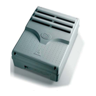
This symbol tells you what to tell the end-user. 2.1 Intended use The ZL19N control panel is engineered and built by Came Cancelli Automatici S.p.A. to command swing gate operators of the FERNI and FROG 24 V DC series. Any installation and use other than that specified in this manual is forbidden. - Page 3 You can also connect: - gate open warning-lamp; - the cycle lamp; - the electro lock; - the 002LB18 for emergency operations in case of power outages. Types of defi nable commands: - opening/closing; -opening/closing with maintained action; - partial opening; - partial stop;...
- Page 4 4.2 Main components Transformers Speed adjuster connectors Terminal board for connecting the 002LB18 card (if unused, make sure that bridges are connected among A-B;C-D; E-F; G-h) Accessories fuse Card fuse Amperometric sensitivity during travel adjustment trimmer Amperometric sensitity during travel adjustment trimmer Amperometric sensitivity during slowdown adjustment trimmer...
- Page 5 5.2 Tools and equipment Make sure you have all the tools and materials needed to carry out the installation in total safety and in accordance with current regulations. Here are some examples. 5.3 Anchoring and installing the box 1) Secure the base of the panel in a safe area; yes max. 6 mm Head with to.
- Page 6 6 Electrical connections 2 FROG 24 V motors M1 N1 M2 N2 Power supply Opening brown slowdown blue Closing brown slowdown 1 FROG 24 V motor M1 N1 M2 N2 RA2-C= Opening slowdown Power supply RC2-C= Closing slowdown 2 FERNI 24 V motors Shortcircuit M1 N1 M2 N2 Power supply...
- Page 7 Accessories power source Terminals for powering accessories: - at 24 V (AC) with 230 V (AC) - at 24 V (DC) with 24 V (DC) Overall allowed power: 40 W 230 V AC powered, 50 / 60 Hz frequency Electro lock connection (12V-15 W max.) Lighting and warning devices Flashing-light (contact rated for: 24 V - 25 W max.
- Page 8 Safety devices Delta-S (N.C.) "partial stop" contact Input for safety devices like photocells, sensitive edges and other devices that comply with EN 12978 regulations. Stops gate leaves if they are moving and then automatically closes them. If unused set DIP switch n.8 to ON. C1=Reopening when closing (N.C.) Contact»...
- Page 9 Command devices Stop button ((N.C.) contact.) Gate stop button with exclusion of automatic closing, to resume movement press command button or transmitter button. If unused set DIP switch n.9 to ON. Key-switch selector and/or opening button N.O. contact) - Command for gate opening. Key switch selector and/or opening button (N.O.
- Page 10 ACCESSORIES FUSE 2A 7 Selecting functions L1T L2T CONTROL BOARD ELECTRIC LOCK FUSE 2A FUSE 315mA MOTOR 1 MOTOR 2 FUSE 10A FUSE 10A CONTROL BOARD 10-WAY DIP-SWITCH ZL19 FINE ADJ. SLOWDOWN ZL19A AMP.SENS. AMP.SENS. AMP. SENS. Z Z L L 1 1 9 9 B B C C H H 1 1 C C H H 2 2 B B 1 1 / / B B 2 2...
- Page 11 8 Settings - END ADJ/SENS. * End adjustement of amperometric sensor during travel:min/max. - AMP SENS. * Adusts the amperometric sensitivity which controls the force developed by the motor during movement; if the force exceeds the adjusted level, the system intervenes and inverts the direction of travel.
- Page 12 Adjusting travel and slowdown speeds For adjusting the travel and slowdown speeds, move the fastons M1 slowdown faston M2 slowdown faston M1 travel faston M2 travel faston 9 Activating the radio command Antenna POS. A POS. B Connect the antenna cable to the terminals.
- Page 13 CUT THE MAIN POWER SUPPLY (and/or disconnect the batteries) and snap in the radio-frequency card into the electronic card. N.B.: The electronic card recognises the radio-frequency card only when it is powered up. AF card Transmitters ATOMO AT01 • AT02 AT04 See instructions sheet in the packa- ge of the AF43SR radiofrequency card...
- Page 14 Memorisation CH1 = Channel for direct function command to gearmotor control panel ("open only" command / "open-close-invert" command o "open-stop-close-stop", depending on selection made on DIP switches 2 and 3). CH2 = Channel for direct commands to an accessory device connected on B1-B2. 1) Keep CH1 button pressed on the electronic card.
- Page 15 Management System in compliance with the UNI EN ISO 14001 standard to ensure environmental protection. Please help us to safeguard the environment. At CAME we believe this to be one of the fundamentals in its market operations and development strategies. Just follow these short disposal instructions: DISPOSING OF THE PACKAGING The components of the packaging (i.e.
- Page 16 (+34) 91 52 85 009 127273, Moscow Moscow (+34) 91 46 85 442 (+7) 495 739 00 69 (+7) 495 739 00 69 (ext. 226) CAME United Kingdom Ltd. CAME United Kingdom Ltd. GREAT BRITAIN PORTUGAL CAME Portugal CAME Portugal...
Need help?
Do you have a question about the ZL19N and is the answer not in the manual?
Questions and answers