CAME ZLX24SA Installation Manual
Hide thumbs
Also See for ZLX24SA:
- Installation manual (41 pages) ,
- Installation manual (48 pages) ,
- Installation manual (60 pages)

Related Manuals for CAME ZLX24SA


Summary of Contents for CAME ZLX24SA
- Page 1 Control panel for 24 V gearmotors FA01876-EN ZLX24SA ZLX24SR INSTALLATION MANUAL English...
- Page 2 fi nal installation to comply with the Machinery Directive (2006/42/EC) and with the reference harmonised technical standards are specifi ed in the general CAME product catalogue or on the website www.came.com. • Check that the temperature ranges given are suitable for the installation site.
- Page 3 • Before installation, check that the guided part is in good mechanical condition, and that it opens and closes correctly. • The product cannot be used to automate any guided part that includes a pedestrian gate, unless it can only be enabled when the pedestrian gate is secured.
- Page 4 UNI EN ISO 14001 standard to ensure that the environment is respected and safeguarded. Please continue safeguarding the environment. At CAME we consider it one of the fundamentals of our operating and market strategies. Simply follow these brief disposal guidelines: DISPOSING OF THE PACKAGING The packaging materials (cardboard, plastic, etc.) can be disposed of easily as solid urban waste, separated for recycling.
- Page 5 Description 801QA-0060 ZLX24SA - Multifunction control panel, with 230 VAC power supply, for 24 V swing gates with two leaves, with graphic programming display and signalling, safety device self-diagnostics, adaptive speed and torque technology, BUS CXN, 4 safety inputs and memory space for up to 1000 users.
-
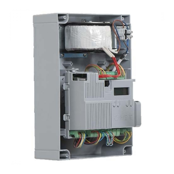
Page 6: Description Of Parts
Terminal boards for connecting micro limit switches and/ Terminal board for B1-B2 output or encoders Memory Roll card connector Terminal board for connecting the gearmotor with Connector for CAME KEY encoder or with slowdown switch and electric lock Display Accessories fuse Programming buttons... - Page 7 Optional accessories RGSM001 module (806SA-0010) RLB battery charger board (002RLB) SMA module (009SMA) To control all required motors from the control panel, use two 7Ah batteries (846XG-0030) installed on an external panel.
- Page 8 Size...
- Page 9 For information on connecting products not covered in this manual, please see the documentation accompanying the products themselves. To connect the encoder, use a FRORPU 3 x 0.5 mm² cable or a cable supplied by CAME on request (item code 801XA-0020).
-
Page 10: Installation
INSTALLATION Preparing the control panel... - Page 11 Fastening the control panel DIN rail Standard...
-
Page 12: Electrical Connections
ELECTRICAL CONNECTIONS Preparing the electrical cables Connect all wires and cables in compliance with the law. Use cable glands to connect the devices to the control panel. One of these must be used exclusively for the power supply cable. -
Page 13: Power Supply
Power supply Connecting to the mains (230/120 V AC - 50/60 Hz) F - Line fuse L - Phase N - Neutral Earth The strap used to fi x the cables is not supplied. For subsequent connections, reposition the control board and remove the board protection. - Page 14 The outputs deliver 24 V DC when the batteries start operating, if they are installed. Device Output Power supply (V) Power (W) Auxiliary contact B1 - B2 24 (24V AC/DC) BUS CXN 15 DC Do not connect anything other than CAME BUS accessories.
- Page 15 Gearmotors M1 =Gearmotor delayed while opening M2 =Gearmotor delayed while closing Where there is only one gearmotor in the system, make the electrical connections on the gearmotor (M2). Gearmotor with encoder E1 - E2 - M1 N1 ENC1 EB1+VB M2 N2 ENC2 EB2+VB FC2 FA2 F FC1 FA1 F FROG-A24E / FERNI / FERNI-V / F4024E / F4024EP...
- Page 16 M1 N1 ENC1 EB1+VB M2 N2 ENC2 EB2+VB ATS / AXO / FTX / FAST-70 / AMICO / AXI M2 N2 ENC2 EB2+VB M1 N1 ENC1 EB1+VB STYLO-RME M1 N1 ENC1 EB1+VB M2 N2 ENC2 EB2+VB STYLO-ME...
- Page 17 Gearmotors with slowdown switches FC1 FA1 F FC2 FA2 F M1 N1 ENC1 EB1+VB M2 N2 ENC2 EB2+VB A3024N / A5024N E1 - E2 - M1 N1 ENC1 EB1+VB M2 N2 ENC2 EB2+VB FC1 FA1 F FC2 FA2 F FROG-A24 E1 - E2 - M1 N1 ENC1 EB1+VB...
- Page 18 Gearmotors without encoder M2 N2 ENC2 EB2+VB M1 N1 ENC1 EB1+VB...
- Page 19 Devices with BUS CXN system The CXN CAME system is a two-wire non-polarised communication BUS which allows you to connect up all compatible CAME devices. Connection to the BUS can be in a chain, star or mixed formation. Once the system has been wired, and after having set the address on each device, the function of each accessory can be confi...
- Page 20 Maximum number of devices that can be connected, by type Type of device Maximum number of devices per type Selectors Photocell pairs Interfaces Flashing beacons BUS CXN device consumption Scan the QR code to access an interactive table showing consumption data, and calculate the maximum number of BUS devices you can connect to the control panel.
- Page 21 Command and control devices STOP button (NC contact) This stops the operator and excludes automatic closing. Use a control device to resume movement. When the contact is being used, it must be activated during programming. See function [Total stop]. Control device (NO contact) Open command When the [Hold-to-run] function is active, a control device must be set to OPEN.
-
Page 22: Signalling Devices
Signalling devices Flashing beacon It fl ashes when the operator opens and closes. Additional light It increases the light in the manoeuvring area. See [Additional light] function. Operator status warning light It notifi es the user of the operator status. See function [Passage-open warning light]. -
Page 23: Safety Devices
Safety devices During programming, confi gure the type of action that must be performed by the device connected to the input. Connect the safety devices to the CX and/or CY and/or CZ and/or CK inputs. If used, the contacts C1 CX CY CZ CK must be confi gured during programming. For systems with multiple pairs of photocells, please see the manual for the relevant accessory. - Page 24 DXR - DLX photocells DXR - DLX photocells Standard connection Connection with safety test See [Safety devices test] function. 10 TS 2 CX CY CZ CK 10 11 E E3 5 10 TS 2 CX CY CZ CK 10 11 E E3 5 10 11 OUT 10 11 OUT 10 11 SY...
-
Page 25: Getting Started
PROGRAMMING Programming button functions ESC button The ESC button is used to perform the operations described below. Exit the menu Delete the changes Go back to the previous screen Stop the operator < > buttons The <> buttons are used to perform the operations described below. Navigate the menu Increase or decrease values ENTER button... - Page 26 Diagrams showing leaf speed, slowdown and approach points Closing limit-switch Opening speed Opening limit-switch Closing speed Opening slowdown point Opening slowdown speed Closing slowdown point Closing slowdown speed Opening approach point Approach speed (fi xed) Closing approach point Invert-motion zone in case of obstructions Stop-motion zone in case of obstructions Graph showing speed curves during movement, slowdown and approach.
-
Page 27: Functions Menu
Without using slowdown space (slowdown space = 0) Opening or closing speed Approach speed (fi xed) Obstruction travel sensitivity Opening or closing limit-switch Opening or closing approach point Virtual encoder For gearmotors without an encoder or with the encoder deactivated, travel is managed using a VIRTUAL ENCODER. ALWAYS calibrate the travel, as with motors with an encoder. - Page 28 Level 1 Level 2 Level 3 Level 4 Confi guration Motor settings Number of motors Motor type Encoder Reduce speed Limit-switch function Input type FC/FA Motor test Travel calibration Motor power Confi gure M1 Motor type Encoder Limit-switch function Input type FC/FA Reduce speed Motor power Confi...
- Page 29 Gate travel settings Opening speed Closing speed Travel AST control Adjusting the partial opening Op. approach point Cl. approach point Opening slowdown point Closing slowdown point Opening slowdown speed Closing slowdown speed Slowdown AST control Impact test Confi gure M1 Opening speed Closing speed Op.
- Page 30 Wired safety devices Total stop CX input CY input CZ input CK input Safety devices test RIO safety devices RIO ED T1 RIO ED T2 RIO PH T1 RIO PH T2 BUS Devices BUS Photocell 1 Photocell BUS 2 Photocell BUS 3 Photocell BUS 4 Photocell BUS 5 Photocell BUS 6...
- Page 31 BUS 6 key selector Key to the right Key to the left BUS 7 key selector Key to the right Key to the left I/O module 1 input I1 input I2 Relay output Light output I/O module 2 input I1 input I2 Relay output Light output...
- Page 32 Times Automatic close Automatic partial close M1 open delay M2 close delay Manage lights Passage-open warning light Light E3 Courtesy time Pre-fl ashing time RSE communication CRP address RSE speed External memory Save data Read data Parameter reset Guided procedure (Wizard) Manage users New user Remove user...
- Page 33 Timer management Show clock Set the clock Automatic DST Time format Create new timer Open Start time End time Days of the week Partial opening Start time End time Days of the week B1-B2 output Start time End time Days of the week BUS 1 module relay Start time End time...
- Page 34 Functions menu Number of motors Set the number of motors that control the gate. Confi guration> Number of motors M1+M2 (Default) Motor settings Motor type Set the type of gearmotor installed on M1 and M2. If the value set for M1 is diff erent to the value set for M2, only the value for M2 is shown here. Confi...
- Page 35 Limit-switch function Set the operation of the inputs for slowdown/end-of-travel switches. The function only appears for motors confi gured for this purpose. If the value set for M1 is diff erent to the value set for M2, only the value for M2 is shown here. After modifying the function of the slowdown/end-of-travel inputs, recalibrate [Function Travel calibration].
- Page 36 Motor power Setting power range of motors connected on M1 and M2. The parameter is used only with generic motors. [Motor type] function set to [Generic]. Confi guration> Motor power Minimum power [up to 120W] Motor settings Medium power (Default) [up to 200W] Maximum power [more than 200W] Confi...
- Page 37 Travel AST control Adjust the obstruction detection sensitivity during the gate travel in percentage terms. Confi guration> Travel AST control Deactivated (Default) Gate travel settings Maximum thrust and low obstruction sensitivity. Minimum Average Maximum (*) Minimum thrust and high obstruction sensitivity. Customised Customised closing Customised opening...
- Page 38 Opening slowdown point Set the percentage of the total travel to be used for the M1 and M2 opening slowdown. If the value set for M1 is diff erent to the value set for M2, only the value for M2 is shown here. Confi...
- Page 39 Slowdown AST control Adjust the obstruction detection sensitivity during slowdown in percentage terms. The parameter is only used if the opening or closing slowdown point is active. Confi guration> Slowdown AST control Deactivated (Default) Gate travel settings Maximum thrust and low obstruction sensitivity. Minimum Average Maximum...
- Page 40 Confi gure travel M2 Modify certain parameters previously described for motor M2 only (where diff erent from M1). The function only appears with M1+M2 selected under [Number of motors]. Confi guration> Opening speed See the specifi c parameters for each function. Gate travel settings>...
- Page 41 Safety devices test Check that the photocells connected to the selected inputs are operating correctly, after each opening and closing command. Run the test by connecting the photocells to the TS terminal [see paragraph on Safety devices]. Confi guration> Safety devices test Deactivated (Default) Wired safety devices CX _ _ _...
- Page 42 Photocell BUS <n> Associate a function with the photocell BUS <n> input. <n> is between 1 and 8 and corresponds to the address set on the photocell dip-switch The function only appears if there is a BUS photocell connected. Confi guration> BUS Photocell 1 Deactivated (Default) BUS Devices...
- Page 43 I/O module <n> - Inputs Associate a function to the I/O module <n> inputs. <n> is between 1 and 2 and corresponds to the address set on the module dip switch. The function only appears if there is a BUS I/O module connected. Confi...
- Page 44 <Opening colour> BUS fl ashing beacon Set the BUS fl ashing beacon colour during operator opening. The function only appears if there is a BUS fl ashing beacon connected. Confi guration> Opening colour White BUS Devices> Yellow BUS fl ashing beacon Orange Red (Default) Purple...
- Page 45 <Pre-fl ashing colour> BUS fl ashing beacon On the BUS fl ashing beacon, set the fl ash colour for before opening and closing manoeuvres (pre-fl ash). The function only appears if there is a BUS fl ashing beacon connected. Confi guration> Pre-fl...
- Page 46 Command 2-7 Associate a command to the connected device on 2-7. Confi guration> Command 2-7 Step-by-step (Default) - The fi rst command is to open and Command inputs the second to close. Sequential - The fi rst command is to open, the second to STOP, the third to close and the fourth to STOP.
- Page 47 Hold-to-run With the function active, the operator stops moving (opening or closing) when the control device is released. When the function is active, it excludes all other control devices. Confi guration> Hold-to-run Deactivated (Default) Functions Obstacle with motor stopped With the function active, the operator remains stopped if the safety devices detect an obstacle. The function is active when the gate is closed, open or after a complete stop.
- Page 48 M2 closing delay time Adjust the delayed opening of the second leaf compared to the fi rst. Confi guration> M2 close delay Times 1 to 25 seconds (Default 2) Passage-open warning light It notifi es the user of the operator status. The device is connected to output/terminal 5.
- Page 49 RSE speed Set the communication speed of the remote connection system. Confi guration> RSE speed 4800 bps RSE communication 9600 bps 14400 bps 19200 bps 38400 bps (Default) 57600 bps 115200 bps Save data Save user data, timings and confi gurations to the memory device (memory roll). The function is displayed only when a memory roll card is inserted into the control board.
- Page 50 New user Register up to a maximum of 1000 users and assign a function to each one. The operation can be carried out by using a transmitter or a BUS selector device (e.g. a keypad or transponder reader). The board that manages the transmitters (AF) must be inserted into the connector. Manage users New user Choose the function to be assigned to the user.
- Page 51 Radio decoding Choose the type of radio coding for the transmitters enabled to control the operator. If you choose the type of radio coding for the transmitters [Rolling code] or [TW key block], any transmitters saved previously will be deleted. Manage users Radio decoding All decoding (Default)
- Page 52 FW version Display the fi rmware version and the GUI installed. Information FW version Use the < > arrows to show: FW MC.x.x.xx (motor board fi rmware version) FW UI.x.x.xx (display board fi rmware version) GUI x.x (graphics) BUS device status Show the status of all devices that can be connected to the BUS and managed by the fi...
- Page 53 Manoeuvre counter View the number of total or partial operator manoeuvres (after maintenance). The number of manoeuvres is the number shown multiplied by 100. Information Manoeuvre counter Total manoeuvres - Manoeuvres performed since the operator was installed. Partial manoeuvres - Manoeuvres carried out after the last maintenance.
- Page 54 Automatic DST Enable automatic daylight saving time setting. Valid in Central Europe only UTC+1. Timer management Automatic DST Deactivated (Default) Summer changeover: +1 hour on the last Sunday in March (change to daylight saving time). Winter changeover: -1 hour on the last Sunday in October (change to standard time).
- Page 55 Language Set the display language. Language Italiano (IT) English (EN) (Default) Français (FR) Deutsch (DE) Español (ES) Português (PT) Русский (RU) Polski (PL) Românesc (RO) Magyar (HU) Hrvatski (HR) Yкраїнський (UA) Nederlands (NL) Enable password Set a 4-digit password. The password will be requested to anyone who wants to access the main menu. This option only shows if a password has NOT been enabled.
-
Page 56: Import/Export Data
When you reset the control board, all saved users, set times, manoeuvre confi gurations and calibration operations are deleted. When using a CAME KEY device, always update the board fi rmware to the latest version. Import/export data Save user data and system confi guration data on a MEMORY ROLL card. - Page 57 DISPLAY WARNINGS KEY The encoder is deactivated. The [Impact test] function is on. The operator detected an obstacle during closing. The operator detected an obstacle during opening. The operator detected two obstacles during closing. The number on the display varies according to the number of obstructions detected. When the maximum number of detected obstructions has been reached, the operator stops and an error message shows on the display.
- Page 58 RIO safety device active The <n> value is associated with the selected parameter for the functions [RIO P<n> ED T1 - RIO ED T2] and [RIO PH T1 - RIO PH T2] ID confl ict detected on BUS devices. BUS address conflict No BUS device with a safety function confi...
-
Page 59: Error Messages
Error messages Motor M1 calibration error Motor M2 calibration error Encoder signal not detected error Service test failure error Operating time error Consecutive obstacles detected during closing Consecutive obstacles detected during opening Maximum number of obstacles Motor supply voltage missing or insuffi cient Limit switch input error or both limit switches open Incompatible transmitter error Wireless system communication error... -
Page 60: Final Operations
FINAL OPERATIONS Before closing up the casing, check that the cable inlets are sealed to stop insects getting in and to prevent damp. - Page 64 AFFIX THE PRODUCT LABEL FROM THE BOX HERE CAME S.p.A. Via Martiri della Libertà, 15 31030 Dosson di Casier Treviso – Italy Tel. (+39) 0422 4940 Fax (+39) 0422 4941 info@came.com - www.came.com...
Need help?
Do you have a question about the ZLX24SA and is the answer not in the manual?
Questions and answers
can you explain the easiest way in steps to configure the gate travel, to gain level closing and to gain stop prior to the gate stops, many thanks
For the CAME ZLX24SA, configure the closing approach point and closing slowdown point settings to achieve level closing and stop before the gate fully stops.
1. Closing Approach Point:
- Go to Configuration > Cl. approach point.
- Set the percentage of total travel for the closing approach (default is 8.0%).
- Adjust between 0.5% to 15.0% as needed.
2. Closing Slowdown Point:
- Go to Configuration > Closing slowdown point.
- Set the percentage of total travel for the closing slowdown (default is deactivated).
- Adjust between 1% to 50% to ensure a gradual stop before the gate fully closes.
Adjust these values based on the specific gate movement required.
This answer is automatically generated