Sign In
Upload
Manuals
Brands
Burkert Manuals
Controller
8750
User Manuals: Burkert 8750 Flow rate controller
Manuals and User Guides for Burkert 8750 Flow rate controller. We have
2
Burkert 8750 Flow rate controller manuals available for free PDF download: Short Instructions For Commissioning, Quick Start Manual
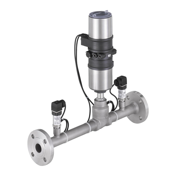
Burkert 8750 Short Instructions For Commissioning (82 pages)
Flow controller
Brand:
Burkert
| Category:
Controller
| Size: 2 MB
Table of Contents
English
3
Table of Contents
3
Note on These Short Operating Instructions
4
Symbols
5
Intended Use
5
Safety Notes
6
Transport, Storage
6
Disposal
6
Description
7
Sequence of Steps from Assembly up to Commissioning a System
8
Technical Data
9
Dimensions
10
Intake Sections to en ISO 5167-1
10
Action Diagram
10
Installation in a System
11
Connection of the Control Air
11
Electrical Connections
11
Electrical Interfaces
12
PIN Designation and PIN Allocation
12
Prefabricated Cables as Accessories
13
Kv-Value Table for Various FMR Versions
14
Process Operating Level and Configuration Level
15
Display and Key Functions
15
Key Functions in the Process Operating Level
15
Key Functions in the Configuration Level
15
Factory Settings and Necessary User Settings
15
Program Sequence for Commissioning (Menu Items and Explanations)
16
Program Function P.CO TUNE (PROCESSTUNE)
22
Prerequisites for Starting P.CO TUNE (PROCESSTUNE)
22
Preparation for Entry of a Setpoint Step for PROCESSTUNE
22
Explanations Concerning Starting Value
23
Possible Display of Process Values in the Automatic Mode
23
Entering the Setpoint Step and Initiating PROCESSTUNE
23
Evaluation of Control Results after Commissioning
24
Measures for Improving the Control Behaviour
24
Program Function P.CO LEAK (Leak Detection)
24
Maintenance
26
Errors, Malfunctions and Their Remedy
26
Deutsch
29
Hinweis zu dieser Kurzbedienungsanleitung
30
Bestimmungsgemäße Verwendung
31
Darstellungsmittel
31
Allgemeine Sicherheitshinweise
32
Entsorgung
32
Transport und Lagerung
32
Beschreibung
33
Schrittfolge von der Montage bis zur Inbetriebnahme einer Anlage
34
Technische Daten
35
Abmessungen
36
Einlaufstrecken nach en ISO 5167-1
36
Wirkungsschema
36
Anschluss der Steuerluft
37
Einbau in eine Anlage
37
Elektrische Anschlüsse
37
Elektrische Schnittstellen
38
PIN-Kennzeichnung und PIN-Belegung
38
Vorkonfektionierte Kabel als Zubehör
39
Kv-Wert-Tabelle für Verschieden FMR-Versionen
40
Display und Tastenfunktionen
41
Prozessbedienebene und Konfigurierebene
41
Tastenfunktionen in der Konfigurierebene
41
Tastenfunktionen in der Prozessbedienebene
41
Werkseinstellungen und Erforderliche Bedienereinstellungen
41
Programmablauf zur Inbetriebnahme (Menüpunkte und Erläuterungen)
42
Programmfunktion P.CO TUNE (PROZESSTUNE)
48
Voraussetzungen zum Start von P.CO TUNE (PROZESSTUNE)
48
Vorbereitung zur Eingabe eines Sollwertsprunges für PROZESSTUNE
48
Erläuterungen zum Startwert
49
Mögliche Anzeige von Prozesswerten IM Automatikbetrieb
49
Sollwertsprung Eingeben und PROZESSTUNE Auslösen
49
Bewertung der Regelergebnisse nach der Inbetriebnahme
50
Maßnahmen zur Verbesserung des Regelverhaltens
50
Programmfunktion P.CO LEAK (Leckageermittlung)
50
Fehler, Störungen und Abhilfe
52
Wartung
52
Français
55
Remarque Sur Cette Brève Notice de L'utilisateur
56
Symboles Utilisés
57
Utilisation Conforme À la Destination
57
Consignes Générales de Sécurité
58
Réglementation Concernant Le Déchets
58
Transport Et Stockage
58
Description
59
Etapes À Suivre du Montage Jusqu'à la Mise en Service D'une Installation Avec FMR
60
Caractéristiques Techniques
61
Dimensions
63
Schéma de Principe
63
Connexions Électriques
64
Montage Dans Une Installation
64
Raccordement du Fluide de Pilotage
64
Identification Et Affectation des Broches
65
Interfaces Électriques
65
Câbles Préconfectionné Comme Accessoires
66
Tableau des Valeurs Kv Pour Différentes Versions de FMR
67
Ecran Et Fonctions des Touches
68
Fonction des Touches en Mode Configuration
68
Fonctions des Touches en Mode Normal
68
Mode Normal Et Mode Configuration
68
Réglages en Usine Et Réglages Nécessaires de L'utilisateur
68
Programme de Mise en Service ( Fonctions Et Explications)
69
Conditions du Démarrage de P.CO TUNE (AUTO-ADAPTATIVE)
75
Fonction P.CO TUNE (AUTO-ADAPTATIVE)
75
Préparation À L'entrée D'un Saut de la Valeur de Consigne Pour AUTO-ADAPTATIVE
75
Affichages Possibles de Valeurs du Process en Mode Automatique
76
Entrée du Saut de la Valeur de Consigne Et Lancement de AUTO-ADAPTATIVE
76
Explications Sur la Valeur de Démarrage
76
Evaluation des Résultats de Réglage Après la Mise en Service
77
Fonction P.CO LEAK (Détection des Fuites)
77
Mesure D'amélioration du Mode de Régulation
77
Défauts, Dysfonctionnements Et Actions Correctives
79
Maintenance
79
Advertisement
Burkert 8750 Quick Start Manual (66 pages)
Flow controller
Brand:
Burkert
| Category:
Controller
| Size: 1 MB
Table of Contents
Table of Contents
3
1 Quickstart Guide
5
Definition of Terms / Abbreviation
5
2 Symbols
5
3 Authorized Use
6
Restrictions
6
4 Basic Safety Instructions
6
5 General Information
8
Contact Address
8
Warranty
8
Information on the Internet
8
6 System Description
8
General Description
8
Structure
9
7 Technical Data
11
Conformity
11
Standards
11
Operating Conditions
11
Mechanical Data
11
Type Label (Example)
12
Fluidic Data
12
Electrical Data
13
8 Control and Display Elements
15
Function of the Keys
15
Operating State
16
Operating Levels
17
Display in AUTOMATIC Operating State
17
Master Code
18
9 Assembly
19
Safety Instructions
19
Before Installation
19
Pneumatic Connection of the Process Controller
19
10 Electrical Installation
21
Electrical Installation, 24 V DC with Circular Plug-In Connector (Multi-Pole Variant)
22
Electrical Installation PROFIBUS DP
23
Electrical Installation Devicenet
25
11 Start-Up 24 V DC
26
General Procedure for Creating Settings for the Flow Controller
27
Define Basic Settings
27
Automatic Adjustment (X.TUNE)
28
Configuring the F.CONTROL Auxiliary Function
29
Leakage Air Characteristic for FMR (Leaktune)
32
12 Additional Fmr Functions
33
Activating and Deactivating Auxiliary Functions
35
CAL.USER - Changing the Factory Calibration
35
OUTPUT - Configuration of the Analog Output
37
13 Profibus Dp Start-Up
38
Settings in BUS.COMM
38
Configuration of the Process Values
39
14 Devicenet Start-Up
42
Settings in BUS.COMM
42
Configuration of the Process Data
44
15 Safety End Positions
48
16 Error Messages
49
Error Messages on Field Bus Devices
51
Other Error Messages
52
17 Accessories
53
18 Disassembly
53
19 Operating Structure
54
20 Transport, Storage, Packaging
63
Advertisement
Related Products
Burkert 8756 BATCH
Burkert 8793
Burkert 8711
Burkert 8716
Burkert MassFlowMeter 8700
Burkert 8702 Series
Burkert 8706
Burkert 8713
Burkert 8718
Burkert 8709
Burkert Categories
Control Unit
Controller
Measuring Instruments
Transmitter
Accessories
More Burkert Manuals
Login
Sign In
OR
Sign in with Facebook
Sign in with Google
Upload manual
Upload from disk
Upload from URL