Burkert 8756 BATCH Operating Instructions Manual
Hide thumbs
Also See for 8756 BATCH:
- Operating instructions manual (52 pages) ,
- Operating instructions manual (62 pages)

Related Manuals for Burkert 8756 BATCH


Summary of Contents for Burkert 8756 BATCH
- Page 1 Type 8756 BATCH büS / CANopen Mass Flow Controller for the dosing of liquids Operating Instructions...
- Page 2 We reserve the right to make technical changes without notice. © Bürkert SAS, 2021 - 2023 Operating Instructions 2301/02_EU-ML 00572214 / Original EN...
-
Page 3: Table Of Contents
Type 8756 BATCH Table of contents TABLE OF CONTENTS 1 About this document.......................... 6 Manufacturer ............................ 6 Used symbols ........................... 6 Terms and abbreviations ........................ 7 2 Safety instructions............................ 8 Intended use ............................. 8 Safety.............................. 8 3 Product description.......................... 10 Design............................. 10 Product identification ........................ 12 3.2.1... - Page 4 Type 8756 BATCH Table of contents 6.3.3 With CANopen cables...................... 25 Connect the functional earth ...................... 26 7 Commissioning ............................ 27 Safety instructions .......................... 27 Commissioning procedure (MFC with on/off valve) ............... 27 8 Setting and operation.......................... 29 Safety instructions .......................... 29 Dosing types........................... 30 8.2.1...
- Page 5 Type 8756 BATCH Table of contents 10.11 Unstable measured value ....................... 46 10.12 Outgassing or bubble formation at the product outlet .............. 47 10.13 Dosing quantity cannot be reached .................... 47 10.14 Quantity is not dosed precisely ...................... 48 10.15 Drippling ............................ 48 11 Spare parts and accessories ........................ 49...
-
Page 6: About This Document
Before starting any work on the product, read and observe the respective sections of the document. Keep the document available for reference and give it to the next user. Contact the Bürkert sales office for any questions. Further information concerning the product at country.burkert.com. Manufacturer Bürkert Fluid Control Systems Christian-Bürkert-Str. -
Page 7: Terms And Abbreviations
Type 8756 BATCH About this document Terms and abbreviations The terms and abbreviations are used in this document to refer to following definitions. Device / Product Type 8756 BATCH Mass Flow Controller büS Bürkert system bus, a communication bus developed by Bürkert and based on the... -
Page 8: Safety Instructions
Safety instructions SAFETY INSTRUCTIONS Intended use The MFC Type 8756 BATCH is designed to measure the mass flow rate of liquids and dose liquids. The permitted media are listed in Technical data [} 15] Only trained and qualified personnel may install, operate and maintain the device. See qualification of persons in Safety [} 8]... - Page 9 Type 8756 BATCH Safety instructions Electric shock due to electrical components Touching live parts can result in severe electric shock. This can lead to serious personal injury or death. Before working on the device or the system, switch off the power supply. Secure it against reactivation.
-
Page 10: Product Description
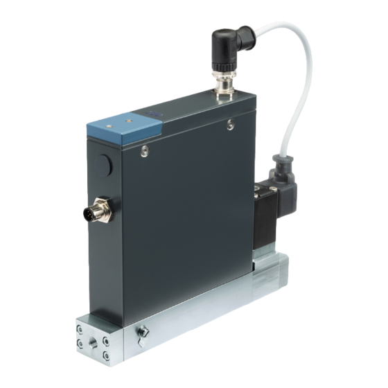
Type 8756 BATCH Product description PRODUCT DESCRIPTION The mass flow controller Type 8756 BATCH with integrated batch controller is especially suitable for dosing small quantities of liquids with the highest accuracy. This manual describes following product variant: MFC büS/CANopen with an on/off valve MFC büS/CANopen with an interface for a modular actuator... - Page 11 Type 8756 BATCH Product description MFC BATCH for modular actuator 7 8 9 Fig. 2: MFC BATCH for modular actuator 1 Electrical connection 2 Fluid connection 3 Functional earth connection 4 Base block 5 Connection of the actuator 6 Not used...
-
Page 12: Product Identification
Type 8756 BATCH Product description Product identification 3.2.1 Type label Fig. 3: Example of type label Type 8756 BATCH 1 Type of the product 2 Supply voltage, direct current 3 Consumption according to UL 61010-1 4 Warning symbol: Observe the Operating In-... -
Page 13: Status Indicator
Type 8756 BATCH Product description Status indicator The status indicator changes its colour based on the NAMUR recommendation NE 107. The colour of the product status indicator gives the following pieces of information: Whether product diagnostics are active or not. Diagnostics are active on the product and cannot be de- activated. -
Page 14: Memory Card
To get a list of the stored data, refer to the file Device Description File that can be downloaded from country.burkert.com. If the inserted memory card is empty, then the product loads its own data on the memory card. A new memory card is empty. -
Page 15: Technical Data
Type 8756 BATCH Technical data TECHNICAL DATA Standards and Directives The device complies with the relevant EU harmonisation legislation. In addition, the device also complies with the requirements of the laws of the United Kingdom. The harmonised standards that have been applied for the conformity assessment procedure are listed in the current version of the EU Declaration of Conformity/UK Declaration of Conformity. - Page 16 Type 8756 BATCH Technical data Operating fluid, MFC with on/off valve Type 6013 Operating fluid Liquids Type of liquids Liquids that are clean and homogeneous Maximum particle size 10 μm Maximum dynamic viscosity 350 mPa.s, with reduced flow-rate range. Take the pressure loss into account. Refer to chapter Pressure loss.
-
Page 17: Dosing Volume Range - Mfc With On/Off Valve
Type 8756 BATCH Technical data 2.500 2.500 2.400 2.250 2.000 1.750 1.500 1.250 1.000 100 105 110 115 120 Nominal flow rate [kg/h] Fig. 6: Measurement range depending on nominal flow rate 1 max. measuring span DN1 2 max. measuring span DN2... -
Page 18: Electrical Data
Type 8756 BATCH Technical data Medium 100 mPas Dosing amount [g] Pressure [bar rel.] Fig. 8: DN2 variant. Dosing quantity depending on pressure and valve opening time < 100 g Electrical data MFC with on/off valve Type 6013 Operating voltage 24 V DC ±10 % residual ripple <... - Page 19 Type 8756 BATCH Technical data Base block Stainless steel 316L Housing Painted aluminium, stainless steel Seal Refer to the type label Status indicator Polycarbonate Parts in contact with the fluid stainless steel 1.4404 (sensor) MFC BATCH with on/off valve Type 6013 Parts in contact with the fluid Stainless steel 1.4305, 1.4113, 1.4310, 1.4303, EPDM...
-
Page 20: Fluid Connection
Type 8756 BATCH Fluid connection FLUID CONNECTION Safety instructions DANGER! Risk of injury that is due to pressure in the installation or in the product. Before working on the installation or product, cut the pressure. Vent and drain the pipes. -
Page 21: Possible Fluid Connections
Type 8756 BATCH Fluid connection Possible fluid connections MFC BATCH G-internal-threaded fluid connections according to DIN ISO228/1 NPT-internal-threaded fluid connections according to ASME/ ANSI B 1.20.1 fluid connections with external-threaded vacuum fittings fluid connections with external-threaded compression fittings Installation procedure No inlet section and no outlet section for flow conditioning are required. -
Page 22: Fluid Connections With External-Threaded Vacuum Fittings
Type 8756 BATCH Fluid connection Do the fluid connection on the other side of the product in the same way. 5.3.3 Fluid connections with external-threaded vacuum fittings Remove the protective cap that closes the connection. Do the fluid connection on one side of the product. -
Page 23: Electrical Connection
NEC Class 2 power supply unit Additional documentation For more information on büS, read the cabling guide that is available at country.burkert.com. For more information on CANopen that is related to the product, refer to the Operating Instructions "CAN- open Network configuration" at country.burkert.com. -
Page 24: Wire The Product Variant Büs /Canopen
With büS extension cables from Bürkert Requirements for the correct operation of the product. Refer to the cabling guide at country.burkert.com. To wire the product, use büS extension cables from Bürkert. Screw the mating female connector to the 5-pin male connector, to the torque given by the manufacturer of the mating female connector. -
Page 25: With Canopen Cables
Type 8756 BATCH Electrical connection 5-pin M12 male connector (A Assignment coding) Shield 24 V CAN_H CAN_L M12 thread is internally con- Coding lug nected to FE Tab. 3: Pin assignment, 5-pin M12 male connector (A coding) Take a strand of the cable shielding and insert the strand into pin 1. -
Page 26: Connect The Functional Earth
Type 8756 BATCH Electrical connection Do the functional earthing of the product. Connect the functional earth [} 26] Connect the functional earth To do the functional earthing of the product, obey the following instructions: Use a green-and-yellow cable that is as short as possible. And the cable cross-section must be at least equal to the cross section of the power-supply cable. -
Page 27: Commissioning
Risk of injury that is due to the operating pressure. Make sure that the product operating-pressure is not higher than the operating pressure value on the product data-sheet. Refer to the data sheet on country.burkert.com. WARNING! Risk of injury from improper operation. - Page 28 Type 8756 BATCH Commissioning Product variant büS /CANopen: Choose between CANopen communication and büS communication. Refer to chapter: Set the CANopen communication or the büS communication [} 37]...
-
Page 29: Setting And Operation
Type 8756 BATCH Setting and operation SETTING AND OPERATION Safety instructions DANGER! Risk of injury that is due to pressure in the installation or in the product. Before working on the installation or product, cut the pressure. Vent and drain the pipes. -
Page 30: Dosing Types
Type 8756 BATCH Setting and operation Dosing types The product allows 2 types of dosing: quantity based dosing and timebased dosing. The settings for both types of dosing are made either with the Bürkert Communicator software or with a PLC. -
Page 31: Cyclic Data (Pdos)
Type 8756 BATCH Setting and operation Start the dosings: Go to Controller > Parameter > Start batch Enter 1. The product starts to dose. If the number of dosings to be performed in a row is higher than 1, then the... - Page 32 Type 8756 BATCH Setting and operation Designation Meaning Dosing in progress The product is dosing. Ready - Start value is the set The product is ready to dose and is waiting for the command opening time to start a dose. To perform the first dosing, the product uses the set opening time of the valve.
- Page 33 Type 8756 BATCH Setting and operation Event Product status indicator Memory error A product memory is defective. A maintenance operation is needed. Contact the manufacturer. Sensor error The product sensor is defective. A maintenance operation is needed. Contact the manufacturer.
-
Page 34: Functions
Type 8756 BATCH Setting and operation Event Product status indicator Unknown error The product has generated an unknown error. A maintenance operation is needed. Contact the manufacturer. Communication message depends on the event gravity Event is only possible when the product uses a gateway. The product has generated a commu- nication message. -
Page 35: Leakage Detection
Type 8756 BATCH Setting and operation 8.3.3 Leakage detection If the on/off valve is closed but the product detects that the fluid still flows, then the product generates an out-of-specification event. The function is active by default. To make sure that the function is active, do the following procedure: Connect the product to the Bürkert Communicator software. -
Page 36: Configure The Controller
Type 8756 BATCH Setting and operation 8.3.5 Configure the controller Connect the product to the Bürkert Communicator software. Refer to chapter: Connect the product to the Bürkert Communicator software In the Bürkert Communicator software, select the product. Go to Controller >... -
Page 37: Settings Specific To The Product Variant Büs/Canopen
Type 8756 BATCH Setting and operation 5-pin M12 female connector micro-USB connector jack female-connector AC/DC adapter jack male-connector Fig. 13: Electrical connection parts of the USB-büS-interface set Insert the micro-USB plug into the büS stick. Insert the appropriate power adapter into the AC/DC adapter. -
Page 38: Transmission Speeds Of Cyclic Data
Type 8756 BATCH Setting and operation Go to General settings >Parameters > büS > Advanced > Bus mode Choose the operating mode of the digital communication. Restart the product. The operating mode of the fieldbus is changed. If the operating mode of the fieldbus is büS, then the... -
Page 39: Maintenance
Type 8756 BATCH Maintenance MAINTENANCE If no heavily contaminated fluids are used and if the product is operated according to the Operating instruc- tions, then the product is maintenance-free. Safety instructions DANGER! Risk of injury that is due to pressure in the installation or in the product. -
Page 40: Replace The Memory Card
Type 8756 BATCH Maintenance Replace the memory card To replace the memory card on the product, do the following: De-energise the product. With a TX8 screwdriver loosen the screws of the cover. Remove the cover. Screws Cover Memory card: make sure the insertion direction is correct. -
Page 41: Replace The On/Off Valve Type 6724
Type 8756 BATCH Maintenance Mount the new valve: Make sure that the base block is free of dirt. Make sure that the seal is correctly inserted. Put the fluid housing on the base block. Turn the embossing A towards the product. - Page 42 Type 8756 BATCH Maintenance Make sure that the seal is correctly inserted. Fig. 17: Mount an on/off valve Type 6724 1 Cable 2 "NC" marking 3 Base block Turn the valve so that the "NC" marking is close to the product housing. Put the valve on the base block.
-
Page 43: Troubleshooting
Type 8756 BATCH Troubleshooting TROUBLESHOOTING 10.1 Problems shown by the PDO3, Error ID Refer to chapter PDO3, Error ID [} 32] 10.2 Status indicator is red MFC büS/CANopen for modular actuator Cause Solution The supply voltage is out of the error Operate the product within the specifications. -
Page 44: Status Indicator Is Orange
Type 8756 BATCH Troubleshooting Cause Solution The sensor, the internal memory or the Contact the manufacturer, because maintenance is needed. product is defective. 10.3 Status indicator is orange MFC büS/ CANopen Cause Solution The product is connected to büS and Wait until the product has found assigned fieldbus parti- searches assigned fieldbus participant. -
Page 45: Status Indicator Is Blue
Type 8756 BATCH Troubleshooting Cause Solution Other fieldbus participants use the same Assign an individual node ID to each fieldbus participant. node ID. MFC büS/CANopen with on/off valve Cause Solution One of the following values is out of spe- Operate the product within the specifications. If the product cification. -
Page 46: Status Indicator Goes Out Periodically
Type 8756 BATCH Troubleshooting 10.8 Status indicator goes out periodically Cause Solution The power supply is intermittently drop- Use a power supply with sufficient power output. ping and the product restarts The voltage drop in the connecting cable increase the cross-section of the cable and reduce the is too high cable length. -
Page 47: Outgassing Or Bubble Formation At The Product Outlet
Type 8756 BATCH Troubleshooting Cause Solution Appearance of noise in the flow rate sig- Perform Autotune function to adapt the product to the oper- nal. ating conditions. Refer to Optimise the closed-loop control parameters (MFC) Use degassed medium. Mount the device in the recommended installation position. -
Page 48: Quantity Is Not Dosed Precisely
Type 8756 BATCH Troubleshooting Cause Solution The inlet pressure is too low. Make sure that the pipe diameters and the pipe lengths are adapted. Refer to Dosing volume range - MFC with on/off valve [} 17] Increase the inlet pressure. The on/off valve is not open long enough. -
Page 49: Spare Parts And Accessories
Type 8756 BATCH Spare parts and accessories SPARE PARTS AND ACCESSORIES CAUTION! Risk of injury, property damage due to incorrect parts. Incorrect options and unsuitable spare parts can cause injuries to people and damage to the appliance and its surroundings. -
Page 50: Uninstallation
Type 8756 BATCH Uninstallation UNINSTALLATION 12.1 Safety instructions DANGER! Risk of injury that is due to pressure in the installation or in the product. Before working on the installation or product, cut the pressure. Vent and drain the pipes. DANGER! Risk of injury from electric shocks. - Page 51 Type 8756 BATCH Uninstallation Fluid connections Fig. 18: Fluid connections, for example internal-threaded connections Remove the product.
-
Page 52: Logistic
Type 8756 BATCH Logistic LOGISTIC 13.1 Transport NOTICE! Transport damage. If the product is not protected in transport, then the product can be damaged. Remove cables, connectors, product-external filters and installation equipment. Protect the electrical interfaces with protective plugs. Clean and vent contaminated products.
Need help?
Do you have a question about the 8756 BATCH and is the answer not in the manual?
Questions and answers