
Subscribe to Our Youtube Channel
Related Manuals for Emerson Net Safety Millennium


Summary of Contents for Emerson Net Safety Millennium
- Page 1 Reference Manual FGD-MAN-0077, Rev 7 July 2017 Millennium APM Oil Mist Detector Air Particle Monitor...
- Page 2 Important Instructions Rosemount designs, manufactures and tests products to function within specific conditions. Because these products are sophisticated technical instruments, it is important that the owner and operation personnel must strictly adhere both to the information printed on the product nameplate and to all instructions provided in this manual prior to installation, operation, and maintenance.
- Page 3 Warranty Limited Warranty . Subject to the limitations contained in Section 2 (Limitation of Remedy and Liability) herein, Seller warrants that (a) the licensed firmware embodied in the Goods will execute the programming instructions provided by Seller; (b) that the Goods manufactured by Seller will be free from defects in materials or workmanship under normal use and care;...
-
Page 5: Table Of Contents
Contents Contents Chapter 1 Introduction ........................1 Models covered ..........................1 Service support ..........................1 Return of material ........................1 Product recycling/disposal ......................2 Chapter 2 Installation ........................3 Unpacking and inspection ......................3 Locate sensor ..........................3 Dimensions ..........................5 Mounting .............................7 2.4.1 Duct mounting ......................8 Wiring ............................9 2.5.1 Field installation ...................... - Page 6 Contents 3.6.1 Relays ..........................24 3.6.2 Current ........................25 APM Sensor ..........................25 3.7.1 Sensor power up ......................25 3.7.2 Sensor communication ....................25 Chapter 4 Programming .......................27 Main menu ..........................27 Accessing the main menu ......................27 Main menu functionality ......................27 4.3.1 Zero ..........................
- Page 7 Contents 9.3.3 APM Sensor ......................... 49 9.3.4 Junction Box (Model JB-MPD) ..................49 Chapter 10 Ordering information ....................51...
- Page 8 Contents...
-
Page 9: Chapter 1 Introduction
CSA, ATEX, and IECEx approved Service support Technical support for this product can be provided by contacting your local Emerson/Net Safety representative or by contacting the Net Safety Technical Support department at: Toll Free + 866 347 3427 or Safety.CSC@emerson.com. -
Page 10: Product Recycling/Disposal
Company name and contact information Purchase order, from your company, authorizing repairs or request for quote Ship all equipment, prepaid to: Emerson Automation Solutions 158 Edinburgh Ave Slough, United Kingdom SL 1 4UE Mark all packages with as Return for Repair and include MRA number Pack items to protect them from damage and use anti-static bags or aluminum- backed cardboard as protection from electrostatic damage. -
Page 11: Chapter 2 Installation
Installation Installation Unpacking and inspection Carefully remove all of the components from the packaging and verify them against the enclosed packing list. Inspect all components for any obvious damage such as broken or loose parts. If you find any components missing or damaged, notify your local Net Safety representative or the factory immediately. - Page 12 Installation • Locate the transmitter where it will be accessible and visible. • Mount the APM sensor so air currents allow particulate to flow into the optical path of the sensor. • If the particulate is expected to be moving horizontally due to air currents, orient the sensor for maximum detection as shown in Figure 2-1.
-
Page 13: Dimensions
Installation Figure 2-2: Typical installation Dimensions The following figures outline the dimensions of the APM connected directly to the Millennium transmitter (Figure 2-3) or when connected directly to the multi-purpose junction box (Figure 2-4). There are three (3) 3/4” NPT conduit entries available on the Millennium transmitter. - Page 14 Installation Figure 2-3: Transmitter Dimensions Figure 2-4: Junction Box & Sensor Dimensions...
-
Page 15: Mounting
Installation Mounting The sensor must be mounted directly to either a transmitter or to a separate junction box through a 3/4” NPT conduit entry. Both the transmitter and junction boxes have mounting holes to allow mounting to a wall or pole as desired. Mounting kit hardware is required when mounting the transmitter or junction box to a pole. -
Page 16: Duct Mounting
Installation Figure 2-5: APM Mounting Locations 2.4.1 Duct mounting Although the Net Safety Monitoring Air Particle Monitor has been proven to detect particulate matter travelling at speeds of up to 20 meters per second (65.62 feet per second)the detector is virtually unaffected by the velocity of particulate and air that it is exposed to. -
Page 17: Wiring
Installation Figure 2-6: Air Flow Drawing Wiring 2.5.1 Field installation WARNING! Failure to follow these installation guidelines could result in death or serious injury. Ensure that only qualified personnel perform the installation. Electrical shock could cause death or serious injury. Use extreme caution when making contact with the leads and terminals. -
Page 18: Seals
Installation NOTICE Wiring codes and regulations may vary. ATEX requires that supply connections wiring must be rated at least 41 °F (5 °C) above the maximum ambient temperature of 185 °F (85 °C ). Wiring must comply with all applicable regulations relating to the installation of electrical equipment in a hazardous area and is the responsibility of the installer. -
Page 19: Board Assembly
Installation The maximum separation distance between the sensor and the transmitter is limited by the resistance of the connecting wiring, which is a function of the gauge of wire being used. Net Safety recommends that sensor separation must not exceed 2000 feet (610 meters) while using 16 AWG (1.31 mm ) wire. -
Page 20: Faceplate Rotation
Installation The use of conductive grease is recommended on the threads. The sensor can be mounted in a number of configurations to ensure that air particulate will pass through the optical path of the sensor. It is recommended that the APM be mounted horizontally to ensure that build-up of dirt, dust, and debris will not affect the operation of the sensor. -
Page 21: General Requirements
Installation Rotate the PCB assembly to the desired position and line up the standoffs with the mounting holes. Insert standoffs in the appropriate horizontal or vertical mounting holes. Tighten standoffs to secure the PCB assembly. Replace faceplate and tighten Pull Here knobs. Return power to the detector and replace the housing cover. -
Page 22: Wiring Sensor To Transmitter
Installation Figure 2-10: Terminal connection 2.5.8 Wiring sensor to transmitter Connect the sensor wires to the Millennium transmitter as shown in Figure 2-11. Table 2-1 outlines the wire colors and their purpose. Table 2-1: Sensor wire colors and terminal definition Wire color White Blue... -
Page 23: Wiring Sensor To Junction Box
Installation Figure 2-11: Millennium sensor wiring 2.5.9 Wiring sensor to junction box Sensor wiring side refers to wiring between sensor and junction box. Transmitter wiring side refers to wiring between Millennium (MLP) Transmitter and junction box. - Page 24 Installation Figure 2-12: Junction Box Wiring (Model JB-MPD) Table 2-2: Sensor Wiring Terminal Color Function 1 (GND) Green Earth ground White Vdc (+) Black COM (-) Blue A (communication) B (communication) Not used Not used...
-
Page 25: Wiring Transmitter To Control System
Installation Table 2-3: Transmitter Wiring Terminal Function/marking 1 (GND) Earth ground Vdc (+) COM (-) Sig A Sig B Not used Not used 2.5.10 Wiring transmitter to control system Connect the Millennium transmitter to the control system as shown in Figure 2-11. -
Page 26: Current Output
Installation Figure 2-13: External grounding point Current output To set the current output, simply move the jumper located on the Terminal Board near the power terminals, to the isolated or non-isolated current position. Refer to Figure 2-14. Note Unless otherwise specified, all models ship with this jumper in the non-isolated current position (Pin 2 and Pin 3 jumped). -
Page 27: Non-Isolated And Isolated Power Configurations
Installation Figure 2-14: Jumper locations Non-isolated and isolated power configurations For current source using Non-Isolated configuration, the jumper must remain in the default position (Pin 2 and Pin 3 jumped). The jumper is placed over Pin1 and Pin 2 for current sink using Non-Isolated configuration. -
Page 28: Installation Checklist
Installation Figure 2-15: Current source and sink drawing Installation checklist Review the following checklist prior to turning the power on to the transmitter after installation has been completed: • Ensure that the transmitter and sensor are properly and firmly mounted. •... -
Page 29: Chapter 3 Operation
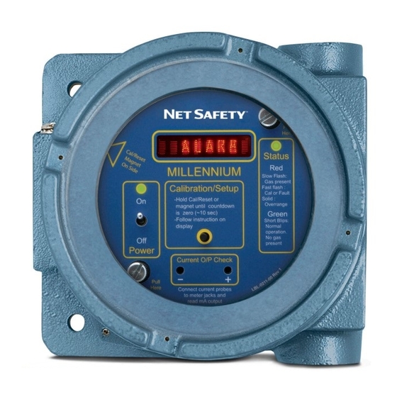
Operation Operation Millennium transmitter WARNING! Do not open the transmitter, sensor, or junction box enclosure when in a classified area or when an explosive atmosphere may be present unless the power to the transmitter has been removed. Figure 3-1 outlines the components on the Millennium transmitter and the subsequent paragraphs provide explanations for each component. -
Page 30: On/Off Switch
Operation 3.1.3 On/Off switch The On/Off switch is used to turn power on and off to the transmitter and sensor. Since the transmitter’s housing must be opened to access the On/Off switch, the area where the transmitter is located must be de-classified prior to using. 3.1.4 Setup button The Setup button provides access to the Millennium transmitter’s main menu, which in... -
Page 31: Indications And Outputs
Operation Indications and outputs Table 3-1: Transmitter indications State Current Output Status LED Display Main menu entered 3.0 mA Solid green Main menu items Normal operation 4.0 mA Green blip Clear Startup delay 3.0 mA Slow red flash Start delay Dirty optics 3.3 mA Fast red flash... -
Page 32: Particulate Alarm
Operation 3.3.3 Particulate alarm When particulate is present in the APM’s chamber, the message Alarm displays, the Status LED blips red, and the current output is 20.0 mA. If the relay has been set to non-latching, the unit will reset itself; if set to latching, a manual or remote reset is required to clear the alarm condition. -
Page 33: Current
Operation 3.6.2 Current A 4-20 mA dc current output is used to transmit the alarm status and fault conditions to other devices. This output can be wired for isolated or non-isolated operation. A 4.0 mA output indicates normal operation; a 20.0 mA output indicates that the alarm threshold has been exceeded. - Page 34 Operation...
-
Page 35: Chapter 4 Programming
Programming Programming Main menu The main menu provides access to various functional settings and viewing of current settings. The following options/settings are available in the main menu. • Set Zero • Sensitivity Settings • Review Relay Settings • Set Relay Options •... -
Page 36: Zero
Programming Important When the menu system has been entered, the current output will change to 3 mA. Ensure that external systems are bypassed, as required, prior to entering the menu system. 4.3.1 Zero If at any time the background particulate levels change, the transmitter may be zeroed to the new levels. -
Page 37: Sensitivity Settings
Programming Figure 4-1: Zero Level Setting 4.3.2 Sensitivity settings The APM can be set to detect low, medium or high sensitivity levels with high being the most sensitive. By default the sensitivity is set for high sensitivity from the factory. Follow the steps below to change the sensitivity. -
Page 38: Review Relay Settings
Programming 4.3.3 Review relay settings This is a read-only mode to provide a summary of the relay settings. Changes to the relay settings cannot be made in this menu item. Procedure Press and hold the Setup button or the magnet to the Reed switch to enter the main menu;... - Page 39 Programming To select that the relay be de-energized under normal conditions wait five (5) seconds for the next selection. If energized has been selected, a flashing YES will confirm the selection. To select that the relay be de-energized under normal conditions, press the Setup button or use the Reed switch to select this option.
- Page 40 Programming If the relay is setup as required, wait five (5) seconds for the next selection. If non- latching has been selected, a flashing YES will confirm the selection.
-
Page 41: Select Display Language
Programming 4.3.5 Select display language This section outlines how to change the main display language to English, Spanish, or French. Follow the steps below to change the display language. Press and hold the Setup button or the magnet to the Reed switch to enter the main menu;... - Page 42 Programming Figure 4-2: Programming flowchart...
-
Page 43: Chapter 5 Maintenance
Maintenance Maintenance Response check It is recommended that the APM be checked and tested at least once every three months. Spray Smoke Detector Tester (or equivalent product) in the direction of the sensor from a distance of two feet. Typically, a one to two second burst is adequate to initiate an alarm. When the alarm activates, the display will read Alarm, the Status LED will flash red, and the current output will be 20.0 mA to indicate detection of particulate matter or canned contaminant. -
Page 44: Troubleshooting
Maintenance Troubleshooting The Millennium Transmitter and APM Sensor are not designed to be repaired in the field. If a problem should develop carefully check for faulty wiring. If it is determined that the problem is caused by an electronic defect, the device must be returned to the factory for repair (refer to Section 1.2 Section 1.3... -
Page 45: Spare Parts And Accessories
Maintenance Spare parts and accessories Table 5-1: Spare Parts and Accessories Description Part Number Universal duct mount assembly with 1 m inlet sampling tube UDM-001 Universal duct mount assembly with 1.5 m inlet sampling tube UDM-002 Universal Duct Mount Assembly UDM-003 Magnet assembly MAGNET-1... - Page 46 Maintenance...
-
Page 47: Electrostatic Sensitive Device
Electrostatic sensitive device Electrostatic sensitive device Definition: Electrostatic discharge (ESD) is the transfer, between bodies, of an electrostatic charge caused by direct contact or induced by an electrostatic field. The most common cause of ESD is physical contact. Touching an object can cause a discharge of electrostatic energy. - Page 48 Electrostatic sensitive device...
-
Page 49: Wire Resistance Table
Wire resistance table Wire resistance table Distance AWG #20 AWG #18 AWG #16 AWG #14 Feet (Meters) 0.5 mm 0.8 mm 1.0 mm 2.0 mm 100 (30.5) 1.02 0.64 0.40 0.25 200 (61) 2.03 1.28 0.80 0.51 300 (91.4) 3.05 1.92 1.20 0.76... - Page 50 Wire resistance table...
-
Page 51: Chapter 8 Specifications
Specifications Specifications Electrical 8.1.1 Operating voltage range 10.5 to 32Vdc 8.1.2 Power consumption 3.24W max at 12 Vdc 3.6W max at 24 Vdc 8.1.3 Current output 4-20 mA into a maximum loop impedance of 800 Ohms at 32 Vdc or 150 Ohms at 10.5 Vdc isolated or non-isolated loop supply Environmental 8.2.1... -
Page 52: Metallurgy
Specifications 8.2.4 Metallurgy Aluminum (AL6061 - Sensor, A413 - Junction Box) Stainless steel (SS316) 8.2.5 Ingress protection Transmitter • Type 4X • IP66 IP67 (IECEx Stainless Steel) Junction Box • Type 4X • IP67 APM Sensor • Type 4X • IP65 8.2.6 Weight... -
Page 53: Separation
Specifications Separation Up to 2000 feet (610 meters) with 16 AWG (1.31 mm ) wire. Warranty Electronics: 3 years Sensors: 2 years... - Page 54 Specifications...
-
Page 55: Chapter 9 Certifications
Certifications Certifications North American hazardous locations 9.1.1 Transmitter Class I, Division 1, Groups B, C, and D T5 Class I, Zone 1 Ex d IIB+H T5 AL Version Only -40 °C ≤ Ta ≤ +75 °C Type 4X 9.1.2 APM Sensor Class I Division 1 Groups B, C, and D T5 Class I Zone 1 AEx db IIB+H T5 Gb... -
Page 56: Junction Box (Model Jb-Mpd)
Certifications 9.1.3 Junction box (Model JB-MPD) Class I, Division 1, Groups B, C, and D Class I Zone 1, AEx d/Ex d IIB+H -50 °C ≤ Ta ≤ +85 °C Type 4X, IP67 ATEX (-X model) 9.2.1 Transmitter 0575 II 2 G Ex d IIB+H T5, IP65 -40 °C ≤... -
Page 57: Junction Box (Model Jb-Mpd)
Certifications 9.2.3 Junction box (Model JB-MPD) 0575 II 2 G Ex d IIB+H -55 °C ≤ Ta ≤ +85 °C IP67 FM07ATEX0044 IECEx (-X model) 9.3.1 Transmitter (aluminum) Ex d IIB+H T5 Gb -40 °C ≤ Ta ≤ +85 °C Certificate Number: IECEx DNV 12.0014 IEC 60079-0: 2007-10/IEC 60079-1:2007-04 9.3.2... - Page 58 Certifications Consult the manufacturer if dimensional information on the flameproof joints is necessary. Follow the manufacturer's instructions to reduce the potential of an electrostatic charging hazard.
-
Page 59: Chapter 10 Ordering Information
Ordering information Ordering information Note Emerson Rosemount 6021 Innovation Blvd. Shakopee, MN 55379 Toll Free + 866 347 3427 F +1 952 949 7001 www.Emerson.com/FlameGasDetection... - Page 60 Ordering information...
- Page 61 Ordering information...
- Page 62 Ordering information...
- Page 63 Ordering information...
- Page 64 Linkedin.com/company/Emerson-Automation-Solutions twitter.com/rosemount_news Facebook.com/Rosemount youtube.com/RosemountMeasurement The Emerson logo is a trademark and service mark of Emerson Electric Co. Rosemount and google.com/+RosemountMeasurement Rosemount logotype are trademarks of Emerson. All other marks are property of their AnalyticExpert.com respective owners.
Need help?
Do you have a question about the Net Safety Millennium and is the answer not in the manual?
Questions and answers