
Related Manuals for Emerson Net Safety Millennium


Summary of Contents for Emerson Net Safety Millennium
- Page 1 Reference Manual 00809-0100-4077, Rev AB May 2018 ™ Net Safety Millennium Air Particle Monitor (APM) Oil Mist Detector...
- Page 2 Important instructions Because these products are sophisticated technical instruments, it is important that the owner and operation personnel must strictly adhere both to the information printed on the product nameplate and to all instructions provided in this manual prior to installation, operation, and maintenance.
- Page 3 Warranty Limited Warranty . Subject to the limitations contained in Section 2 (Limitation of Remedy and Liability) herein, Seller warrants that (a) the licensed firmware embodied in the Goods will execute the programming instructions provided by Seller; (b) that the Goods manufactured by Seller will be free from defects in materials or workmanship under normal use and care;...
-
Page 5: Table Of Contents
Contents Contents Chapter 1 Introduction ........................1 Models covered ..........................1 Service support ..........................1 Return of material ........................2 Product recycling/disposal ......................2 Chapter 2 Installation ........................3 Unpacking and inspection ......................3 Locate sensor ..........................4 Dimensions ..........................5 Mount ............................7 2.4.1 Duct mount ........................8 Wire ............................10 2.5.1 Field installation ...................... - Page 6 Contents 3.6.1 Relays ..........................26 3.6.2 Current ........................27 Net Safety APM Sensor .......................27 3.7.1 Sensor power up ......................27 3.7.2 Sensor communication ....................27 Chapter 4 Programming .......................29 Main menu ..........................29 Accessing the main menu ......................29 Using the main menu .........................29 4.3.1 Zero ..........................
-
Page 7: Chapter 1 Introduction
LEDs, it provides instructions and status alerts. The Net Safety APM Sensor is mounted where airborne particles are anticipated to accumulate, while the Net Safety Millennium Transmitter is located conveniently at eye level. The product is available in aluminum and stainless steel (SS). -
Page 8: Return Of Material
Purchase order, from your company, authorizing repairs or request for quote Procedure Ship all equipment, prepaid to: Emerson Automation Solutions 158 Edinburgh Ave Slough, United Kingdom SL 1 4UE Mark all packages with Return for Repair and include MRA number Pack items to protect them from damage and use anti-static bags or aluminum- backed cardboard as protection from electrostatic damage. -
Page 9: Chapter 2 Installation
Carefully remove all of the components from the packaging and verify them against the enclosed packing list. Inspect all components for any obvious damage such as broken or ™ loose parts. If you find any components missing or damaged, notify your local Emerson representative or the factory immediately. Figure 2-1 outlines the components supplied with the Net Safety APM. -
Page 10: Locate Sensor
Installation Locate sensor Prior to the installation process, develop a location plan for placing the Net Safety APM Sensor and Transmitter. Proper location of the Net Safety APM Sensor is essential for providing maximum protection. The most effective placement and number of detectors varies depending upon conditions. -
Page 11: Dimensions
2-3) or when connected directly to the 2-4). There are three (3) ¾ in. NPT conduit entries multi-purpose junction box (Figure available on the Net Safety Millennium Transmitter. Adapters for M20 and ½ in. NPT threads are also available as spare parts. Reference Manual... - Page 12 Installation Figure 2-3: Transmitter Dimensions ¾ in. FNPT cable entry ¾ in. FNPT cable Figure 2-4: Junction Box and Sensor Dimensions Millennium Air Particle Monitor...
-
Page 13: Mount
APM to ensure that external infrared light does not reach the sensing element. The Net Safety APM may be affected by sudden bursts of infrared light; therefore, Emerson recommends putting a time delay (between two [2] and five [5] seconds) into the monitoring system to prevent nuisance alarms. -
Page 14: Duct Mount
Installation Figure 2-5: Net Safety APM Mounting Locations APM sensor with junction box Movement of air particulate matter APM sensor with junction box Movement of air particulate matter 2.4.1 Duct mount Although the Net Safety Monitoring Air Particle Monitor has been proven to detect particulate matter travelling at speeds of up to 20 meters per second (65.62 feet per second), the detector is virtually unaffected by the velocity of particulate and air that it is exposed to. - Page 15 Installation Figure 2-6: Air Flow Drawing Duct surface Conduit to controller Junction box APM sensor UDM-001/UDM-002 duct mount Broken lines indicate direction of air flow. Direction of outlet air sample Outlet pipe Perforated sample draw tube (inlet pipe) Direction of air sample flow Reference Manual...
-
Page 16: Wire
If in doubt, consult a qualified official before wiring the system. When separating the sensor from the transmitter, Emerson highly recommends the use of shielded cable to protect against interference caused by extraneous electrical or electromagnetic noise to meet mandatory CE mark electromagnetic compatibility (EMC) requirements. -
Page 17: Sensor Separation
• Emerson recommends using explosion-proof drains and conduit breathers. In some applications, alternate changes in temperature and barometric pressure can cause breathing which allows moist air to enter and circulate inside the conduit. Joints in the conduit system are seldom tight enough to prevent this breathing. -
Page 18: Installation To Transmitter Or Junction Box
The sensor can be mounted in a number of configurations to ensure that air particulate will pass through the optical path of the sensor. Emerson recommends that the APM be mounted horizontally to ensure that build-up of dirt, dust, and debris will not affect the operation of the sensor. -
Page 19: Faceplate Rotation
2.5.6 Faceplate rotation In some applications, it is necessary for the Net Safety Millennium Transmitter to be mounted in a non-standard orientation. To accommodate such installations and ensure that the display will appear at the correct angle for viewing, you can rotate the PCB assembly inside the transmitter’s housing. -
Page 20: General Requirements
Installation Figure 2-9: PCB Assembly Rotated A. Horizontal mounting holes B. Faceplate C. Ribbon cable D. Standoffs E. PCB assembly F. Vertical mounting holes 2.5.7 General requirements WARNING! EXPLOSION Do not open the transmitter, sensor, or junction box enclosure when in a classified area or when an explosive atmosphere may be present unless the power to the transmitter has been removed. -
Page 21: Wiring Sensor To Transmitter
Installation Figure 2-10: Terminal Connection 2.5.8 Wiring sensor to transmitter Connect the sensor wires to the Net Safety Millennium Transmitter as shown in Figure 2-11. Table 2-2 outlines the wire colors and their purpose. Table 2-2: Sensor Wire Colors and Terminal Definition... - Page 22 Installation Figure 2-11: Millennium sensor wiring Terminal board +24 V 4-20 Shld APM sensor wires APM sensor Sensor board Sensor terminals Power terminals Millennium Air Particle Monitor...
-
Page 23: Wire Sensor To Junction Box
2.5.9 Wire sensor to junction box Sensor wiring side refers to wiring between the sensor and junction box. Transmitter wiring side refers to wiring between the Net Safety Millennium (MLP) Transmitter and junction box. Figure 2-12: Junction Box Wiring (Model JB-MPD) -
Page 24: Wiring Transmitter To Control System
Installation 2.5.10 Wiring transmitter to control system Connect the Net Safety Millennium Transmitter to the control system as shown in Figure 2-11. Table 2-5 outlines the terminal marking and their purpose. Table 2-5: Transmitter Connections Marking +24V 4-20 +VISO Function Remote reset 10.5-32 Vdc... -
Page 25: Non-Isolated And Isolated Power Configurations
Installation Note Unless otherwise specified, all models ship with this jumper in the non-isolated current position (Pin 2 and Pin 3 jumped). Refer to Figure 2-14. Figure 2-14: Jumper Locations Jumper positions to set power source for current output. Isolated and non-isolated current jumper - place jumper (shorting jack) over Pin 3 and Pin 2 (default position) for non-isolated configuration (source). - Page 26 Installation Figure 2-15: Detector Non-Isolated Configuration (Source) Isolated and non-isolated jumper pins Figure 2-16: Detector Non-Isolated Configuration (Sink) Isolated and non-isolated jumper pins Millennium Air Particle Monitor...
-
Page 27: Installation Checklist
Installation Figure 2-17: Detector Isolated Configuration (Source) Isolated and non-isolated jumper pins Figure 2-18: Detector Isolated Configuration (Sink) Isolated and non-isolated jumper pins Installation checklist Review the following checklist prior to turning the power on to the transmitter after installation has been completed: •... - Page 28 Installation • Ensure that proper shielding and grounding practices are adhered to and local codes are being followed. • Check system operational voltage and conditions and ensure that they are within the applicable specifications of the transmitter and sensor. • Verify wiring at all termination and junction points (transmitter, junction box, and power supply).
-
Page 29: Chapter 3 Operation
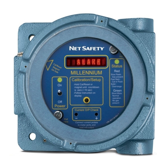
Figure 3-1 outlines the components on the Net Safety Millennium Transmitter, and the subsequent sections provide explanations for each component. Figure 3-1: Net Safety Millennium Transmitter Layout Section 3.1.1, Display... -
Page 30: Display
3.1.4 Setup button The Setup button provides access to the Net Safety Millennium Transmitter’s main menu, which in turn allows options to be reviewed and set. The Setup button is also used to zero the sensor. As the transmitter’s housing must be opened to access the button, the area must be de-classified before using. -
Page 31: Indications And Outputs
Alarms 3.3.1 Net Safety APM fault To ensure proper response, the Net Safety Millennium features self-testing circuitry that continuously checks for problems. When power is applied, the system automatically begins a test to ensure proper functionality. During normal operation, the transmitter continuously monitors the signal from the internal APM source. -
Page 32: Particulate Alarm
Section 3.4. Note The Net Safety APM may be affected by sudden bursts of infrared light; therefore, Emerson recommends that a time delay [between two (2) and five (5) seconds] be put into the monitoring system to prevent nuisance alarms. -
Page 33: Current
Safety APM Sensor is typically one hundred fifty (150) seconds. After the warm-up cycle has completed, the display reads Clear. As part of the self-diagnostic routine of the Net Safety Millennium Transmitter, the analog output outputs 20 mA on initial power up for a period not greater than 450 milliseconds. If routine power loss is expected on the system, take appropriate actions to limit false alarm conditions due to this diagnostic routine. - Page 34 Operation Millennium Air Particle Monitor...
-
Page 35: Chapter 4 Programming
3-1) to access the main menu. Using the main menu The following steps outline the actions required to navigate through the menu system. Refer to Figure 4-1 for the programming flow chart for the Net Safety Millennium Transmitter. Reference Manual... - Page 36 Programming Figure 4-1: Programming Flowchart Prerequisites Ensure that the transmitter is turned on and that no fault is present. If a fault is present, the menu system isn't accessible. Procedure Press and hold Setup or hold the magnet next to the triangle on the faceplate as shown in Figure 3-1 until the message Switch On displays and the countdown (10...
-
Page 37: Zero
Important After initial power-up, allow the unit to warm up for two to four hours before zeroing. If the sensor has been in operation for a period of time, Emerson recommends that you clean the window as outlined in Section 5.2. -
Page 38: Sensitivity Settings
Programming If your application has a constant level of particulate present that is required to be ignored by the APM you can set the zero level with the known particulate present as shown in Figure 4-2. To further fine tune the Net Safety APM response for your requirements, adjust the sensitivity settings accordingly. -
Page 39: Review Relay Settings
Programming The following three options display: Low Sensitivity YES? , Medium Sensitivity YES? and High Sensitivity YES? When the required setting is displayed, press Setup button or use the Reed switch to select. The selection is acknowledged with a flashing YES. 4.3.3 Review relay settings This is a read-only mode to provide a summary of the relay settings. - Page 40 Programming The flashing YES confirms this selection. After the Clean Window Alarm option has been chosen, the message Coil Status is displayed followed by Energized YES?. To select that the relay be energized under normal conditions, press Setup or use the Reed switch to select this option.
-
Page 41: Select Display Language
Programming To select that the relay be latched in its alarm state, press Setup or use the Reed switch to select this option. To select that the relay be non-latching, wait five (5) seconds for the next selection. If you selected Latching, a flashing YES confirms the selection. To select that the relay be non-latching, press Setup or use the Reed switch to select this option. - Page 42 Programming Millennium Air Particle Monitor...
-
Page 43: Chapter 5 Maintenance
Maintenance Maintenance Response check ™ ™ Emerson recommends that you check and test the Net Safety APM at least once every three months. Spray Smoke Detector Tester (or equivalent product) in the direction of the sensor from a distance of two feet. Typically, a one to two second burst is adequate to initiate an alarm. -
Page 44: Troubleshooting
(Return of material). Troubleshooting The Net Safety Millennium Transmitter and Net Safety APM Sensor are not designed to be repaired in the field. If a problem should develop, carefully check for faulty wiring. If it is determined that the problem is caused by an electronic defect, return the device to the factory for repair (refer to Section 1.2... -
Page 45: Electrostatic Sensitive Device
Electrostatic sensitive device Electrostatic sensitive device Electrostatic discharge (ESD) is the transfer, between bodies, of an electrostatic charge caused by direct contact or induced by an electrostatic field. The most common cause of ESD is physical contact. Touching an object can cause a discharge of electrostatic energy. - Page 46 Electrostatic sensitive device Millennium Air Particle Monitor...
-
Page 47: Wire Resistance Table
Wire resistance table Wire resistance table Distance AWG #20 AWG #18 AWG #16 AWG #14 Meters (Feet) 0.5 mm 0.8 mm 1.0 mm 2.0 mm 30.5 (100) 1.02 0.64 0.40 0.25 61 (200) 2.03 1.28 0.80 0.51 91.4 (300) 3.05 1.92 1.20 0.76... - Page 48 Wire resistance table Millennium Air Particle Monitor...
-
Page 49: Chapter 8 Specifications
Specifications Specifications Table 8-1: Electrical Specifications Specification Value Operating voltage range 10.5 to 32 Vdc Power consumption 3.24 W max at 12 Vdc 3.6 W max at 24 Vdc Current output 4-20 mA into a maximum loop impedance of 800 Ohms at 32 Vdc or 150 Ohms at 10.5 Vdc isolated or non-isolated loop supply Table 8-2:... - Page 50 Specifications Table 8-4: Weight Product Weight Transmitter Stainless steel: 7.0 lb (3.2 kg) APM sensor Stainless steel: 4.0 lb (1.8 kg) Junction box Stainless steel: 3.5 lb (1.6 kg) Separation Up to 610 meters (2,000 feet) with 16 AWG (1.31 mm ) wire Warranty Electronics: 3 years...
-
Page 51: Chapter 9 Certifications
Certifications Certifications North American hazardous locations 9.1.1 Transmitter Class I, Division 1, Groups B, C, and D T5 Class I, Zone 1 Ex d IIB+H T5 AL Version Only -40 °C ≤ Ta ≤ +75 °C Type 4X 9.1.2 APM Sensor Class I, Division 1, Groups B, C, and D T5 Class I, Zone 1, AEx db IIB+H T5 Gb... -
Page 52: Junction Box (Model Jb-Mpd)
Certifications 9.1.3 Junction box (Model JB-MPD) Class I, Division 1, Groups B, C, and D Class I Zone 1, AEx d/Ex d IIB+H -50 °C ≤ Ta ≤ +85 °C Type 4X, IP67 ATEX (-X model) 9.2.1 Transmitter 1180 II 2 G Ex d IIB+H T5, IP66 -40 °C ≤... -
Page 53: Junction Box (Model Jb-Mpd)
Certifications 9.2.3 Junction box (Model JB-MPD) 1180 II 2 G Ex d IIB+H -55 °C ≤ Ta ≤ +85 °C IP67 FM07ATEX0044 IECEx (-X model) 9.3.1 Transmitter (aluminum) Ex d IIB+H T5 Gb -40 °C ≤ Ta ≤ +85 °C Certificate Number: IECEx DNV 12.0014 IEC 60079-0: 2007-10/IEC 60079-1:2007-04 9.3.2... -
Page 54: Junction Box (Model Jb-Mpd)
Certifications IEC 60079-28:2015, 2nd Edition 9.3.4 Junction box (Model JB-MPD) Ex d IIB+H T5 Gb Certificate Number: IECEx FMG 14.0009X Consult the manufacturer if dimensional information on the flameproof joints is necessary. Follow the manufacturer's instructions to reduce the potential of an electrostatic charging hazard. -
Page 55: Chapter 10 Ordering Information
Optics Description Optical protection Separation Description Sensor separation Housing Description Stainless steel Approvals Description ATEX-IECEx Note Emerson Automation Solutions Rosemount 6021 Innovation Blvd. Shakopee, MN 55379 Toll Free +1 866 347 3427 F +1 952 949 7001 www.Emerson.com/FlameGasDetection Reference Manual... - Page 56 Ordering information Millennium Air Particle Monitor...
- Page 57 Ordering information Reference Manual...
- Page 58 Ordering information Millennium Air Particle Monitor...
- Page 59 Ordering information Reference Manual...
- Page 60 Facebook.com/Rosemount © 2018 Emerson. All rights reserved. youtube.com/RosemountMeasurement The Emerson logo is a trademark and service mark of Emerson Electric Co. Rosemount and google.com/+RosemountMeasurement Rosemount logotype are trademarks of Emerson. All other marks are property of their AnalyticExpert.com respective owners.
Need help?
Do you have a question about the Net Safety Millennium and is the answer not in the manual?
Questions and answers