Table of Contents
Advertisement
NOTE:
Please read all
instructions carefully
before using this product
Table of Contents
Safety Notice
Important Assembly
Information
Care and Maintenance
Parts List
Warranty
Ordering Parts
Model
ME-1019R
Retain This
Manual for
Reference
180501
OWNER'S
MANUAL
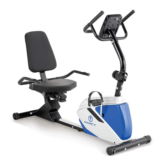
MAGNETIC RECUMBENT
IMPORTANT:
Please read this manual before commencing
assembly of this product.
2801 S. Towne Ave, Pomona, CA 91766
BIKE
ME-1019R
®
IMPEX
INC.
Tel: 800- 999-8899
www.marcypro.com
support@impex-fitness.com
Advertisement
Table of Contents

Related Manuals for Marcy ME-1019R


Summary of Contents for Marcy ME-1019R
- Page 1 NOTE: Please read all instructions carefully before using this product MAGNETIC RECUMBENT BIKE Table of Contents ME-1019R Safety Notice Important Assembly Information Care and Maintenance Parts List Warranty Ordering Parts Model ME-1019R Retain This Manual for Reference 180501 IMPORTANT: Please read this manual before commencing OWNER'S assembly of this product.
-
Page 2: Table Of Contents
EXERCISE GUIDELINES WARRANTY ORDERING PARTS BEFORE YOU BEGIN Thank you for selecting MARCY MAGNETIC RECUMBENT BIKE ME- ® 1019R by IMPEX INC. For your safety and benefit, read this manual carefully before using the equipment. As a manufacturer, we are committed to providing you with complete customer satisfaction. -
Page 3: Important Safety Notices
IMPORTANT SAFETY NOTICE This exercise equipment is built for optimum safety. However, certain precautions apply whenever you operate a piece of exercise equipment. Be sure to read the entire manual before you assemble or operate your equipment. In particular, note the following safety precautions: 1. -
Page 4: Warning Label Placement
WARNING LABEL PLACEMENT The warning labels shown here have been placed on the Base Frame. If the labels are missing or illegible, please call customer service at 1-800-999-8899 for replacements. Apply the labels in the location shown. © Impex Inc. www.marcypro.com... -
Page 5: Hardware Pack
HARDWARE PACK NOTE: The following parts are not drawn to scale. Please use your own ruler to measure the size. Description Q’ty Identifier Allen screw M8x⅝” Curved washer Φ¾” Carriage bolt M10x3” Domed nut M10 Leveling knob Quick release knob Flat washer Carriage bolt M10x1½”... -
Page 6: Components
COMPONENTS FOR ASSEMBLY Q’TY PART NO. DESCRIPTION Main frame Computer Seat support tube Sliding frame Front Stabilizer Rear Stabilizer Front post Pedal L/R Back Cushion Seat Cushion Handlebar Decorative cover L/R Sliding tube Bottle holder Stationary handlebar L/R © Impex Inc. www.marcypro.com... -
Page 7: Assembly Instructions
ASSEMBLY INSTRUCTION STEP 1 Attach the front stabilizer (#14) to the main frame (#1), securing with two carriage bolts (#13), two curved washers (#66) and two domed nuts (#19). 66 19 © Impex Inc. www.marcypro.com... - Page 8 STEP 2 Connect middle extension pulse wire (#63) to the rear extension pulse wire (#64). Attach sliding frame (#26) to main frame (#1), and tighten with six Allen bolts (#8) and flat washers (#27). Attach the leveling knob (#20) to the bottom of main frame (#1). 2.
- Page 9 STEP 3 1. Connect the upper extension sensor wire (#10) to the lower sensor wire (#12). 2. Connect the front extension hand pulse wire (#60) to the middle extension hand pulse wire (#63). 3. Connect the tension control cable (#7) to the extension tension cable (#11). 4.
- Page 10 HOW TO CONNECT TENSION CONNECTOR Slide the Cable wire from the extension sensor wire Connector in between the opening on the wire holder on sensor wire Connector. Pull the extension sensor wire Connector backward and slide the wire through the slot on the bracket. Drop down the Connector so the fitting sits firmly on top of the bracket.
- Page 11 STEP 4 1. Insert the sliding tube (#68) into seat support bracket (#25). Line up the holes and secure sliding tube (#68) with quick release knob (#24). 2. Attach seat pad (#32) to the seat support bracket (#25). Secure using four Allen bolts (#8). 3.
- Page 12 STEP 5 1. Attach the rear handlebar (#22) to the seat support bracket (#25). Secure using two carriage bolts (31), two curved washers (#9) and two domed nuts (#33). 2. Connect the rear extension hand pulse wire (#64) to the hand pulse wire (#65) on the rear handlebar. Tip: Avoid pinching the pulse Wires 3.
- Page 13 STEP 6 1. Attach bottle holder (#72) to the front post (#4). Secure using two self-tapping screws (#16). 2. Attach decorative cover L/R (#71L/R) to the sliding frame (#26). Secure using four self-tapping screws (#16) and one self-tapping screw (#61). ©...
-
Page 14: Exploded Diagram
EXPLODED DIAGRAM 66 19 © Impex Inc. www.marcypro.com... - Page 15 © Impex Inc. www.marcypro.com...
- Page 16 ME-1019R PARTS LIST Part Part Description Description Main frame Axle for flywheel Computer Nut M10 Philips Screw M5x⅜" Flywheel Front Post Bowl shaped spacer Flat washer Φ⅜" BB parts Screw M5x1½" Spacer Tension control knob Allen bolt M8x4" w/cable Allen bolt M8x⅝”...
- Page 17 Bearing Stationary handlebar L/R Bearing Aircraft nut M8 Copper washer Grommet COMPUTER FUNCTIONAL BUTTONS: MODE - Push down for selecting functions. SET - To set the time, distance, calories and hand pulse. RESET - For resetting time, distance, calories and hand pulse. FUNCTION AND OPERATIONS: 1.
-
Page 18: Exercise Guidelines
NOTE: 1. If the display is faint or does not show any digits, please replace the batteries. 2. The monitor will automatically shut off after 4 minutes of inactivity. SPECIFICATIONS: AUTO SCAN Every 6 seconds 00:00’~99:59’ TIME CURRENT SPEED The maximum signal can be pickup is 99.9M/H TRIP DISTANCE 0.00~99.99M or 0.00~9999M FUNCTION... - Page 19 2. The Exercise Phase This is the stage where you put the effort in. After regular use, the muscles in your legs will become more flexible. Work to your targeted heart rate but it is very important to maintain a steady tempo throughout.
-
Page 20: Warranty
® IMPEX INC. LIMITED WARRANTY ® IMPEX Inc. ("IMPEX ") warrants this product to be free from defects in workmanship and material, under normal use and service conditions, for a period of two years on the Frame from the date of purchase. This warranty extends only to the original purchaser.
Need help?
Do you have a question about the ME-1019R and is the answer not in the manual?
Questions and answers