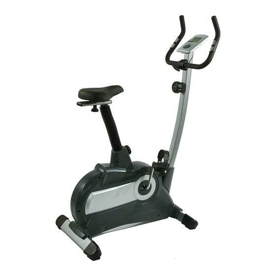
Summary of Contents for Marcy CL603
- Page 1 Cycle Product Code: CL603 Escalade International Limited Pleasant Road, Penllergaer, Swansea. SA4 9GE Tel: 00 44 1792 222 550 Fax 00 44 1792 895 781 www.escaladesports.co.uk info@escaladesports.co.uk 14-10-2009-1...
-
Page 2: Table Of Contents
Contents Important Safety Information Weight Limit Capacities Hardware Parts List Pre Assembly Check List Assembly Instructions 6 – 9 User Guide 10 – 11 Computer Instructions Exercise Instructions Fault Finding Chart Exploded Diagram Parts List Additional Information Care Maintenance Limited Warranty Supplied by Escalade International Ltd Pleasant Road... -
Page 3: Important Safety Information
IMPORTANT SAFETY INFORMATION READ ALL INSTRUCTIONS BEFORE USE THIS OWNER’S MANUAL CONTAINS ASSEMBLY, OPERATION, MAINTENANCE AND SAFETY INFORMATION. IN THE INTEREST OF SAFETY, PLEASE MAKE CERTAIN THAT YOU READ AND UNDERSTAND ALL THE INFORMATION BELOW. 1. This cycle is intended for class H (H=Domestic) use only. It is not designed for commercial use. 2. -
Page 4: Hardware Parts List
HARDWARE PARTS LIST Part No. Description Q’ty Metal cover for handlebar Plastic cover for handlebar ABS Flat washer ф7*ф12*1T Spring washer ф7*ф13*2T Allen Head Bolt M7*30 T knob M7x55L Steel bush ф7*ф12*25 Flat washer ф8*ф19*2T Allen Head Bolt M8*72 Allen key S6 Wrench 13/15 N-shape wrench 13/14/15 Above described parts are all the parts you need to assemble this machine. -
Page 5: Pre Assembly Check List
PRE-ASSEMBLY CHECK LIST NO.36 NO.45 NO.32 NO.01 NO.25 NO.47 NO.27 NO.23 NO.17 NO.06 Part No. Description Computer Handle bar Handle Bar Post Rear Stabilizer Pedal(R/L) Front Stabilizer Saddle Seat Post Bellows Main Frame... -
Page 6: Assembly Instructions
ASSEMBLY INSTRUCTIONS STEP 1 Attach the Front Stabilizer (27) to the Main Frame (47) using 2 Allen Head Bolts (26) and 2 Flat Washers (20). Attach the Rear Stabilizer (23) to the Main Frame (47) using 2 Allen Head Bolts (26) and 2 Flat Washers (20). - Page 7 HOW TO CONNECT TENSION CONNECTOR Slide the Cable wire from the Upper Tension Connector in between the opening on the wire holder on the Lower Tension Connector. Pull the Upper Tension Connector backward and slide the wire through the slot on the bracket. Drop the Connector down so the fitting sits firmly on top of the bracket.
- Page 8 STEP 3 Assemble the Handlebar (6) onto the bracket at the top of the Handlebar Post using 1 Clamp (7), Flat Washer (10), Spring Washer (9) and Allen Head Bolt (11). DO NOT FULLY TIGHTEN THE BOLT. Place the Plastic Cover (8) over the clamp assembly. Secure the handlebar clamp assembly using Flat Washer (10), Spring Washer (9), Steel Tube (13 and T Knob (12).
- Page 9 STEP 5 Assemble the left pedal (25L) to the left crank arm and the right pedal (25R) onto the right crank arm. Note: The pedals are marked with an L or R to distinguish each pedal. The Left Pedal uses a Left Hand Thread. Assemble the Pedal Straps marked L &...
-
Page 10: User Guide
USER GUIDE TRANSPORT TENSION CONTROL Decrease Increase... - Page 11 SEAT ADJUSTMENT FORE AND AFT To adjust the fore and aft position of the seat, loosen the club knob (38) beneath the seat and adjust to the desired position. Retighten club knob. HEIGHT To adjust the seat height, remove the Seat Adjustment Knob (38).
-
Page 12: Computer Instructions
COMPUTER INSTRUCTIONS FUNCTION 1. Scan: Automatically scans through each function in sequence so that you can see your progress without pressing the “mode” button each time. 2. Time: Automatically accumulate workout time when starting exercise. 0:00 – 99:99 Minutes 3. Speed: Display current speed during workout time. km/h 4. -
Page 13: Exercise Instructions
EXERCISE INSTRUCTIONS Using your MAGNETIC UPRIGHT CYCLE will provide you with several benefits, it will improve your physical fitness, tone muscle and in conjunction with a calorie controlled diet help you loose weight. 1. The Warm Up Phase This stage helps get the blood flowing around the body and the muscles working properly. It will also reduce the risk of cramp and muscle injury. -
Page 14: Fault Finding Chart
3. The Cool Down Phase This stage lets your Cardio-vascular System and muscles wind down. This is a repeat of the warm up exercise e.g. reduce your tempo, continue for approximately 5 minutes. The stretching exercises should now be repeated, again remembering not to force your muscles into the stretch. As you get fitter you may need to train longer and harder. -
Page 15: Exploded Diagram
EXPLODED DIAGRAM... -
Page 16: Parts List
PARTS LIST Description Q’ty NO Description Q’ty COMPUTER 41 SCREW 42 B.B. SET PULSE SENSOR WIRE END CAP 43 CHAIN COVER (R/L) NYLON LOCK NUT 44 CRANK ARM FOAM GRIP 45 BELLOW HANDLE BAR 46 MAGNETIC BRAKE SYSTEM METAL CLAMP 47 MAIN FRAME PLASTIC COVER FOR HANDLEBAR 48 SPRING FOR IDLER... -
Page 17: Additional Information
ADDITIONAL INFORMATION Packaging Disposal Government guidelines ask that we reduce the amount of waste material disposed of in land fill sites. We therefore ask that you dispose of all packaging waste responsibly at public recycling centres. End of Life Disposal We at Escalade hope you enjoy many years of enjoyable use from your Cycle. -
Page 18: Limited Warranty
LIMITED WARRANTY Escalade warrants this product to be free from defects in workmanship and material, under normal use and service conditions, for a period of one year from the date of purchase. This warranty extends only to the original purchaser. Escalade’s obligation under this Warranty is limited to replacing damaged or faulty parts at Escalade’s option.


Need help?
Do you have a question about the CL603 and is the answer not in the manual?
Questions and answers