Table of Contents
Advertisement
2
2
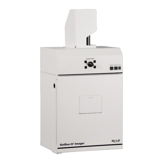
GelDoc-It
& ChemiDoc-It
Imagers
®
®
Installation and User Instructions
UVP, LLC
Ultra-Violet Products Ltd.
2066 W. 11th Street
Unit 1, Trinity Hall Farm Estate
Upland, CA 91786
Nuffield Road, Cambridge CB4 1TG UK
Phone: (800) 452-6788
Phone: +44(0)1223-420022
Fax: (909) 946-3597
Fax: +44(0)1223-420561
Web Site: www.uvp.com
1
81-0220-01 Rev R
Advertisement
Table of Contents

Related Manuals for UVP GelDoc-It2


Summary of Contents for UVP GelDoc-It2
- Page 1 UVP, LLC Ultra-Violet Products Ltd. 2066 W. 11th Street Unit 1, Trinity Hall Farm Estate Upland, CA 91786 Nuffield Road, Cambridge CB4 1TG UK Phone: (800) 452-6788 Phone: +44(0)1223-420022 Fax: (909) 946-3597 Fax: +44(0)1223-420561 Web Site: www.uvp.com 81-0220-01 Rev R...
-
Page 2: Table Of Contents
Table of Contents Basic information ....................4 User manual notes ..................4 Intended use ....................4 Technical data ....................5 Specifications .................... 5 Minimum computer requirements .............. 5 Cameras and lenses .................. 5 Safety instructions ..................... 7 General notes .................... 7 Safety Instructions –... - Page 3 Using the UV Gel Viewer Window ............24 Capturing Images and Using Templates ............25 Image Focusing ..................25 Capturing Images ..................26 Using Templates ..................27 Maintenance, replacement parts/accessories ..........29 Care and cleaning ................... 29 Replacement parts and accessories ............29 Troubleshooting ..................
-
Page 4: Basic Information
Basic information User manual notes The Imagers are intended for operation by qualified specialist personnel observing this user manual. The user manual informs about the design and function of the Imagers and provides the necessary know-how for the safe handling of the device and its components to personnel familiar with analysis. -
Page 5: Technical Data
Technical data Specifications Power Requirements 100/115V, 50/60Hz; 2.1 Amps at 120 Volts 230V, 50/60Hz; 1.1 Amps at 230 Volts Mains supply voltage fluctuations are not to exceed 10 percent of the nominal supply voltage Pollution Degree Installation Category Altitude Up to 2000 m Ambient Temperature 5 °C to 40 °C Humidity... - Page 6 Available are: CCD™ 515 or 815 CCD scientific-grade monochrome CCD camera. All cameras are Peltier cooled and offer full 16-bit file bit depth: The 515 CCD camera has 2.1 MP resolution with Peltier cooling to - 57 °C from ambient. The 515 CCD has a peak quantum efficiency of 50 % and is capable of binning from 1 x 1 to 8 x 8.
-
Page 7: Safety Instructions
Safety instructions General notes For your own safety, please read this chapter carefully before operating. Observe all safety notes listed in this user manual. Symbols and signal words used The user manual uses the following symbols and signal words to indicate safety hazards, warnings and instructions. -
Page 8: Safety Instructions - Operation And Maintenance
Safety Instructions – Operation and Maintenance The system is designed for function, reliability, and safety. The unit may include shortwave UV, which is a powerful source of UV radiation that will cause damage to unprotected eyes and skin. For your own safety observe the following notes: ... -
Page 9: System Design
System design System design Components Refer to the packing slip and pictured components for specific parts and components included with the system. Note: The delivered system may look slightly different (without cover, only with different camera bracket). ®2 ®2 GelDoc-It &... -
Page 10: Camera Models
Transilluminator Imagers can accommodate UVP’s Benchtop and FirstLight The GelDoc-It and ChemiDoc-It transilluminator models. UVP offers a variety of transilluminator configurations, including Benchtop models with multiple wavelengths and variable intensities as well as the highly ® uniform, patented FirstLight transilluminator. Refer to the packing slip for the transilluminator included with your system. -
Page 11: Optional Equipment
System design Optional Equipment UVP offers a variety of optional equipment to support the needs of varying laboratory environments. Refer to “Replacement Parts and Accessories” at the end of this manual for optional equipment part numbers. Thermal Printer The thermal printer provides archive quality, 256 gray- scale prints and five optional cost-effective print sizes. -
Page 12: Visionworks Acquisition And Analysis Software
System design ® 4.11 VisionWorks Acquisition and Analysis Software The Imager is configured with VisionWorks Software for acquisition and analysis of gels, plates and membranes. The software features image enhancement, complete analysis tools and reporting capabilities, and is ideal for users who require image analysis functions in addition to the standard image acquisition capabilities. -
Page 13: Set-Up
Set-Up Set-Up Scope of supply When unpacking the system, the following items will be included: GelDoc-It or ChemiDoc-It darkroom Transilluminator Camera with lens and bracket Ethidium bromide (EtBr) emission filter Power cables ® VisionWorks Software ... -
Page 14: Installing Emission Filters
5.4.1 Camera with Manual Lens The 515 camera, zoom lens and diopter are assembled at the UVP factory. Note: The camera, lens and brackets may appear different than pictured. Before installing the camera, install the emission filter. Refer to section: 5.3 Installing emission filters. - Page 15 Set-Up Using the brass thumb nuts provided, secure the camera assembly bracket to the dark- room base located the top of the system. Ensure that a light-tight seal is made between the end of the lens and the rubber gasket beneath the darkroom bracket. Plug the additional power cables to an external power source.
- Page 16 5.4.2 Camera with Motorized Lens The 515 camera, zoom lens and diopter are assembled at the UVP factory. Note: The camera, lens and brackets may appear different than pictured. The 815 CCD and and 515 CCD cameras use many of the same components and are in- stalled in a similar manner.
- Page 17 Set-Up 1. Check to see if base mount has been mounted to the top of the darkroom. If not, use the black screws or brass thumb nuts to install the mount. 2. Attach the camera bracket to the base mount with the brass thumb nuts. 3.
- Page 18 515 CCD Camera with Motorized Zoom Lens Note: The picture below shows the 12.5-75mm f/1.2 motorized zoom lens. The camera, zoom lens and diopter are assembled at the UVP factory. Note: The camera, lens and brackets, may appear different than pictured.
- Page 19 Set-Up 4. Mount the lens control box on the hook located at the back of the darkroom. Hook for the Lens Control Box 5. Plug the serial cable from the motorized lens into the lens control box. Power switch for the Lens Control Box 6.
-
Page 20: Software Installation
Activation can also be done at REG.UVP.com using any other web connected device. A Config ID will be needed for this option and can be found by clicking Next after selecting On the fly activiation. It will be displayed under Configuration ID. -
Page 21: Installing Camera Drivers
Software Installation 8. If the computer is not connected to the Internet, click Offline activation to register the software. This allows the user to obtain the activation code and enter it at another time. 9. Click Next to continue. 10. Click the link provided and complete the form to obtain registration instructions. Click Finish. Installing Camera Drivers 1. -
Page 22: Using The Imaging System
Using the imaging system Using the imaging system Powering up the system Once plugged in to a surge-protected wall outlet, the system is always powered on. Power to specific system components, including overhead and transillumination lighting, is con- trolled by switches located on the front of the unit. If using the system with a motorized zoom lens, turn on the power switch for the Lens Control Box (see “Camera Setup”... -
Page 23: Using The Filters
Using the imaging system Using the Filters When installing emission filters in the system, the user should note the location of the emission filter selector knob located on the front of the system (pictured below). To change to a different filter, turn the filter selector knob to the desired location. Ensure that the knob clicks into place to verify that the filter is positioned correctly. -
Page 24: Using The Uv Gel Viewer Window
Using the UV Gel Viewer Window The UV Gel Viewer Window, built into the darkroom door, allows users to view the interior of the darkroom without opening the entire darkroom door. To open the Window, press firmly on the top of the Window cover to release the pressure- sensitive clasp and open the viewer. -
Page 25: Capturing Images And Using Templates
Capturing Images and Using Templates Image Focusing 8.1.1 Manual Lens Prior to capturing an image, prepare the image focus: Turn on the transilluminator and place the Fluorescent Focus Target (see “System Components”) on the transilluminator surface. NOTE: The darkroom has a UV safety switch that turns off the transilluminator and op- tional UV handheld lamps when the door is open. -
Page 26: Capturing Images
8.1.2 Motorized Lens (815 CCD and 515 CCD) Prior to capturing an image, prepare the image focus: Turn on the transilluminator and place the Fluorescent Focus Target (see “System Components”) on the transilluminator surface. NOTE: The darkroom has a UV safety switch that turns the transilluminator and optional UV handheld lamps off when the door is open. -
Page 27: Using Templates
8.2.2 Capturing Longer Image Exposure with the Least Noise Binning can be ideal for very dim images where high sensitivity is needed. Binning of at least 2 x 2 is recommended for exposures over 1 - 2 minutes. Ensure that the camera has had an adequate amount of time to cool before taking long exposure images. - Page 28 8.3.2 To Process a Blot Place the Western blot on a hinged transparency or in clear plastic bag. Position the blot on the black chemi tray. Pre-focus and position the blot with the lights off, the door cracked open and the lens set to the fastest f-stop (the lowest aperture number).
-
Page 29: Maintenance, Replacement Parts/Accessories
For replacement parts of the transilluminator please refer the manual of the transilluminator. For replacement parts or components not shown here, please call UVP Customer Service or place of purchase. Please have the model number available when you call. - Page 30 Maintenance, replacement parts/accessories Filter, SYBR Gold, 50mm Square 38-0221-01 Transillumination Accessories: LED White Light Plate 95-0476-01 White Light Converter Plate, 21x26cm 38-0191-01 Visi-Blue Converter Plate, 21x26cm 38-0200-01 Gel Accessories: Gel-Cutter 85-0002-01 Gel-Ruler 85-0003-01 Gel-Scooper 85-0006-01 Gel-Tray, small 85-0007-01 Gel-Sentry DNA Preparation Plate 97-0076-01 Fluorescent Standard Step Tablet 33-0014-02...
- Page 31 Maintenance, replacement parts/accessories 81-0220-01 Rev R...
-
Page 32: Troubleshooting
Windows, please contact your sys- tem administrator for assistance. If an error message appears repeatedly and your system administrator does not recognize it as a Microsoft Windows error, contact UVP Technical Support for further assistance. Disposal At the end of its service life the Imaging System and all its electronic components must be disposed of in accordance with the applicable regulations as electronic waste.
Need help?
Do you have a question about the GelDoc-It2 and is the answer not in the manual?
Questions and answers