Badger Meter ModMAG M2000 User's Installation And Operation Manual
Hide thumbs
Also See for ModMAG M2000:
- Installation and operation manual (48 pages) ,
- User manual (32 pages) ,
- Connecting manual (2 pages)

Related Manuals for Badger Meter ModMAG M2000


Summary of Contents for Badger Meter ModMAG M2000
- Page 1 Badger Meter Europa GmbH ® ® ModMAG M2000 INSTALLATION AND OPERATION MANUAL July 2018 MID_M2000_BA_02_1807...
-
Page 2: Table Of Contents
Contents Page 1. Basic safety precautions ....................1 2. System description ......................2 3. Installation ........................3 General information ....................3 3.1.1 Temperature ranges ..................3 3.1.2 Protection class ..................... 3 3.1.3 Transport ....................... 4 Installation ....................... 4 3.2.1 Meter orientation ................... 4 3.2.2 Inlet and outlet pipe .................. -
Page 3: Basic Safety Precautions
Basic safety precautions Page 1/51 1. Basic safety precautions Before installing or using this product, please read this instruction manual thoroughly. Only qualified personnel should install and/or repair this product. If a fault appears, contact your distributor. Installation Do not place any unit on an unstable surface that may allow it to fall. Never place the units above a radiator or heating unit. -
Page 4: System Description
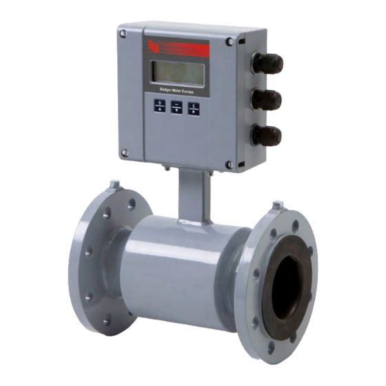
System description Page 2/51 2. System description The electromagnetic flow meters are intended for the metering of all fluids with electric conductivity of at least 5 µS/cm (20 µS/cm for demineralized water). These series of meters is characterized by a high degree of accuracy. Measuring results are independent of density, temperature and pressure. -
Page 5: Installation
Installation Page 3/51 3. Installation • Warning: Installation instructions given in the following are to be observed in order to guarantee a perfect functioning and a safe operation of the meter. 3.1 General information 3.1.1 Temperature ranges • Caution: In order to prevent a damaging of the meter, you are requested to strictly observe amplifier’s and detector’s maximum temperature ranges. -
Page 6: Transport
Installation Page 4/51 3.1.3 Transport Caution: • Use lifting lugs when lifting meter flow tubes that are 150 in diameter or larger. • Do not lift meter on measuring amplifier or on detector’s neck. • Do not lift meter with a fork lift on the jacket sheet. This could damage the body. -
Page 7: Meter Location
Installation Page 5/51 3.2.3 Meter location Caution: • Do not install the detector on the suction sides of pumps. This could damage the liner (in particular PTFE liners). • Verify that the pipeline is always filled on the measuring point, if not - a correct or accurate measurement is not possible. -
Page 8: Pipe Reducer Requirements
Installation Page 6/51 3.2.4 Pipe reducer requirements With pipe reducers as per DIN 28545 detectors can be mounted in larger pipelines. You can determine the occurring pressure drop by using the shown nomogram (only applicable to liquids with similar viscosity like water). •... -
Page 9: Separate Version
Installation Page 7/51 3.2.5 Separate version Provide a separate version in the following cases: • Note: Detector protection class IP 68 • Fluid temperature > 100 °C • Strong vibrations Caution: • Do not install the signal cable close to power cables, electric machines, etc. -
Page 10: Plastic Or Lined Pipelines
Installation Page 8/51 "X" M4:1 "X" 3.2.7 Plastic or lined pipelines If non-conductive pipelines or pipelines lined with non-conductive material are used, install an additional grounding electrode or grounding rings between the flanges. Grounding rings are installed like gaskets between the flanges and are connected with a grounding cable to the meter. -
Page 11: Electrically Disturbed Environment
Power connections Page 9/51 3.2.9 Electrically disturbed environment If the pipe material is in an electrically disturbed environment or if metallic pipelines that are not grounded are used, we recommend a grounding as shown in the following picture in order to assure that measurement is not influenced. 6 mm²... -
Page 12: Separate Version
Close device and connection cover again To Amplifier Detector firmly. 13 SHIELD Shield 13 12 COIL COIL 12 COIL 11 11 COIL Badger Meter JBOX - PRIMO REMOTE - REV1 Terminal box – Terminal M2000 Description Wire color Standard Stainless steel Coil 1... -
Page 13: Signal Cable Specification
Page 11/51 4.2.1 Signal cable specification • Note: Only use signal cables delivered by Badger Meter or corresponding cable in accordance with the following specification. • Take max. signal cable length between detector and amplifier into account (keep distance as low as possible). -
Page 14: Configuring Input/Output (I/O)
Power connections Page 12/51 4.3 Configuring input/output (I/O) Fuse Auxiliary power Display Displ Coil detector Jumper JP1 Jumper JP2 DISPLAY Electrodes detector COMMUNICATION Memory token Communication Input/Output Description Terminal 0 - 20 mA Analog output 16 (+) 4 - 20 mA RL <... -
Page 15: Communication Interfaces
Power connections Page 13/51 4.4 Communication interfaces M2000 offers following communication interfaces: • Modbus ® RTU RS485 • M-Bus • HART • Profibus DP The additional interface board is already plugged in by the manufacturer or can be ordered and easily plugged in afterwards. The interface board is plugged in to the 11 pin connector at the lower right of the main board. -
Page 16: Programming
Programming Page 14/51 5. Programming The LCD display with 4 lines and 20 digits shows following information: Line Uni-directional Bi-directional Meter type, software version and alternating error messages Flow velocity (v) Flow rate (R) Totalizer T1 Totalizer T+ Totalizer T2 Totalizer T- Pre-selection volume (PS) Net. -
Page 17: Quick Setup
Programming Page 15/51 5.1 Quick setup The M2000 amplifier provides you with a quick setup utility that allows you to quickly set most of the important parameters like flow units, totalizer units, full scale flow and low flow cutoff settings. Flow Units Flow units let you select among the flow units mentioned below. - Page 18 Programming Page 16/51 Low Flow Cut-off Low Flow Cut-off defines the threshold at which flow measurement will be forced to zero. The cutoff value can be from 0 % to 9.9 % of the full scale flow. Increasing the threshold will help prevent false reading during “no flow”...
-
Page 19: Main Menu
Programming Page 17/51 5.2 Main menu The following menu items are available to you in the main menu: • Meter setup • Measuring • Inputs and outputs • Reset of the totalizer • Setting of communication port • Specific counter settings •... -
Page 20: Measurement
Programming Page 18/51 This figure is used for setting pipe’s diameter (size). Several sizes DN 6 Pipe Diameter to DN 2000 as well as specific sizes in [mm] can be set. Note: Pipe diameter is set at the factory. Changes of size have an impact on meter’s accuracy. - Page 21 Programming Page 19/51 5.2.2 Measurement Totalizer Unit This parameter establishes the units of measure for the totalizers: Unit Unit Liters Imperial Gallons HectoLiter Mega Imp. Gal. M³ Cubic Meters Pounds Cubic Feet Fluid Ounces U.S. Gallons Acre Feet MegaGallons Barrel MID_M2000_BA_02_1807...
- Page 22 Programming Page 20/51 Full Scale Flow This parameter sets the maximum flow the system is expected to measure. This parameter has influence on other system parameters. These parametes include: Frequency output and current output. In terms of flow velocity, the meter’s limit are from 0.1 to 12 m/sec. Moreover the values for Low Flow Cutoff and meter’s limits monitoring depend on Full Scale Flow.
-
Page 23: Inputs And Outputs
Programming Page 21/51 5.2.3 Inputs and outputs Analog output Range This parameter establishes the range of the analog output signal: 0 to 100% (= full scale). The following current ranges are available to you: Current output 0 to 20 mA 4 to 20 mA 0 to 10 mA 2 to 10 mA... - Page 24 Programming Page 22/51 5.2.3 Inputs and outputs Digital input lets you reset totalizers, batches, interrupt flow Digital Input measurement (Positive Zero Return) or set to ADE. Input switching (by a normally open contact) is provided by applying an external potential of 5 to 30 VDC or by an internal voltage source of 24 VDC via output #2.
- Page 25 Programming Page 23/51 5.2.3 Inputs and outputs Digital Outputs In the sub-menu “Functional operation“, you can configure functional operation of the 4 digital outputs. You can select e.g “forward pulse” for the digital output and define the pulses per totalizer unit via “pulse scale”.
- Page 26 Programming Page 24/51 Digital Outputs Digital outputs 3 and 4 The two outputs can be operated as open collector and as relay (solid state relais SSR). You can select operating mode by programming the relative outputs (output hardware). Output #3 Solid state relais max.
- Page 27 Programming Page 25/51 Digital Outputs Functional The following functions can be selected for the outputs selection 1 to 4: Function Dig1 Dig2 Dig3 Dig4 Inactive Forward pulse Reverse pulse AMR (50 ms) Frequency output Flow set point Empty pipe alarm Flow direction Preset output Error alarm...
- Page 28 Programming Page 26/51 Pulses/Unit The Pulses/Unit parameter lets you set how many pulses per unit of measure will be transmitted. The configurable range is from 0.0001 to 99.999 pulses/ volume unit, however the max. output frequency of 10,000 pulses/sec. (10 kHZ) must not be exceeded. Pulse Width This parameter establishes the “On”...
-
Page 29: Clear Totals
Programming Page 27/51 Flow Simulation provides analog and digital output simulation based on Flow Simulation a percentage of the full scale flow in cases where no real flow is occurring. The range of simulation includes -100% to +100% in steps of 10% of the full scale flow. -
Page 30: Communications
Primo 3.x is the emulation of the former Primo amplifier interface. Flow Diagnostic is a service tool that allows Badger Meter to acquire data from the device about the flow velocity measurements. When enabled, every flow velocity measurement is transmitted in ASCII form out the serial port and can be logged on a PC with a special program (hyperterminal or similar). - Page 31 Programming Page 29/51 5.2.5 Communications Stop Bits The following stop bits are supported: • 1 Stop Bit • 2 Stop Bits Default setting is [1 Stop Bit] Port B This interface is for the internal communication between the main board ®...
-
Page 32: Advanced
Programming Page 30/51 5.2.6 Advanced Datalogger Note: For this feature is a special memory card necessary (blue memory token) which will pluged in into a memory slot on the main board. This is optional and will be not delivered with the common product. First adjust the system clock before programing the interval time otherwise the data logging records have the wrong time stamps. - Page 33 Programming Page 31/51 5.2.6 Advanced Configuration Token properties • Write protection (ON/OFF) • Power on load (ON/OFF) • On time load (ON/OFF) Parameter Selection • Group 0 (ALL) • Group 1 (User) • Group 2 (PRV) • Group 3 (FACT) •...
- Page 34 Programming Page 32/51 5.2.6 Advanced Totalizer This function lets you define totalizers’ formatting. You can select among Resolution the following formats: Format 0.0001 0.001 0.01 1000 With this function, the best possible resolution is automatically chosen. For example: 7-dial and resolution 0.001 is indicated 1234.567 m³/h 7-dial and resolution 0.1 is indicated 123456.7 m³/h...
- Page 35 Programming Page 33/51 5.2.6 Advanced Software Filter MDN-Filter The Median filter smoothes out short-term fluctuations. The filter level can be adjusted from S0 (off) to S9. ACC-Filter This filter is intended to help eliminate unrequested peaks during measurement. Activation Activates or deactivates the software filter Filter Delay Filter Delay lets you set the amount of time that the flow will be held constant once the filter is activated...
- Page 36 Programming Page 34/51 5.2.6 Advanced Empty Pipe Cal. Note: To compensate different fluid conductivity, signal cable lengths or sizes during measurements, you can calibrate them accordingly. This is important in case that fluid monitoring has been activated and “empty pipe” is signalized although the pipe is filled. Proceed as follows: 1.
-
Page 37: Info/Help
Programming Page 35/51 5.2.7 Info/Help Error Counts The following list gives you an overview about the kind and frequency of various messages and hence provides a diagnostic of the counter or the measuring point. Prior to any diagnostic, we suggest to reset the individual parameters in order to exclude impacts occurring due to installation, maintenance or other anormal operation conditions. - Page 38 Programming Page 36/51 PowerUp The number of times that the unit has been powered on. Counter Power Off The totalizer accumulates the time during which the device is switched Totalizer OFF. This time can be reset by the function “Reset Totalizer -> Tpwroff“ Version info The current software version of the unit.
-
Page 39: Troubleshooting
Troubleshooting Page 37/51 6. Troubleshooting Error messages can be displayed via the 4 digital outputs. By means of the error list type and frequency of the errors can be logged and analysed, also see chapter Programming: Info/Help. Menu Manager Configuration Errors Error Description Recommended Action... - Page 40 Troubleshooting Page 38/51 The following error messages can be displayed: Description Possible Cause Recommended Action Meter not connected. Err: Coil Check if meter is connected and make Connection to meter interrupted. sure that cable connection is not interrupted. ...
-
Page 41: Replacing The Fuse
Troubleshooting Page 39/51 6.1 Replacing the fuse • Warning: Disconnect main power to the unit before replacing the fuse. Fuse Fuse type: T2 H 250 V (2A idle) 6.2 Replace meter’s electronics • Warning: Disconnect auxiliary power before opening body cover. DISPLAY Coil plug Electrode plug... -
Page 42: Technical Data
Technical data Page 40/51 7. Technical data 7.1 Detector Type II Technical data Size DN 6 – 2000 (1/4“...80“) Process connections Flange: DIN, ANSI, JIS, AWWA etc. Nominal pressure Up to PN 100 Protection class IP 67, IP 68 optional Min. - Page 43 Technical data Page 41/51 ANSI flanges DIN flanges A Std* ∅ D ∅ K ∅ d2xn ∅ D ∅ K ∅ d2xn ISO** 1/4” 88,9 60,3 15,9 x 4 14 x 4 5/16” 88,9 60,3 15,9 x 4 14 x 4 3/8”...
-
Page 44: Detector Type Food
Technical data Page 42/51 7.2 Detector type Food Technical data Size DN 10 – 100 (3/8“...4“) ® Process connections Tri-Clamp , DIN 11851, ISO 2852, etc. Nominal pressure PN 10 Protective class IP 65, IP 68 optional Min. conductivity 5 µS/cm (20 µS/cm demineralized water) Liners PTFE -40 to +150°C... - Page 45 Technical data Page 43/51 ® Process connection Tri-Clamp Process connection DIN 11851 ® ® M2000 mounted version M2000 mounted version ® Type Food Tri-Clamp Type Food Milk Pipe DIN 11851 3/8” 1/2” 3/4” 1” 1 ½“ 2” 2 ½“ 3” 4”...
-
Page 46: Detector Type Iii
Technical data Page 44/51 7.3 Detector Type III Technical Data Size DN 25 – 100 (1“...4“) Process connections Sandwich connection, (intermediate flange mounting) Nominal pressure PN 40 Protective class IP 67, IP 68 optional Min. conductivity 5 µS/cm (20 µS/cm demineralized water) Liner PTFE -40 to +150°C... -
Page 47: Meter Type M2000
Technical data Page 45/51 7.4 Meter type M2000 Technical data Type M2000 Auxiliary power 85 – 265 VAC, 45 – 65 Hz Optional 9 - 36 VDC 0/4 – 20 mA, ≤ 800 Ohm Analog output Flow direction is displayed via separate status output Digital outputs 4 freely configurable open collector outputs Active 24 V, 50 mA or Passiv 30 VDC, 100 mA... -
Page 48: Error Limits
Technical data Page 46/51 7.5 Error limits Measuring range 0,03 m/sec. to 12 m/sec. Pulse output ±0,2% of m.v. ±1 mm/s Similar to pulse output plus ±0,01 mA Analog output ±0,1% Reproducibility Reference conditions: Ambient and fluid temperature 20°C > 300 µS/cm Electr. -
Page 49: Size Select
Technical data Page 47/51 7.6 Size select DN 6 - DN 100 0,01 0,01 1.000 10.000 L/min DN 125 - DN 1400 0,01 1000 10.000 100.000 m³/h MID_M2000_BA_02_1807... -
Page 50: Program Structure
Program structure Page 48/51 8. Program structure Start Menu Quick Setup Flow Unit Totalizer Unit Full Scale Flow Low Flow Cutoff Main Menu Meter Setup Scale Factor Empty Pipe Detect Power Line Freq Excitation Freq Pipe Diameter Detector Factor Detector Offset Measurements Velocity Unit Flow Unit... - Page 51 Program structure Page 49/51 Start Menu Main Menu Inputs/Outputs Digital Output #3 Full Scale Freq Preset Amount Set Point Min. Set Point Max. Normally Open Output Type Normally Closed Hardware Select Relay Open Collector Select Funtion None Frequency Output Flow Set Point Empty Pipe Alarm Flow Direction Preset Output...
-
Page 52: Spare Parts
Spare parts Page 50/51 9. Spare parts Pos. Description Part n° 85-265 VAC Amplifier assembly complete 592500 9-36 VDC Amplifier assembly complete 592501 85-265 VAC Board 384619 9-36 VDC Board 384623 Housing 384615 LCD display 384602 Display window 384612 Cable gland 382859 Buttons kit black 384610... -
Page 53: Return Of Goods For Repair / Harmlessness Declaration
Return of goods for repair / Harmlessness declaration Page 51/51 10. Return of goods for repair / Harmlessness declaration Please refer to our claims return form/harmlessness declaration under www.badgermeter.de/service/return of goods. MID_M2000_BA_02_1807... - Page 54 MID_M2000_BA_02_1807...
- Page 55 MID_M2000_BA_02_1807...
- Page 56 Hotline Phone +49-7025-9208-0 or -30 +49-7025-9208-15 Badger Meter Europa GmbH ® Subsidiary of Badger Meter, Inc., USA Nürtinger Strasse 76 72639 Neuffen (Germany) E-mail: badger@badgermeter.de www.badgermeter.de...
Need help?
Do you have a question about the ModMAG M2000 and is the answer not in the manual?
Questions and answers