Badger Meter M-series Installation And Operation Manual
Hide thumbs
Also See for M-series:
- Installation and operation manual (56 pages) ,
- Connecting manual (2 pages)

Related Manuals for Badger Meter M-series


Summary of Contents for Badger Meter M-series
- Page 1 IMPORTANT !!!! Read this manual before attempting any handling or installation of the meter. BME-M3000-09-07...
-
Page 2: Disclaimer
However, no responsibility is assumed for inaccuracies, nor does Badger Meter Europe assume any liability arising out of the application and use of the equipment described. Should the equipment be used in a manner not specified by Badger Meter Europe, the protection provided by the equipment may be impaired. -
Page 3: Basic Saftey And Repair Advise
EMC regulation 2004/108/EC and PED regulation 97/23/EC. The device is so designed and manufactured that it cause no danger by direct or indirect contact. Badger Meter Europe confirm the conformity with the European regulations by printing the CE sign on the meter. -
Page 4: Table Of Contents
TABLE OF CONTENTS Disclaimer Questions or Service Assistance Product Identification Information Basic saftey and repair advise CE mark SAFETY PRECAUTIONS and INSTRUCTIONS Equipment Unpacking, Inspection, Moving and Return Policies Rigging, Lifting, Moving Large Units Instructions Specific to Hazardous Area Installations METER DESCRIPTION Empty Pipe Detection Amplifier Mounting Options... - Page 5 ADDENDUM A Detector Specifications Amplifier Specifications ADDENDUM B Maintenance Flow Tube and Electrode Cleaning Fuse Replacement Amplifier PCB Stack Replacement ADDENDUM C Menu Structure Flow Chart ADDENDUM D ATEX Certificate...
-
Page 6: Safety Precautions And Instructions
Within 48 hours of delivery request an inspection report from the carrier. File a claim with the carrier. Contact the Badger Meter factory to facilitate repair or replacement, +49 7025 92080. 7. All detectors with PTFE liners are shipped with a liner protector to maintain proper form of the PTFE material during shipping and storage. -
Page 7: Instructions Specific To Hazardous Area Installations
Instructions Specific to Hazardous Area Installations These instructions apply to equipment covered by ATEX Use the sling-rigged method to lift large detectors into a Certificate Number FM08ATEX0051X issued by FM. vertical position while still crated. Use this method to position large detectors vertically into pipelines. - Page 8 Certification markings are noted on the product label. For additional information regarding importation, equipment installation, equipment repair, equipment return or renewal parts, please contact Badger Meter Europe or your local Badger Meter representative. Meter mounted 85-240 VAC Meter mounted 24 VDC...
-
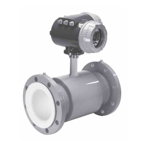
Page 9: Meter Description
METER DESCRIPTION Badger Model M3000 electromagnetic meters are ATEX This configuration can also provide a more convenient approved for Zone 2 hazardous locations. To achieve amplifier programming and display placement for monitoring hazardous location ratings electrodes in the flow tube are meter readings. -
Page 10: Pipelines And Fluid Flow
4. For meter mounted amplifier applications, the fluid Horizontal Placement temperature range is 32°F to 178°F (0°C to 80°C) at a In a horizontal piping orientation, mount the detector to maximum ambient temperature of 122°F (50°C) for the piping with the flow measuring electrode axis in a horizontal following liner materials: Hard rubber. -
Page 11: Chemical Injection Applications
Sometimes it’s difficult to specify the exact downstream placement distances because of the number of variables. Contact Badger Meter Technical Support, +49 7025 92080, to review your application if necessary. Partially Filled Pipe Situations It is possible to encounter situations where the process pipe is momentarily only partially filled. -
Page 13: Remote Mount Amplifier
For Remote Mount Units consider: 1. Amplifier location. 2. Remote amplifier mounting bracket. 3. Proper conduit and conduit fittings. 4. Wiring and conduit locations. REMOTE MOUNT AMPLIFIER NOTE: Screws are supplied to attach bracket to amplifier. Screws are not supplied to attach bracket at mounting location. -
Page 15: Electrode And Coil Wiring From Detector Junction Box To Remote Mount Amplifier Junction Box
Electrode and Coil Wiring From Detector Junction Box Electrode Wiring in Amplifier Junction Box To connect the electrode wires in the Amplifier Junction Box: to Remote Mount Amplifier Junction Box A remote mount unit requires electrode and coil cables, from 1. - Page 16 OUTPUT WIRING The Badger M3000 Meter converts liquid flow into electrical signal(s). With proper output wiring and amplifier programming, the signal(s) are sent to, and used by, processing equipment used in operations or other procedures. NOTE: Output wires and terminals are the same for meter mount or remote mount meters Output wiring requires 18 to 22 AWG maximum, shielded wire (not supplied).
-
Page 17: Output Wiring
Amplifier Output Wire Terminal Block Connections: Analog Input Wiring Diagram Reference Control Signal Wiring Diagrams on next two pages. Function: 4-20 mA, 0-20mA, 0-10mA Analog Output (Loop voltage = 18VDC Sourced) mA Analog Output (+) 5 Common 6 Output 1 - Transistor Output (open collector) Functions: Forward Pulse, AMR Pulse, Flow Set Point, Error Alarm, Empty Pipe, Flow Direction Output 2 - Transistor Output (open collector) -
Page 18: External Disconnect
External Disconnect Disconnect main power to the unit before attempting any device maintenance. Position this device in an accessible location. To re-position or rotate the display/control card in the Position and identify the disconnect device so as to provide amplifier: safe and easy operation. -
Page 19: Card Display And Controls
AMPLIFIER CONTROLS, CONTROL METHODS and DATA DISPLAY PROGRAMMING The M3000 amplifier display/programming chamber contains a display/control card. This card and its display screen provide easy access to meter information and the ability to view, program and adjust meter data parameters. 7. -
Page 20: Amplifier Controls, Control Methods And Data Display Programming
Two Main Screen Format settings are possible. Which ACCESS to AMPIFIER SCREENS, DATA and setting to use is determined by the fluid Flow Direction PARAMETER PROGRAMMING through your meter. The settings are Uni-Directional flow or NOTE: The M3000 can be programmed to meter many flow Bi-Directional flow (reference page 27/28 to set flow situations and serve a variety of purposes during a direction). -
Page 21: Password
Amplifier Access Switches/Buttons Accessing amplifier menus, movement to and between screen, parameter selections and settings are all accomplished by pressing the +, - and E magnet operated switches or push buttons in conjunction with an on-screen location arrow. PS registers Present Batch Amount With this information an operator can tell at a glance the Switches volume going through the meter in both directions. -
Page 22: Amplifier Access Switches/Buttons
Select/Press E to: • enter (open) a menu or sub-menu topic at which the How to Program Amplifier screens, menus and program parameters are arrow is pointing arranged in the familiar “branching” format where the MAIN • select between ON/OFF parameter settings for MENU screen is a list of selections. -
Page 23: Main Menu
3. Next, press E. MAIN MENU The MAIN MENU contains a list of eight selections and an “Exit this Menu” choice. All amplifier programming and parameters are accessed from this list MAIN MENU >Exit this Menu Meter Setup Measurements Inputs/Outputs 4. - Page 24 PIPE DIA. 11 is another List screen. It requires a 8. The screen automatically returns to METER SETUP 10 parameter selection. with the arrow pointed at Exit this Menu. PIPE DIA. 11 is a list of pipe diameter sizes. Transitions 1.
- Page 25 6. Press E. 2. Press the + once to place the cursor at Meter Setup. 3. Press E to bring up Meter Setup 10 screen. 4. Press + five times to position the cursor at Empty Pipe. 7. Press + once to move the arrow across from Pulses / unit. 5.
-
Page 26: What To Program
6. If the wrong number is input, INVALID PSWD comes up. What to Program There are a variety of screens available. Go to 'Addendum Press +, -or E once. C' for flow chart reference. That section describes how to determine and record what parameters need to be programmed. -
Page 27: Set Flow Units
4. From FLOW UNITS 21 press + or -to select a flow unit. 2. At FullScaleFlow 23 input the proper flow. Select E to Press E. move cursor as described earlier. 5. This type of screen shows for two seconds. 3. -
Page 28: Set Flow Direction
2. At FLOW DIR 25 press + or - to select Uni-Directional or 6. Press E once to place cursor at Main Menu 00. Bi-Directional. 7. Press E once to move cursor back to the Main Screen. 3. This type of screen shows for 2 seconds. Set Damping Factor Empty Pipe Calibration 1. - Page 29 5. In EMPTY CALIB. 1E, press + once to place cursor at 10.At Cal[OFF] E=ON, press or select E once to change to Volts = 0.000. Change the number as described earlier. OFF to ON. Press E to move cursor to Cal[OFF] E=ON. (NOTE: Make sure the Flow Detector pipe is full of fluid.) NOTE: The full pipe voltage reading should be below 3.00 Volts.
-
Page 30: Pulse Output
6. The screen returns to DIG OUTPUT 1 33. Pulse Output Press or activate + twice, then press E. 1. Press E once to move cursor to Main Menu. 7. Into screen PULSE WIDTH 3E place a number. Press E. 2. -
Page 31: Analog Output
12. Press or activate the letter E to return to screen DIG 16. When Select Function is selected, screen Z1 appears for OUTPUT 1 33. two (2) seconds. 17. It then switches to SELECT OUT #1 3J. Make a selection. Press E. - Page 32 2. In the MAIN MENU 00, press + three times to move the 8. Press the E button until the amp meter reads the desired cursor to Inputs/Outputs. No Flow set point. (The line to the left of the selection Next, press E.
- Page 33 13. Press + to set screen at Exit WITH save. 14. Press E to Save. 15. ANALOG OUTPUT 31 returns with the arrow pointing at Exit this Menu. Press E. 16. IN/OUTPUTS 30 returns with the arrow pointing at Exit this Menu.
-
Page 34: Addendum A
0.1 to 39.4 ft/s (0.03 – 12 m/s) max. 16 bar Flow range: Pressure Limits: Uni- or Bi- directional -4°F to 122°F (-20°C to 50°C) Flow direction: Ambient Temperature : 1/4" to 12” (15 to 600 mm) Pulsed DC Sizes : Coil Power: min. -
Page 35: Amplifier Specifications
SPECIFICATIONS Power Supply: 85-265VAC, 45-65Hz or 24 VDC Power Consumption: 20W Accuracy: ± 0.25% of rate for velocities greater than 1.64 ft/s (0.50 m/s) Auxiliary Input: Max. 24VDC (programmable – positive ± 0.004 ft/s (± 0.001 m/s) for velocities less zero return, external totalizer reset or preset batch than 1.64 ft/s (0.50 m/s) start) -
Page 36: Addendum B
These maintenance procedures are discussed in this section. Fuse ratings are listed on the circuit board, next to the fuse holders. Refer to the M-Series, Model 4000 To access and replace fuses: Disconnect main power to the unit before attempting any device maintenance or cleaning. -
Page 37: Amplifier Pcb Stack Replacement
Should a meter problem occur: 1. Call Badger Meter at +49 7025 92080, and discuss the problem with a Technical Support Specialist. 2. If the problem appears to originate in a PCB, it will be recommended that the entire PCB stack be removed and returned to Badger Meter. - Page 38 3. Tilt display card up/out approximately 45 degrees at the 6. Disconnect the Power, Coil, Electrode and I-O plugs and holding clips. harnesses from the PCB interconnect card. 4. Gently pull card down and out from between holding clips. 5. Disconnect display card plug from left side of PCB display. 7.
- Page 39 Use only Equipment as designed and specified as in the 9. Carefully wrap and package the PCB stack and display manual. card. Send back to Badger Meter. 10. Reverse these steps to install a PCB stack. When replacing the PCB stack, be sure to place the two lower feet of the circuit board support along the edges of the amplifier housing.
-
Page 40: Addendum C
ADDENDUM C In the Flow Chart: 1. Each separate screen is inside a box. 2. If a screen “branches”, an arrow points right and each screen of the branch is in a box. 3. When there is text, but it’s not in a box, that signifies a parameter setting and a short explanation is given of the parameter. -
Page 42: Addendum D
ADDENDUM D Atex Certificate... - Page 43 Badger Meter reserves the right to change product or system for specific contacts. specifications without notice, except to the extent Badger Meter Europa GmbH Nürtinger Str. 76 Copyright © Badger Meter, Inc. 2004. All rights reserved 72639 Neuffen (Germany) www.badgermeter.com...
Need help?
Do you have a question about the M-series and is the answer not in the manual?
Questions and answers