Badger Meter ModMAG M1000 User Manual
Electromagnetic flow meters
Hide thumbs
Also See for ModMAG M1000:
- Installation and operation manual (85 pages) ,
- User manual (26 pages) ,
- Installation and operation manual (52 pages)

Related Manuals for Badger Meter ModMAG M1000


Summary of Contents for Badger Meter ModMAG M1000
- Page 1 Electromagnetic Flow Meters M1000, M2000 and M5000 Field Verification Device User Manual MAG-UM-00368-EN-03 (August 2021)
-
Page 2: Table Of Contents
Electromagnetic Flow Meters, M1000, M2000 and M5000 Field Verification Device CONTENTS Disclaimer Questions or Service Assistance About the Field Verification Device Field Verification Device Functions Field Verification Device Kit Components Cable Connections Cable Harness M1000 M2000 M5000 Display and Keypad Display Keypad Power Key... -
Page 3: Disclaimer
However, no responsibility is assumed for inaccuracies, nor does Badger Meter, Inc assume any liability arising out of the application and use of the equipment Should the equipment be used in a manner not specified by Badger Meter, Inc , the protection provided by the equipment may be impaired... -
Page 4: Field Verification Device Functions
Field Verification Device Functions FIELD VERIFICATION DEVICE FUNCTIONS • Determines if the meter amplifier is within one percent of the original factory calibration • Verifies the functionality of all the meter’s inputs and outputs • Measures electrode resistance and integrity •... -
Page 5: Cable Connections
Cable Connections CABLE CONNECTIONS Cable Harness The cable harnesses are tagged with M1000, M2000 or M5000 on the outer harness wire cover so the user can differentiate between the two Connect the 25-pin connector of the corresponding cable harness to the top of the Field Verification Device and secure it with the two screws on the left and right Figure 2: 25-pin connection Power Connector... -
Page 6: M1000
Cable Connections M1000 Communication Settings M1000 port adjustment Navigate to Main Menu > Communication and adjust as follows: • Interface: Modbus RTU • Port address: 1 • Mode: RS232 • Baud rate: 9600 • Parity: Even Check that the hardware DIP switches are adjusted for an RS232 interface Figure 4: M1000 dip switches Disconnect the power to the amplifier before connecting the cable harness to the Field Verification Device Opening the Cover... - Page 7 Cable Connections On the M1000 cable harness, the following connectors are tagged: • Output 1 & 2 / Input (6-pin connector) • RS232 (5-pin connector) • Analog output (3-pin connector) • Detector electrode (5-pin connector) • Detector coil (3-pin connector) •...
-
Page 8: M2000
Cable Connections M2000 Communication Settings M2000 port A adjustment Navigate to Main Menu > Communication > Port A and adjust as follows: • Interface: Modbus RTU • Port address: 1 • Baud rate: 9600 • Data bits: • Parity: Even •... - Page 9 Cable Connections M2000 Harness Connections 1 Clip the alligator clip labeled Detector Ground to either of the hex nuts mounted on top of the meter flanges 2 Plug the connector labeled Amplifier Electrode into the circuit board connector labeled E1, ES, E2, RS, EP, ES 3 Plug the Amplifier Coil Output into the circuit board connector labeled CS, C2, C1 4 Plug the Output 1 &...
-
Page 10: M5000
Cable Connections M5000 Communication Settings M5000 port adjustment Navigate to Main Menu > Communication and adjust the port as follows: • Interface: Serial • Baud rate: 9600 • Parity: Even • Address: OTE: A permanent enabled interface decreases considerably the battery life-time We therefore recommend to disable the interface after use Disconnect the power to the amplifier before connecting the cable harness to the Field Verification Device Opening the Cover... - Page 11 Cable Connections 10 Connect the harness wire connector labeled Detector Electrode to the 5-wire connector from the detector 11 Connect the harness wire connector labeled Detector Coil to the 2-wire connector from the detector OTE: The M5000 communication must be set to Serial: Main Menu > Communication > Interface_Serial Turn the Interface to Off when testing is complete RS232 Ampli er electrode...
-
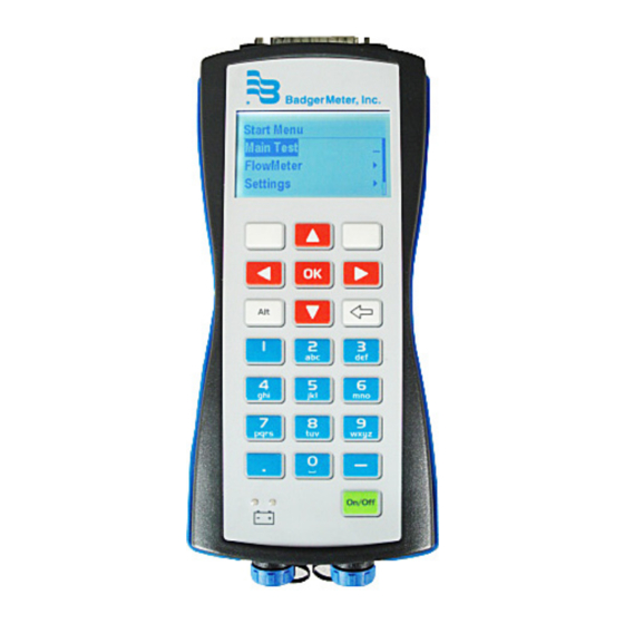
Page 12: Display And Keypad
Display and Keypad DISPLAY AND KEYPAD Display The display is a backlit LCD that displays the current date and time, percent of battery charge and menu indications Keypad The keypad consists of 9 function keys, 12 numeric keys and the On/Off key D-25 Harness Connector Display Left Select... -
Page 13: Menu Structure
Menu Structure MENU STRUCTURE Refer to the following chart when navigating the Field Verification Device menus August 2021 MAG-UM-00368-EN-03 Page 13... -
Page 14: Field Verification Device Settings
Field Verification Device Settings FIELD VERIFICATION DEVICE SETTINGS Press On/Off on the Field Verification Device and wait for the SelfTest to complete This takes a few seconds After the SelfTest, the display shows date, time, battery capacity and firmware version Check to make sure the date and time are correct because the test reports are stored and printed with this data When the Start Menu appears, press Left Select Language... -
Page 15: Time
Field Verification Device Settings Time 1 Select StartMenu > Settings > Misc > Time 2 Edit the hour and minutes in the edit box by using the numeric keypad Use ► to move the cursor 3 Press Right Select to confirm the new time Contrast Adjust the contrast of the display using ◄... -
Page 16: Field Verification Device Tests
Field Verification Device Tests FIELD VERIFICATION DEVICE TESTS Main Test The main test is the standard process for meter testing The result of this test is automatically stored in the memory of the Field Verification Device and can be uploaded to the PC program Perform the following steps: 1 Switch off the flow meter and connect the specific wire harness to the amplifier circuit board 2 Connect the male D-25 connector of the harness to the corresponding female connector on the Field Verification Device... -
Page 17: Manual Tests
Manual Tests 10 If the test Failed, press Left Select to see the results See the example below MANUAL TESTS The result of the manual tests are not stored in the memory of the Field Verification Device and cannot be uploaded to the PC program 1 Switch off the flow meter and connect the specific wire harness to the amplifier circuit board 2 Connect the male D-25 connector of the harness to the corresponding female connector on the Field Verification Device... -
Page 18: Main Test Fails
Manual Tests • Electrode impedance—Measures the impedance of the 3 electrodes (measuring and empty pipe) in [Ohm] • Isolation—Measures the resistance of the coils against ground [Ohm] Main Test Fails Shows the test result of the last Main Test Meter Identification The menu displays information about the connected flow meter •... -
Page 19: Pc Software
Field Verification Device shows USB Mass Storage 3 The following PC window will be opened automatically Select the Badger Meter Verification Device and click OK If the window will not open click FILE and OPEN (Ctrl+O) in the upper task bar... - Page 20 PC Software The downloaded measurements are displayed on the left side of the window 5 Select the new measurements and enter the following information for each test Customer tag is already given by entering the Test ID during the testing with the Field Verification Device Click Save changes to save the entries Page 20 MAG-UM-00368-EN-03 August 2021...
-
Page 21: Print Reports
PC Software Print Reports 1 Select the measurement you want to print 2 Click File and Print A preview window is shown: 3 Click the printer symbol August 2021 MAG-UM-00368-EN-03 Page 21... -
Page 22: Export Reports
PC Software Export Reports 1 Select Export all... for all or Export selected for exporting one measurement 2 Save the data in “CSV” format to be imported to MS Excel® Language Selection 1 Select Tools and Options 2 The Options menu opens Select a Language (The default is English ) Page 22 MAG-UM-00368-EN-03 August 2021... -
Page 23: Specifications
Specifications SPECIFICATIONS Dimensions 8 3 × 4 × 1 5 inches (210 × 102 × 39 millimeters) Weight 15 9 ounces (450 grams) One female D-25 Cannon connector for the meter harness communications port Connectors One USB 2 0 computer connection or 12V DC charging One +5V AC, 3 0A power connection for battery recharging Backlit LCD Display... - Page 24 Control. Manage. Optimize. ModMAG is registered trademark of Badger Meter, Inc Other trademarks appearing in this document are the property of their respective entities Due to continuous research, product improvements and enhancements, Badger Meter reserves the right to change product or system specifications without notice, except to the extent an outstanding contractual obligation exists ©...
Need help?
Do you have a question about the ModMAG M1000 and is the answer not in the manual?
Questions and answers