Badger Meter ModMAG M1000 Installation And Operation Manual
Hide thumbs
Also See for ModMAG M1000:
- Installation and operation manual (85 pages) ,
- User manual (26 pages) ,
- User manual (24 pages)

Related Manuals for Badger Meter ModMAG M1000


Summary of Contents for Badger Meter ModMAG M1000
- Page 1 Badger Meter Europa GmbH ® ModMAG M1000 ® INSTALLATION AND OPERATION MANUAL February 2018 MID_M1000_BA_02_1802...
-
Page 2: Table Of Contents
Contents Page 1. Basic safety precautions ....................1 2. System description ......................2 3. Installation ........................4 General information ....................4 3.1.1 Temperature ranges ..................4 3.1.2 Protection class ..................... 4 3.1.3 Transport ....................... 5 Installation ....................... 5 3.2.1 Meter orientation ................... 5 3.2.2 Inlet and outlet pipe .................. -
Page 3: Basic Safety Precautions
Basic safety precautions Page 1/47 1. Basic safety precautions Before installing or using this product, please read this instruction manual thoroughly. Only qualified personnel should install and/or repair this product. If a fault appears, contact your distributor. Installation Do not place any unit on an unstable surface that may allow it to fall. Never place the units above a radiator or heating unit. -
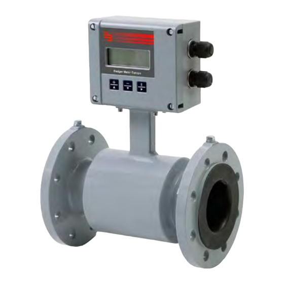
Page 4: System Description
System description Page 2/47 2. System description The electromagnetic flow meters are intended for the metering of all fluids with electric conductivity of at least 5 µS/cm (20 µS/cm for demineralized water). These series of meters is characterized by a high degree of accuracy. Measuring results are independent of density, temperature and pressure. - Page 5 Installation Page 3/47 Nameplate Look at the device nameplate to ensure that the device is delivered according to your order. Check for the correct supply voltage printed on the nameplate. MID_M1000_BA_02_1802...
-
Page 6: Installation
Installation Page 4/47 3. Installation • Warning: Installation instructions given in the following are to be observed in order to guarantee a perfect functioning and a safe operation of the meter. 3.1 General information 3.1.1 Temperature ranges • Caution: In order to prevent a damaging of the meter, you are requested to strictly observe amplifier’s and detector’s maximum temperature ranges. -
Page 7: Transport
Installation Page 5/47 3.1.3 Transport Caution: • Use lifting lugs when lifting meter flow tubes that are 150 in diameter or larger. • Do not lift meter on measuring amplifier or on detector’s neck. • Do not lift meter with a fork lift on the jacket sheet. This could damage the body. -
Page 8: Meter Location
Installation Page 6/47 3.2.3 Meter location Caution: • Do not install the detector on the suction sides of pumps. This could damage the liner (in particular PTFE liners). • Verify that the pipeline is always filled on the measuring point, if not - a correct or accurate measurement is not possible. -
Page 9: Pipe Reducer Requirements
Installation Page 7/47 3.2.4 Pipe reducer requirements With pipe reducers as per DIN 28545 detectors can be mounted in larger pipelines. You can determine the occurring pressure drop by using the shown nomogram (only applicable to liquids with similar viscosity like water). •... -
Page 10: Separate Version
Installation Page 8/47 3.2.5 Separate version Provide a separate version in the following cases: • Note: Detector protection class IP 68 • Medium temperature > 100 °C • Strong vibrations Caution: • Do not install the signal cable close to power cables, electric machines, etc. -
Page 11: Plastic Or Lined Pipelines
Installation Page 9/47 "X" M4:1 "X" 3.2.7 Plastic or lined pipelines If non-conductive pipelines or pipelines lined with non-conductive material are used, install an additional grounding electrode or grounding rings between the flanges. Grounding rings are installed like gaskets between the flanges and are connected with a grounding cable to the meter. -
Page 12: Electrically Disturbed Environment
Installation Page 10/47 3.2.9 Electrically disturbed environment If the pipe material is in an electrically disturbed environment or if metallic pipelines that are not grounded are used, we recommend a groundring as shown in the following picture in order to assure that measurement is not influenced. 6 mm²... -
Page 13: Power Connections
Power connections Page 11/47 4. Power connections • Caution: For the 2 x M20 cable inlets only use flexible electric cables. • Use separate cable inlets for auxiliary power, signal and input/output cables. 4.1 Auxiliary power • Warning: Do not connect meter under impressed mains voltage. •... -
Page 14: Separate Version
Close device and connection cover again From To Amplifier Detector firmly. 13 SHIELD Shield 13 12 COIL COIL 12 11 COIL COIL 11 Badger Meter JBOX - PRIMO REMOTE - REV1 Terminal box – Terminal M1000 Description Wire color Standard Stainless steel Coil 1 Green... -
Page 15: Signal Cable Specification
Page 13/47 4.2.1 Signal cable specification • Note: Only use signal cables delivered by Badger Meter or corresponding cable in accordance with the following specification. • Take max. signal cable length between detector and amplifier into account (keep distance as low as possible). -
Page 16: Configuring Input/Output (I/O)
Power connections Page 14/47 4.3 Configuring input/output (I/O) Auxiliary power Solid State Relay Ethernet Display (in process) Dig. Out- and Input Analog Output RS-Interface Electrodes RS-Interface Coil detector detector DIP switch Input/Output Description Terminal 0 - 20 mA Analog output* 7 (+) 4 - 20 mA RL <... -
Page 17: In- And Output Cable Connection
Power connections Page 15/47 4.3.1 In- and output cable connection For the normal I/Os use shielded cables. Connect the shield of the cable to one of the grounding screw. Recommended cable LiYCY size min. 0,14 mm². Solid State Output In case the second cable gland is used for the normal I/Os, use one cable and cable gland for the power supply and Solid Satate relay. -
Page 18: Programming
Programming Page 16/47 5. Programming Programming is accomplished by using the three functional buttons ▲, ► and Exit/Save. You can move from the measuring mode to the programming mode by pressing once the button Exit/Save. menu header Main Menu submenu Meter Setup scrollbar indication of a submenu... -
Page 19: Main Menu
Programming Page 17/47 5.1 Main menu The following menu items are available to you in the main menu: • Meter setup • Measurements • Inputs and outputs • Totalizer reset • Communication • Miscellaneous Information • • 5.1.1 Meter setup This figure is used for setting pipe’s diameter Calibration Diameter... - Page 20 Programming Page 18/47 Power Line For an optimum operation of the meter, set Power Line Frequency Frequency 50 Hz or 60 Hz in this menu at operating location. Excitation This value shows in which frequency the meter’s coils are operated. Frequency Supported frequencies are dependent on the configured power line frequency and meter’s size.
-
Page 21: Measurement
Programming Page 19/47 5.1.2 Measurement Flow Units let you select among the Flow Units mentioned below. Flow Unit Flow units are automatically converted into the selected unit. Unit Unit Liter/Second gal/s Gallons/Sec. L/min Liter/Minute g/min Gallons/Min. Liter/Hour Gallons/Hour m³/s Cubic MG/D MegaGallon/Day m³/min... - Page 22 Programming Page 20/47 Full Scale Flow This parameter sets the maximum flow the system is expected to measure. This parameter has influence on other system parameters like analog output or low flow cut-off. In terms of flow velocity, the meter’s limit are from 0.1 to 12 m/sec. The full scale flow is valid for both flow directions.
- Page 23 Programming Page 21/47 Moving Average Moving average filter (MAV) smooth out short- term fluctuations. The value can be adjusted from 1 to 200 measuring periods. The delay is calculated: Delay [s] = ( MAV – 1) x T The time T is given by the adjusted excitation frequency of the meter (see also chapter 5.2.1) Excitation T = Time for filter...
-
Page 24: Input And Outputs
Programming Page 22/47 5.1.3 Input and outputs Analog output Range This parameter establishes the range of the analog output signal: 0 to 100% (= full scale). The following cur- rent ranges are available to you: Current output 0 to 20 mA 4 to 20 mA 0 to 10 mA Analog output active... - Page 25 Programming Page 23/47 Digital input lets you reset totalizers (Remote reset), or Digital Input interrupt flow measurement (PosZeroReturn). If the function of the digital output 1 or 2 is selected as preselection meter, the function of the digital output is automatically set to “Preselection Meter Reset”.
- Page 26 Programming Page 24/47 Digital Outputs You can configure functional operation of the 2 digital outputs. You can select e.g “forward pulse” for the digital output and define the pulses per totalizer unit via “pulse scale”. Digital outputs 1 and 2 The two outputs can be operated as open collector passively or actively.
- Page 27 Programming Page 25/47 Digital Outputs Functional The following functions can be selected for the selection Outputs 1 to 2 as well as for the Solid State Relay. The Solid State Relay function is linked with the func- tion of output 2. Function Out1 Out2 / Solid...
- Page 28 Programming Page 26/47 Pulse Width This parameter establishes the “On” duration of the transmitted pulse. The configurable range ist from 0 msec to 2000 ms. If 0 ms is configured, pulse width is automatically adapted depending on pulse frequency (pulse/pause ratio 1:1). During the configuration the program checks if pulses/unit and pulse width are in accordance with full scale defined, if not an error alarm is displayed.
-
Page 29: Clear Totals
Programming Page 27/47 5.1.4 Clear totals The unidirectional totalizer T2 is reset within the menu manager. 5.1.5 Communications Interfaces ModBus ® RS232, RS485 and RS422 with ModBus ® RTU. Mode can be configured by DIP switches also if Termination ON or OFF. M-Bus Optional and needs additional hardware board HART... - Page 30 Programming Page 28/47 Ethernet ModBus TCP/IP with MEAP-Header ® IP Address IPv4-Address IP Mask IPv4 subnetting reference IP Gateway Gateway address Media-Access-Control-Address Address Control On or Off Protocol 1 or 2 Dial 4 to 9 Resolution 0,001 / 0,01 / 0,1 / 1 / 10 / 100 / 1.000 / 10.000 MID_M1000_BA_02_1802...
-
Page 31: Miscellaneous
Programming Page 29/47 5.1.6 Miscellaneous Off, On and Preset Power up The number of times that the unit has been powered on. Settling time Measures settling of coils and must be less than one quarter of excitation period. 0 ms in case no detector is connected. Language The unit supports different languages as : •... -
Page 32: Info
Programming Page 30/47 Datalog Period The data logging period can be adjusted as following: every 15 min / 1 h / 6 h / 12 h / 24 h There is a 500 kB memory with about 30.000 data records for data logging available. -
Page 33: Pin
Programming Page 31/47 5.1.8 Pin The different menus and parameterings can be secured via three password levels. • Administrator PIN • Service PIN User PIN • The password protection is a 6-digit PIN which is parametered on [000000] and deactivated at the factory. -
Page 34: Troubleshooting
Troubleshooting Page 32/47 6. Troubleshooting The following error messages can be displayed: Description Possible cause Recommended action Coil Meter not connected. Check if meter is connected and Disconnected make sure that cable connection is Connection to meter interrupted. not interrupted. - Page 35 Troubleshooting Page 33/47 Inaccurate Wrong parameters. Check parameters (detector, measurement amplifier and size) as per annexed data sheet Pipe not completely full. Check if measuring pipe completely full. MID_M1000_BA_02_1802...
-
Page 36: Control Led
Troubleshooting Page 34/47 6.1 Control LED On the board there are several LED to control the operation of the device. See below the LEDs and the meaning Main Board LED1 LED3 LED2 LED10 LED7 LED6 LED8 Display Board LED13 LED5 LED1 Coil loop (On = active / Off loop open) LED2... -
Page 37: Replace Meter's Electronics
Troubleshooting Page 35/47 6.2 Replace meter’s electronics • Warning: Disconnect auxiliary power before opening body cover. Electrode plug at the display board Coil plug Pull out all plugs. Loosen screws S1-S4 and take out circuit board. Insert new circuit board and fix it by fastening the screws S1-S4. Plug again all plugs. If necessary, configure new circuit board related to the available meter (detector, size). -
Page 38: Technical Data
Technical data Page 36/47 7. Technical data 7.1 Detector Type II Technical data Size DN 6 – DN 500 (1/4“ to 20“) Process connections Flange: DIN, ANSI, JIS, AWWA etc. Nominal pressure Up to PN 100 (PED) Protection class IP 67, IP 68 optional Min. - Page 39 Technical data Page 37/47 ANSI flanges DIN flanges A Std* ∅ D ∅ K ∅ d2xn ∅ D ∅ K ∅ d2xn ISO** 1/4” 88,9 60,3 15,9 x 4 14 x 4 3/10” 88,9 60,3 15,9 x 4 14 x 4 3/8”...
-
Page 40: Detector Type Food
Technical data Page 38/47 7.2 Detector type Food Technical data Size DN 10 – DN 100 (3/8“ to 4“) Process connections Tri-Clamp ® , DIN 11851, ISO 2852, etc. Nominal pressure PN 10 Protective class IP 65, IP 68 optional Min. - Page 41 Technical data Page 39/47 Process connection Tri-Clamp ® Process connection DIN 11851 ModMAG ® M1000 mounted version ModMAG ® M1000 mounted version (in mm) (in mm) 70,5 70,5 Type Food Tri-Clamp ® Type Food Milk Pipe DIN 11851 3/8” 3/8” 1/2”...
-
Page 42: Detector Type Iii
Technical data Page 40/47 7.3 Detector Type III Technical Data Size DN 25 – DN 100 (1“ to 4“) Process connections Sandwich connection, (intermediate flange mounting) Nominal pressure PN 40 Protective class IP 67, IP 68 optional Min. conductivity 5 µS/cm (20 µS/cm demineralized water) Liner PTFE -40 °C to +150 °C... -
Page 43: Meter Type Modmag ® M1000
Technical data Page 41/47 7.4 Meter type ModMAG M1000 ® Technical data Type ModMAG ® M1000 Auxiliary power 92-275 VAC (50 / 60 Hz), 13 VA optional 9-36 VDC, 4 W Analog output 0/4 – 20 mA, ≤ 800 Ohm Flow direction is displayed via separate status output Digital outputs 2 open collectors, passive 32 VDC, 0-100 Hz 100 mA, 100-... -
Page 44: Error Limits
Technical data Page 42/47 7.5 Error limits Measuring range 0,03 m/s to 12 m/s Pulse output ±0,3% of m.v. ± 2 mm/s Analog output Similar to pulse output plus ±0,01 mA Reproducibility ±0,1% Reference conditions: Ambient and fluid temperature 20 °C Electr. -
Page 45: Size Select
Technical data Page 43/47 7.6 Size select DN 6 - DN 100 0,01 0,01 1.000 10.000 L/min DN 125 - DN 200 0,01 1000 10.000 100.0 m³/h MID_M1000_BA_02_1802... -
Page 46: Program Structure
Program structure Page 44/47 8. Program structure MID_M1000_BA_02_1802... - Page 47 Program structure Page 45/47 MID_M1000_BA_02_1802...
-
Page 48: Spare Parts
Spare parts Page 46/47 9. Spare parts Pos. Description Part n° 92-275 VAC Amplifier assembly complete 592410 9-36 VDC Amplifier assembly complete 592412 92-275 VAC Board 384528 9-36 VDC Board 384529 92-275 VAC Board with Ethernet 384585 9-36 VDC Board with Ethernet 384586 Housing 384525... -
Page 49: Return Of Goods For Repair
Return of goods for repair Page 47/47 10. Return of goods for repair Please refer to our claims return form / harmlessness declaration under: http://www.badgermeter.de/en/service/return-of-goods.html MID_M1000_BA_02_1802... - Page 52 Hotline Phone +49-7025-9208-0 or -30 +49-7025-9208-15 Badger Meter Europa GmbH ® Subsidiary of Badger Meter, Inc., USA Nürtinger Strasse 76 72639 Neuffen (Germany) E-mail: badger@badgermeter.de www.badgermeter.de...
Need help?
Do you have a question about the ModMAG M1000 and is the answer not in the manual?
Questions and answers