
Subscribe to Our Youtube Channel
Related Manuals for Badger Meter ModMAG M-Series M7600


Summary of Contents for Badger Meter ModMAG M-Series M7600
- Page 1 M-Series® M7600 Electromagnetic Flow Meter User Manual MAG-UM-00507-EN-02 (February 2018)
- Page 2 M-Series® M7600 Electromagnetic Flow Meter Page ii MAG-UM-00507-EN-02 February 2018...
-
Page 3: Table Of Contents
User Manual CONTENTS Scope of This Manual Safety Precautions and Instructions System Description Unpacking and Inspection Rigging, Lifting and Moving Large Units Meter Location, Orientation and Applications Meter Mount Configuration Temperature Ranges Pipelines and Fluid Flow Meter Orientation Straight Pipe Requirements Pipe Reducer Requirements Chemical Injection Applications Partially-Filled Pipe Situations... - Page 4 M-Series® M7600 Electromagnetic Flow Meter Specifications Performance Materials of Construction Inputs Outputs Approvals Page iv MAG-UM-00507-EN-02 February 2018...
-
Page 5: Scope Of This Manual
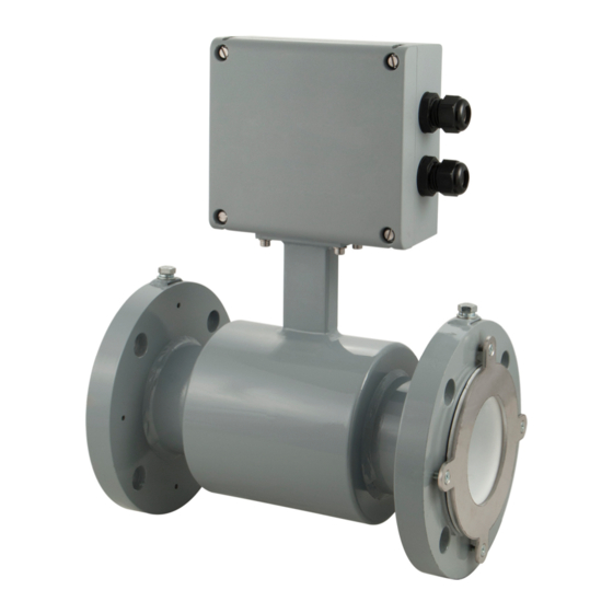
SYSTEM DESCRIPTION The Badger Meter M7600 electromagnetic flow meter successfully combines the most advanced electromagnetic flow metering technology with the simplicity and ruggedness of the Badger Meter proven Batching Systems for Industrial Applications The M7600 meter is intended for fluid metering in most industries including water, wastewater, food and beverage,... -
Page 6: Unpacking And Inspection
If the unit was damaged in transit, it is your responsibility to request an inspection report from the carrier within 48 hours You must then file a claim with the carrier and contact Badger Meter for appropriate repairs or replacement •... -
Page 7: Meter Location, Orientation And Applications
Meter Location, Orientation and Applications METER LOCATION, ORIENTATION AND APPLICATIONS Meter Mount Configuration The meter mount configuration has the amplifier mounted directly on the detector This compact, self-contained configuration minimizes installation wiring Temperature Ranges TO PREVENT DAMAGE TO THE METER, STRICTLY OBSERVE THE AMPLIFIER’S AND DETECTOR’S MAXIMUM TEMPERATURE RANGES. -
Page 8: Meter Orientation
Meter Location, Orientation and Applications Meter Orientation Mag meters can operate accurately in any pipeline orientation and can measure volumetric flow in forward and reverse directions OTEE: A "Forward Flow" direction arrow is printed on the detector label Vertical Placement Mag meters perform best when placed vertically, with liquid flowing upward and meter electrodes in a closed, full pipe Vertical placement allows the pipe to remain completely full, even in low flow, low pressure applications, and it prevents solids build-up, sediment deposit and accumulation on the liner and electrodes... -
Page 9: Pipe Reducer Requirements
Meter Location, Orientation and Applications Pipe Reducer Requirements With pipe reducers, a smaller meter can be mounted in larger pipelines This arrangement may increase low-flow accuracy There are no special requirements for standard, concentric, pipe reducers Custom fabricated pipe reducers must have an approximate slope angle of 15 degrees to minimize flow disturbances and excessive loss of head If this is not possible, install the custom pipe reducers as if they were fittings and install the required amount of straight pipe Figure 8: Pipe reducer requirements... -
Page 10: Partially-Filled Pipe Situations
Meter Location, Orientation and Applications Partially-Filled Pipe Situations In some locations, the process pipe may be momentarily only partially filled Examples include: lack of back pressure, insufficient line pressure and gravity flow applications To eliminate these situations: • Do not install the meter at the highest point of the pipeline •... -
Page 11: Meter Gaskets And Grounding
Meter Gaskets and Grounding METER GASKETS AND GROUNDING Gasket and grounding requirements must be considered when determining the meter location, orientation and application Grounding rings are provided with the M7600 meter Meter/Pipeline Connection Gaskets You must install gaskets (provided) between the detector's isolating liner and the pipeline flange to ensure a proper and secure hydraulic seal Use gaskets that are compatible with the fluid Center each gasket on the flange to avoid flow restrictions or turbulence in the line During installation, do not use graphite or any electrically conductive sealing compound to hold the gaskets This could... -
Page 12: Power Connections
Power Connections POWER CONNECTIONS Wiring Safety AT INSTALLATION, BE SURE TO COMPLY WITH THE FOLLOWING REQUIREMENTS: • Disconnect power to the unit before attempting any connection or service to the unit • Do not bundle or route signal lines with power lines •... -
Page 13: Power Supply Connections
Power Connections Power Supply Connections External Disconnect • Install an external disconnect switch or circuit breaker that meets local standards • Position the M7600 meter in an accessible location • Position and identify the disconnect device so as to provide safe and easy operation •... -
Page 14: Configuring Input/Output (I/O)
Power Connections Configuring Input/Output (I/O) Power supply Pulse output, solid-state relays (S1, S2) Display Pulse output, open collector (1, 2) Alarm output (3, 4) Exit Push-buttons Save Coil connector Figure 18: Configuring I/O Output Description Terminal Open collector max 10 kHz 1 and 2 Passive max 32V DC, <100 Hz 100 mA, >100 Hz 20 mA Pulse Output... -
Page 15: Wiring To A Pc-200 Controller
Power Connections Wiring to a PC-200 Controller To connect the open collector scaled pulse output from the Model M7600 meter to the PC-200 controller, follow Figure 20 Common Open Collector Transistor Output DC-Switched Figure 20: Wiring to a PC-200 controller Wiring to an ER-10 Industrial Register Common Open Collector... -
Page 16: Menu Programming Options
Menu Programming Options MENU PROGRAMMING OPTIONS Screen Layout The following M7600 meter programming options are available from the M7600 Menu: • Scale factor • Pulse/unit • Flow unit • Totalizer unit Function Buttons All M7600 programming is accomplished using the three function buttons located on the front of the amplifier Screen navigation, digit, and parameter selection is performed by pressing a combination of these three buttons Display Exit... -
Page 17: M7600 Menu
Menu Programming Options M7600 Menu Scale Factor Changing the scale factor lets you adjust the meter’s accuracy without disturbing parameters set by the factory You can tune the meter to meet changing application requirements in a range of ± 10% (0 90 to 1 10) If it is necessary to recalibrate the meter, follow these steps: 1 Determine the exact quantity of fluid that actually passed through the meter by using a calibrated volumetric container or by weighing the container... -
Page 18: Maintenance
Maintenance MAINTENANCE Mandatory, routine or scheduled maintenance should not be required for the M7600 Mag Meter electronics or flow tube after proper installation However, some occurrences may require personnel to perform the following: • Flow tube and electrode cleaning • Circuit board replacement DO NOT CLEAN COMPONENTS INSIDE THE AMPLIFIER OR JUNCTION BOX. -
Page 19: Troubleshooting
TROUBLESHOOTING The M7600 mag meter is designed for many years of optimal performance However, should it malfunction, there are certain things that we recommend you check before contacting our Technical Support department or your local Badger Meter Representative Errors & Warnings... - Page 20 The Americas | Badger Meter | 4545 West Brown Deer Rd | PO Box 245036 | Milwaukee, WI 53224-9536 | 800-876-3837 | 414-355-0400 México | Badger Meter de las Americas, S.A. de C.V. | Pedro Luis Ogazón N°32 | Esq. Angelina N°24 | Colonia Guadalupe Inn | CP 01050 | México, DF | México | +52-55-5662-0882 Europe, Eastern Europe Branch Office (for Poland, Latvia, Lithuania, Estonia, Ukraine, Belarus) | Badger Meter Europe | ul.
Need help?
Do you have a question about the ModMAG M-Series M7600 and is the answer not in the manual?
Questions and answers