Table of Contents
Advertisement
Quick Links
Advertisement
Table of Contents

Related Manuals for Badger Meter ModMAG M Series


Summary of Contents for Badger Meter ModMAG M Series
- Page 1 Electromagnetic Flow Meter M2000 User Manual MAG-UM-01272-EN-21 (March 2022)
- Page 2 Electromagnetic Flow Meter M2000 Page ii MAG-UM-01272-EN-21 March 2022...
-
Page 3: Table Of Contents
User Manual CONTENTS Safety Precautions and Instructions . . . . . . . . . . . . . . . . . . . . . . . . . . . . . . . . . . . . . . . . . . . . . . . . . . . . . . . . . . . 5 Basic Safety Precautions . - Page 4 Electromagnetic Flow Meter M2000 Programming the M2000 Meter . . . . . . . . . . . . . . . . . . . . . . . . . . . . . . . . . . . . . . . . . . . . . . . . . . . . . . . . . . . . 27 Function Buttons .
-
Page 5: Safety Precautions And Instructions
Safety Precautions and Instructions SAFETY PRECAUTIONS AND INSTRUCTIONS Some procedures in this manual require special safety considerations . In such cases, the text is emphasized with the following symbols: Indicates a hazardous situation, which, if not avoided, will result in death or serious personal injury . WARNING Indicates a hazardous situation, which, if not avoided, could result in death or serious personal injury . -
Page 6: System Description
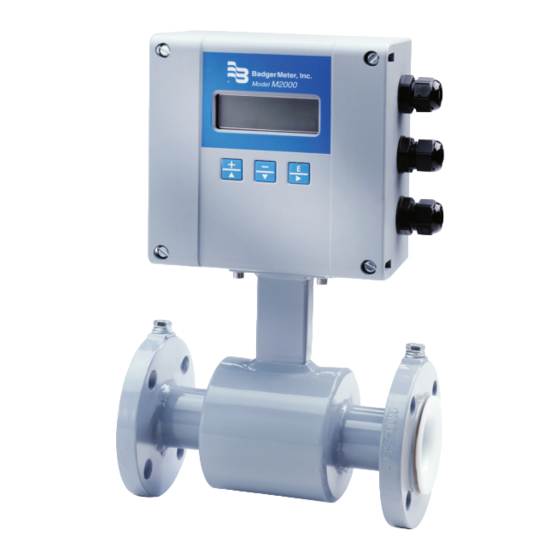
System Description SYSTEM DESCRIPTION The Badger Meter model M2000 electromagnetic flow meter is intended for fluid metering in most industries including water, wastewater, food and beverage, pharmaceutical and chemical . The meter is intended for the metering of all fluids with electric conductivity of at least 5 µS/cm (20 µS/cm for demineralized water) . -
Page 7: Unpacking And Inspection
Unpacking and Inspection UNPACKING AND INSPECTION Follow these guidelines when unpacking the equipment . • If a shipping container shows any sign of damage, have the shipper present when you unpack the meter . • Follow all unpacking, lifting and moving instructions associated with the shipping container . •... - Page 8 Unpacking and Inspection • Use the sling-rigged method to lift large sensors into a vertical position while they are still crated . Use this method to position large sensors vertically into pipelines . Figure 3: Sling-Rigged lifting methods • Do not lift a sensor with a forklift by positioning the sensor body on the forks, with the flanges extending beyond the lift . This could dent the housing or damage the internal coil assemblies .
-
Page 9: Meter Location, Orientation And Applications
Meter Location, Orientation and Applications METER LOCATION, ORIENTATION AND APPLICATIONS Gasket and grounding requirements must be considered when determining the meter location, orientation and application . “Meter Gaskets and Grounding” on page 15 . There are two transmitter mounting options: a meter mount option and a remote mount option . -
Page 10: Temperature Ranges
Meter Location, Orientation and Applications The National Electronics Manufacturer's Association (NEMA) 6P enclosures are constructed for indoor or outdoor use . The 6P enclosures provide protection against access to hazardous parts . They also provide a degree of protection against ingress of solid foreign objects and water (hose directed water and the entry of water during prolonged submersion at a limited depth) which provide an additional level of protection against corrosion and that are not damaged by the external formation of ice on the enclosure . -
Page 11: Meter Orientation
Meter Location, Orientation and Applications • For sensors with PTFE liner, only remove the protective cap on the flange or on the threaded pipes of milk pipe screws per DIN 11851 shortly before installation . Meter Orientation Mag meters can operate accurately in any pipeline orientation and can measure volumetric flow in forward and reverse directions as long as the pipe is completely full . -
Page 12: Pipe Reducer Requirements
Meter Location, Orientation and Applications Flow Meter D (Pipe Size) D (Pipe Size) Forward Flow Elbow 3 x D 2 x D Gate Valve (Fully Open) Minimum Straight Pipe Minimum Straight Pipe Check Valve Globe Valve Elbow 7 x D Standard Concentric Butter y Valve Reducers... -
Page 13: Chemical Injection Applications
Meter Location, Orientation and Applications Chemical Injection Applications For water line applications with a chemical injection point, install the meter upstream of the injection point . This eliminates any meter performance issues . Chemical Injection Flow Meter Here Forward Flow Upstream Downstream Figure 10: Chemical injection point downstream of meter... -
Page 14: Partially-Filled Pipe Situations
Meter Location, Orientation and Applications Partially-Filled Pipe Situations In some locations, the process pipe may be momentarily only partially filled . Examples include: lack of back pressure, insufficient line pressure and gravity flow applications . To eliminate these situations: • Do not install the meter at the highest point of the pipeline . -
Page 15: Meter Gaskets And Grounding
Meter Gaskets and Grounding METER GASKETS AND GROUNDING Gaskets and grounding are required for proper meter installation . IMPORTANT If you received grounding rings with your meter, install them. Electromagnetic meters require a good ground for proper operation. Grounding rings also help protect the edge of the liner from debris that may flow from the pipe. Meter/Pipeline Connection Gaskets IMPORTANT It is essential that the transmitter’s input ground (zero voltage reference) be electrically connected to the liquid media and to a good,... -
Page 16: Recommended Installation With Grounding Rings
Meter Gaskets and Grounding "X" M4:1 "X" Figure 16: Grounding electrode Recommended Installation with Grounding Rings IMPORTANT Badger Meter recommends the installation of a pair of grounding rings between the mating flanges at both ends of the meter. See Figure 15 on page Connect the grounding straps to both of the grounding rings and to a good, solid earth ground . -
Page 17: Plastic Or Lined Pipelines
Meter Gaskets and Grounding Plastic or Lined Pipelines If non-conductive pipelines or pipelines lined with non-conductive material are used, install an additional grounding electrode or grounding rings between the flanges . Grounding rings are installed like gaskets between the flanges and are connected with a grounding cable to the meter (See Figure 15 on page 15) . -
Page 18: Wiring
Wiring WIRING Wiring Safety AT INSTALLATION, BE SURE TO COMPLY WITH THE FOLLOWING REQUIREMENTS: • Disconnect power to the unit before attempting any connection or service to the unit. Do not bundle or route signal lines with power lines. • •... -
Page 19: Remote Mount Installation
Wiring External Disconnect INSTALL AN EXTERNAL DISCONNECT SWITCH OR CIRCUIT BREAKER THAT MEETS LOCAL STANDARDS. POSITION THE M2000 METER IN AN ACCESSIBLE LOCATION. POSITION AND IDENTIFY THE DISCONNECT DEVICE SO AS TO PROVIDE SAFE AND EASY OPERATION. LABEL THE DISCONNECT DEVICE AS BEING FOR THE MAG METER. AC Power Wiring For the AC power connections, use a three-wire sheathed connection cable suitable for the rating of this device . - Page 20 Wiring Wiring for Remote Configuration CONNECT OR SEPARATE SIGNAL CONNECTION CABLE ONLY WHEN THE UNIT HAS BEEN SWITCHED OFF. M2000 Ampli er CS C2 C1 Shield (cut o ) 11 Coil Green (11) 12 Coil Yellow (12) 13 Shield Black (13) Overall Shield 45 Electrode White (45) Electrode 44 Shield...
-
Page 21: Signal Cable Specification
Wiring Signal Cable Specification OTE: Only use signal cables delivered by Badger Meter or corresponding cable in accordance with the following specification . Take maximum signal cable length between sensor and transmitter into account (keep distance as low as possible) . Distance With electrode idle Loop resistance 0…75 m... -
Page 22: Configuring Input/Output (I/O)
Configuring Input/Output (I/O) CONFIGURING INPUT/OUTPUT (I/O) This section describes wiring the following M2000 meter inputs/outputs: • Analog output • Digital input • Digital outputs • Communication Once the sensor and the transmitter have been wired, wire any inputs and outputs to the M2000 transmitter . Do not connect the main power connection until you have made all other wiring connections . -
Page 23: Analog Output Wiring Diagram
Configuring Input/Output (I/O) Input/Output Description Terminal Analog Output 0…20 mA Resistive Load < 800 ohms 16 (+) 4…20 mA Resistive Load < 800 ohms 15 (–) 0…10 mA Resistive Load < 800 ohms 2…10 mA Resistive Load < 800 ohms Digital Output 1 Passive maximum 30V DC, 100 mA 1 (+) and 2 (–) -
Page 24: Digital Output Wiring Diagrams
Configuring Input/Output (I/O) Digital Output Wiring Diagrams Figure 23: Digital output wiring diagrams Page 24 MAG-UM-01272-EN-21 March 2022... -
Page 25: Digital Input Wiring Diagram
Configuring Input/Output (I/O) Digital Input Wiring Diagram Figure 24: Digital input wiring diagram OTE: Option 2 can be connected to terminals 1 and 8 or optionally to terminals 3 and 8 . Depending on which output is used, set this output to 24V supply . Communication Interfaces M2000 offers following communication interfaces: •... - Page 26 Configuring Input/Output (I/O) DISPLAY COMMUNICATION Communication Interface Figure 25: Communication interface The internal communications between the main board and the interface board are done via Port B . For M-Bus, HART and Profibus DP, the following adjustments are done in the menu Communication->Port B Port B: Port Adr .
-
Page 27: Programming The M2000 Meter
Programming the M2000 Meter PROGRAMMING THE M2000 METER The M2000 transmitter comes pre-programmed from the factory . Typically, you do not need to do any additional programming . However, to take advantage of special features, you can program the meter for your specific needs . If you are programming the meter, familiarize yourself with the Function Buttons and Displays, and follow the procedures outlined in this manual . - Page 28 Programming the M2000 Meter Example 1: Figure 29 shows the Main Menu . The selection arrow points to the Meter Setup selection . Press [↓] once to scroll the text down to the Exit this Menu selection (which is not visible on the display) . Press [↓] MAIN MENU MAIN MENU...
-
Page 29: Displays
Programming the M2000 Meter Displays There are two types of displays on the M2000 meter: • Menu Selection • Numeric Entry Menu Selection Display Menu selection displays appear in the following format: DISPLAY TITLE START MENU >Menu Selection 1 >Exit this Menu Menu Selection 2 Main Menu DIRECTIONS LINE... -
Page 30: Security
Programming the M2000 Meter Security The M2000 meter security feature gives you the option to restrict access to the meter with a five-digit Personal Identification Number (PIN) . The system administrator can set up a single PIN for each of the three levels of access: Administration –... - Page 31 Programming the M2000 Meter Entering Your Personal Identification Number (PIN) If your system has been set up with PIN security, you need to enter a PIN to access programming functions . There are three access levels, each with its own unique PIN: User, Service and Administration . Your system administrator can provide you with the appropriate PIN .
-
Page 32: Setting Up The M2000 Meter With Quick Setup
Programming the M2000 Meter Setting Up the M2000 Meter with Quick Setup The M2000 electromagnetic flow meter provides you with a Quick Setup utility that allows you to set or change your Flow Units, Totalizer Units, Full Scale Flow and Low Flow Cutoff settings . To open the Quick Setup menu, select Quick Setup from the Start Menu . - Page 33 Programming the M2000 Meter Quick Setup Full Scale Flow Use Full Scale Flow to set the maximum flow the system is expected to measure . This parameter influences other system parameters, including: • Frequency Output – Full scale frequency is observed at Full Scale Flow •...
-
Page 34: Menu Structure
Programming the M2000 Meter Menu Structure Start Menu Quick Setup Flow Unit Totalizer Unit Full Scale Flow Low Flow Cutoff Main Menu Meter Setup Scale Factor Empty Pipe Detect Power Line Freq Excitation Freq Pipe Diameter Detector Factor Detector Offset Measurements Velocity Unit Flow Unit... - Page 35 Programming the M2000 Meter Start Menu Main Menu Inputs/Outputs Digital Output #3 Full Scale Freq Preset Amount Set Point Min. Set Point Max. Normally Open Output Type Normally Closed Hardware Select Relay Open Collector Select Function None Frequency Output Flow Set Point Empty Pipe Alarm Flow Direction Preset Output...
-
Page 36: Using The Main Menu Programming Options
Using the Main Menu Programming Options USING THE MAIN MENU PROGRAMMING OPTIONS The following programming options are available from the Main Menu: • Meter Setup • Measurements • Inputs/Outputs • Clear Totals • Communications • Advanced • Info/Help • Language Select In the section that follows, the applicable security level for each menu option is indicated as follows: Administrative Service... - Page 37 Using the Main Menu Programming Options Meter Setup Excitation Freq Use Excitation Freq to configure the DC excitation of the coils . Supported frequencies are dependent on the configured power line frequency: [Factory Set] 50 Hz 60 Hz 1 Hz 1 Hz 3 .125 Hz 3 .75 Hz...
- Page 38 Using the Main Menu Programming Options Measurements Velocity Unit Use Velocity Unit to set the velocity to meters/sec or feet/sec . To set Velocity Unit, follow these steps from the Measurements menu: [Region] 1 . Select Velocity Unit . 2 .
- Page 39 Using the Main Menu Programming Options Measurements Full Scale Flow Use Full Scale Flow to set the maximum flow the system is expected to measure . This parameter has influence on other system parameters, which include: [Factory Set] • Frequency Output – Full scale frequency is observed at Full Scale Flow ...
- Page 40 Using the Main Menu Programming Options Measurements Damping Factor Use Damping Factor to establish the stability of the measured flow rate . If back and forth oscillations of the flow rate are observed during normal flow conditions, increase this value incrementally until the [5 s] flow rate stabilizes .
- Page 41 Using the Main Menu Programming Options Inputs/Outputs Digital Input Use Digital Input to configure the functional operation of the digital input . The following functions are supported: [Disabled] • Remote Reset – Clears totalizer T2 (uni-directional) • Batch Reset – Resets batch totalizer PS to preset amount and clears T2 (uni-directional) •...
- Page 42 Using the Main Menu Programming Options Inputs/Outputs Digital Output Full Scale Use Full Scale Frequency to establish the Full Scale Flow output frequency when the (continued) Frequency flow rate equals the configured Full Scale Flow . [1000 Hz] To change the Full Scale Frequency, follow these steps from the Inputs/Outputs main menu: 1 .
- Page 43 Using the Main Menu Programming Options Inputs/Outputs Digital Output Output Type Use Output Type to set the output switch to normally open or normally closed . (continued) If Normally Open is selected, the output switch is open (no current) when the [1: Normally Open] output is inactive and closed (current flows) when the output is active .
- Page 44 Using the Main Menu Programming Options Inputs/Outputs Digital Output Select Function Use Select Function to configure the functional operation of the associated (continued) [1: Forward Pulse] output . The following operations are supported: • Frequency Output – Generates pulses correlated to the absolute value of [2: Reverse Pulse] the flow rate .
- Page 45 Using the Main Menu Programming Options Inputs/Outputs Flow Flow Simulation provides output simulation based on a percentage of the Full Scale Flow . Simulation Simulation does not accumulate the totalizers . The range of simulation includes –100…100% of the Full Scale Flow . The Flow Simulation Parameter lets you set the range of simulation in 10% increments .
- Page 46 Using the Main Menu Programming Options Communication Port A Settings Interface Use Interface to configure how the RS232 communication port is used . [Modbus RTU] • Modbus RTU • Remote menu (RDI – Remote Display Interface) • Primo 3 .x •...
- Page 47 Using the Main Menu Programming Options Communication Port A Data Bits The following data bits are supported: Settings [8 bits] • 8 bits (continued) • 7 bits • 5 bits To change the data bits, follow these steps from the Port A Settings menu: 1 .
- Page 48 Using the Main Menu Programming Options Communication Port counters are used for diagnostics when configured for Modbus RTU . These counters Port A Diagnostics are only cleared on power up . Counters Counter Description Pkts Processed Number of packets processed by meter . Broadcast Pkts Number of broadcast packets (address = 0) processed by meter .
- Page 49 Using the Main Menu Programming Options Advanced Encoder Protocol Protocol Type The Protocol Type enables the encoder interface . Selecting V1 or V2 automatically configures the Digital Input and Digital Output #1 for encoder operation . Manually configuring the input and output for encoder operation is not allowed and results in an error .
- Page 50 Using the Main Menu Programming Options Advanced Analog Calibrate Custom Settings To set the analog calibration custom settings, follow these steps from the [Zero Scale: 0 mA] Advanced menu: 1 . Select Analog Calibrate to view the Analog Calibrate menu . [Full Scale: 0 mA] 2 .
- Page 51 Using the Main Menu Programming Options Advanced Software Filter Description This software filter operates as an acceleration filter . This filter, when configured ACC-Filter properly, allows for filtering of fast changes in fluid flow . Generally, this filter is used in applications having highly conductive fluids . It is intended to help provide smoothing of the analog output and display fluctuations .
- Page 52 Using the Main Menu Programming Options Advanced Software Filter Peak Detect Peak Detect offers a diagnostic view of the acceleration components observed ACC-Filter [0 M /Sec during flow conditions . This parameter records the “high water mark” of the (continued) measured accelerations component .
- Page 53 Using the Main Menu Programming Options Advanced Empty Pipe Cal. Fluid conductivity impacts the performance of empty pipe measurements . If you require empty pipe detection, you should perform this empty pipe calibration procedure . [Default] Before starting the empty pipe calibration, verify that empty pipe detection is enabled . Also, run both the empty pipe and the full pipe calibration procedures .
- Page 54 Using the Main Menu Programming Options Advanced Security Set Admin PIN Users logged in with this PIN have access to all M2000 meter procedures . [00000] To set the administrator's PIN, follow these steps from the Advanced Menu: 1 . Select Security to view the Security menu . 2 .
- Page 55 Using the Main Menu Programming Options Info/Help Error Counts Description This menu provides a diagnostic view of meter performance . Below are several system diagnostic counters and their definitions . Use discretion when interpreting these counters . These values could be altered during system setup or when using the verification device .
- Page 56 Using the Main Menu Programming Options Info/Help Restore Defaults Use Restore Defaults to restore all non-calibrated parameters to the factory defaults . [Not applicable] Language Select Language Select The meter supports one alternate language along with English . This alternate language choice is set at the factory .
-
Page 57: Encoder Protocol Interface
Changing the protocol type automatically configures the necessary digital inputs/outputs . Manually changing the digital inputs/outputs within the Input/Outputs menu is not allowed . Below is a wiring diagram for connecting an encoder to the meter . (Badger Meter P/N 69224-001) Figure 38: Encoder interface OTE: When connected to an ORION®... - Page 58 Encoder Protocol Interface The following table demonstrates how the totalizers are displayed under various configurations of the Totalizer Resolution (that is, resolution) and Dial Type . The non-shaded digits are transmitted as defined by the dial type . For example, if the dial type is 4-dial and the resolution is 10000 then an arbitrary totalizer value of 99999999 is displayed on the meter as 99990000 and 9999 is transmitted to the receiving application .
-
Page 59: Store/Restore Feature
Encoder Protocol Interface Dial Totalizer Display Digits Type Resolution 10000 Not Applicable– Not enough display digits 1000 Not Applicable– Not enough display digits Not Applicable– Not enough display digits 9 dial 0 .1 0 .01 0 .001 0 .0001 10000 Not Applicable–... -
Page 60: Maintenance
Maintenance MAINTENANCE Mandatory, routine or scheduled maintenance should not be required for the M2000 meter electronics or flow tube after proper installation . However, some instances may require you to perform the following: • Flow tube and electrode cleaning • Fuse replacement •... -
Page 61: Troubleshooting
Troubleshooting TROUBLESHOOTING The meter is designed for many years of optimal performance . However, should it malfunction, there are certain things that we recommend you check before contacting our Technical Support department or your local Badger Meter Representative . If the fluid measured has a high concentration of conductive solids, deposits may accumulate on the internal liner walls and electrodes . - Page 62 Troubleshooting Menu Manager Configuration Errors Error Description Recommended Action ADE®: Configuration of the ADE This error is displayed when an invalid modification to any of the following menu parameters is interface is invalid. detected: Protocol Type, Dial Type, Totalizer Resolution, Digital Input Function Type or Digital Output Function Type .
- Page 63 Troubleshooting Display Error/Status Messages Error Message Possible Cause Recommended Action Err: Sensor No sensor connection with transmitter . Check sensor and cable connections in accordance with this manual . Connection between transmitter and sensor . Contact Technical Support . Supply voltage too low . Contact Technical Support .
-
Page 64: Specifications
Specifications SPECIFICATIONS OTE: DN represents nominal diameter in mm . Transmitter Specifications Flow Range 0 .10…39 .4 ft/s (0 .03…12 m/s) Accuracy ± 0 .20% m .v . ± 1 mm/s OIML/MID: 2…12 in . (DN50…300) with 0d up and 0d downstream ±1% ≥ 0 .5 ft/s (0 .15 m/s) Repeatability ±... -
Page 65: Sensor Type Ii Specifications
Specifications M2000 Transmitter Dimensions in. (mm) 7.09 (180) 3.90 (99) 2.56 (65) Sensor Type II Specifications The electromagnetic sensor type II is not only available in a number of different flange process connections (DIN, ANSI, JIS, AWWA, and more) but also in a number of liners like hard rubber, PTFE, PFA, or Halar . The sensor is configurable with up to 4 electrodes for measuring, empty pipe and grounding electrodes . -
Page 66: Sensor Type Ii Dimensions
Specifications Size 1/4…78 in . (DN 6…2000) Flanges Standard: ANSI B16 .5, AWWA, ISO 1092-1, JIS and more in carbon steel; Optional: 304 or 316 stainless steel Nominal Pressure Up to 1450 psi (100 bar) Pressure Rating Line sizes 1/4…24 in: In accordance with ASME B16 .5 Class 150 or Flange Rating Class 300 Line sizes 26…72 in: AWWA C-207 Class D or Class E Flange Rating Protection Class NEMA 4X (IP67), optional NEMA 6P (IP68) -
Page 67: Flange Ansi Class 150 Up To 24 In . Asme B16 .5 / > 24 In . Awwa Class D (Asme 16 .47)
Specifications Flange ANSI Class 150 Up to 24 in. ASME B16.5 / > 24 in. AWWA Class D (ASME 16.47) Size DN A Standard A ISO* d2 x n inch inch inch inch inch inch inch inch 6 .7 — —... -
Page 68: Flange En 1092-1 / Pn 10
Specifications Flange EN 1092-1 / PN 10 Size DN A Standard A ISO* d2 x n inch inch inch inch inch inch inch inch 15 .7 13 .8 13 .3 15 .7 13 .4 11 .6 0 .9 x 8 22 x 8 19 .7 17 .7... -
Page 69: Flange En 1092-1 / Pn 25
Specifications Flange EN 1092-1 / PN 25 Size DN A Standard A ISO* d2 x n inch inch inch inch inch inch inch inch 6 .7 7 .9 9 .4 11 .7 3 .7 2 .6 0 .6 x 4 14 x 4 6 .7 7 .9... -
Page 70: Sensor Type Iii Specifications
Specifications Sensor Type III Specifications Thanks to its very short lay length, the sensor type III is often the right alternative to a lot of applications . Delivered with a PTFE liner, the sensor type III has a standard nominal pressure of PN 40 . Size 1…4 in . -
Page 71: Sensor With Sanitary Process Connections Specifications
Specifications Sensor with Sanitary Process Connections Specifications The sensor model is available with Tri-Clamp® BS4825/ISO2852, DIN11851, and more process connections . The sanitary sensor is delivered in a stainless steel housing and with PTFE/PFA lining . Size 3/8…4 in . (DN 10…100) Process Connection Tri-Clamp BS4825/ISO2852, DIN 11851, customer specified, and more Nominal Pressure... -
Page 72: Tri-Clamp Connection Dimensions
Specifications Tri-Clamp Connection Dimensions Remote Version in. (mm) Mounted Version in. (mm) 3.90 (99) 7.09 (180) 7.09 (180) 2.56 (65) 4.80 (122) 3.15 (80) 5 .71 (145) 8 .98 (228) 7 .52 (191) 2 .91 (74) 5 .71 (145) 8 .98 (228) 7 .52 (191) 2 .91 (74) 5 .71 (145) -
Page 73: Error Limits
Specifications Error Limits Measuring Range 0 .10…39 .37 ft/s (0 .03…12 m/s) Pulse Output ±0 .2% of m .v . ±1 mm/s Analog Output Similar to pulse output plus ±0 .01 mA Reproducibility ±0 .1% Reference Conditions Ambient and Fluid Temperature 68° F (20° C) Electrical Conductivity >300 µS/cm Warm-up Period... -
Page 74: Size Selection
Size Selection SIZE SELECTION Estimated Weight Size Flow Range with M2000 lb (kg) Metric 8 (3 .5) 0 .0134…5 .4 GPM 0 .051…20 .4 l/min 5/16 8 (3 .5) 0 .0239…9 .6 GPM 0 .09…36 .2 l/min 8 (3 .5) 0 .0373…14 .9 GPM 0 .141…57 l/min 10 (4 .5) -
Page 75: Oiml Approved Meter
OIML Approved Meter OIML APPROVED METER The M2000 is type approved according to the international water meter standards OIML R49 . The meter is approved as Class I and Class II for the detector sizes 2…12 inches (DN 50…300) . ±E% Cl. -
Page 76: Spare Parts
Control. Manage. Optimize. ModMAG is a registered trademark of Badger Meter, Inc . Other trademarks appearing in this document are the property of their respective entities . Due to continuous research, product improvements and enhancements, Badger Meter reserves the right to change product or system specifications without notice, except to the extent an outstanding contractual obligation exists .
Need help?
Do you have a question about the ModMAG M Series and is the answer not in the manual?
Questions and answers