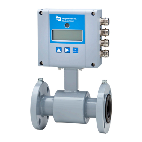
Badger Meter ModMAG M5000 User Manual
Electromagnetic flow meter
Hide thumbs
Also See for ModMAG M5000:
- User manual (32 pages) ,
- Installation manual (4 pages) ,
- User manual (24 pages)
Table of Contents
Advertisement
Quick Links
Advertisement
Table of Contents

Related Manuals for Badger Meter ModMAG M5000


Summary of Contents for Badger Meter ModMAG M5000
- Page 1 Electromagnetic Flow Meter M5000 User Manual MAG-UM-00219-EN-17 (June 2021)
-
Page 2: Table Of Contents
Electromagnetic Flow Meter M5000 CONTENTS Safety Precautions and Instructions . . . . . . . . . . . . . . . . . . . . . . . . . . . . . . . . . . . . . . . . . . . . . . . . . . . . . . . . . . . 5 Basic Safety Recommendations . - Page 3 User Manual Battery Life . . . . . . . . . . . . . . . . . . . . . . . . . . . . . . . . . . . . . . . . . . . . . . . . . . . . . . . . . . . . . . . . . . . . . . . 17 Battery Replacement .
- Page 4 Electromagnetic Flow Meter M5000 Wiring . . . . . . . . . . . . . . . . . . . . . . . . . . . . . . . . . . . . . . . . . . . . . . . . . . . . . . . . . . . . . . . . . . . . . . . . . . 44 Programming .
-
Page 5: Safety Precautions And Instructions
Safety Precautions and Instructions SAFETY PRECAUTIONS AND INSTRUCTIONS Some procedures in this manual require special safety considerations . In such cases, the text is emphasized with the following symbols: Indicates a hazardous situation, which, if not avoided, will result in death or serious personal injury . WARNING Indicates a hazardous situation, which, if not avoided, could result in death or serious personal injury . -
Page 6: Unpacking And Inspection
If the unit was damaged in transit, it is your responsibility to request an inspection report from the carrier within 48 hours . You must then file a claim with the carrier and contact Badger Meter for appropriate repairs or replacement . - Page 7 Unpacking and Inspection • Use the sling-rigged method to lift large detectors into a vertical position while they are still crated . Use this method to position while they are still crated . Use this method to position large detectors vertically into pipelines . Figure 2: Sling-rigged lifting methods •...
-
Page 8: System Description
System Description SYSTEM DESCRIPTION The Badger Meter model M5000 electromagnetic flow meter is intended for fluid metering in most industries including potable water, reclaimed water, food and beverage, pharmaceutical and chemical . The meter can measure all fluids with electric conductivity of at least 5 µS/cm (20 µS/cm for demineralized water) and is highly accurate . Measuring results depend on density, temperature and pressure . -
Page 9: Meter Location, Orientation And Applications
Meter Location, Orientation and Applications METER LOCATION, ORIENTATION AND APPLICATIONS The M5000 provides two amplifier mounting options: a meter mounted option and a remote option . Meter mounted option Remote option Figure 5: Amplifier mounting options Remote Option Use a remote amplifier in the following situations: •... -
Page 10: Protection Class
Meter Location, Orientation and Applications Protection Class The device has protection class IP 67, optional IP 68 . In order to fulfill requirements in respect of the protection class, follow these guidelines: • Body seals must be undamaged and in proper condition . •... -
Page 11: Meter Orientation
Meter Location, Orientation and Applications Meter Orientation Mag meters can operate accurately in any pipeline orientation and can measure volumetric flow in forward and reverse directions, as long as the pipe is completely full . OTE: A "Forward Flow" direction arrow is printed on the detector label . Vertical Placement Mag meters perform best when placed vertically, with liquid flowing upward and meter electrodes in a closed, full pipe . -
Page 12: Pipe Reducer Requirements
Meter Location, Orientation and Applications Pipe Reducer Requirements With pipe reducers, a smaller meter can be mounted in larger pipelines . This arrangement may increase low-flow accuracy . There are no special requirements for standard, concentric pipe reducers . Custom fabricated pipe reducers must have a maximum slope angle of 8 degrees to minimize flow disturbances and excessive loss of head . -
Page 13: Partially-Filled Pipe Situations
Meter Location, Orientation and Applications Partially-Filled Pipe Situations In some locations, the process pipe may be momentarily only partially filled . Examples include: lack of back pressure, insufficient line pressure and gravity flow applications . To eliminate these situations: • Do not install the meter at the highest point of the pipeline . -
Page 14: Meter Gaskets And Grounding
These grounding straps must be copper wire, at least 12 AWG size . They must be connected on both sides (inlet and outlet) of the detector and to a local, earth ground . To provide a good electrical connection at the mating flanges, Badger Meter recommends that you drill and tap the flanges and install a grounding screw (not provided) . -
Page 15: Non-Conductive Pipe Grounding
Meter Gaskets and Grounding Non-Conductive Pipe Grounding IMPORTANT If the process pipe is not electrically conductive (PVC, fiberglass, cement-lined pipes or any other non-conductive material) and the meter was not originally ordered with an optional grounding electrode, you must install a pair of grounding rings between the mating flanges at both ends of the meter. -
Page 16: Wiring
Wiring WIRING Wiring Safety WARNING • Disconnect power to the unit before attempting any connection or service . • Do not bundle or route signal lines with power lines . • Use twisted pair shielded wire for all output wiring . •... -
Page 17: Power
Power POWER The M5000 can be powered with: • Battery only (2 D-cells or 4 D-cells) • 100…240V AC (with battery back-up) • 9…36V DC (with battery back-up) Battery Use a two D-cell battery pack for sizes 1/2…6 in . (DN 15…150) or a double two D-cell battery pack for sizes 8…24 in . (DN 200…600) . -
Page 18: Battery Backup
Power Figure 24: Amplifier housing components – exploded view Battery Backup The backup battery option allows the meter to run using the backup battery power in case of power loss . The meter ships with an unplugged backup battery . Make sure that any power cables are of a sufficiently high current rating . If in doubt, contact your distributor . -
Page 19: Installation
Installation INSTALLATION For detectors with PTFE liner, do not remove protective cap on the flange until shortly before installation . Remote Mount Installation Mount Bracket to Amplifier 1 . Align bracket-mounting holes with amplifier mounting holes . 2 . Attach bracket to amplifier with supplied screws . Torque the screws to 80 inch-pounds . Wiring Configuration Connection on the amplifier 1 . - Page 20 Shield 13 12 COIL COIL 12 COIL 11 11 COIL Badger Meter JBOX - PRIMO REMOTE - REV1 Figure 31: Cables to plugs Wiring for Remote Configuration Remote style M5000 amplifier models can be ordered with standard cables measuring 15, 30, 50 and 100 feet (5, 10, 15, and 30 m) .
-
Page 21: Signal Cable Specification
Signal Cable Specification • Only use signal cables delivered by Badger Meter or corresponding cable in accordance with the following specification . • Take maximum signal cable length between detector and amplifier into account (keep distance as low as possible) . -
Page 22: Configuring Input/Output (I/O)
Configuring Input/Output (I/O) CONFIGURING INPUT/OUTPUT (I/O) This section describes wiring the following M5000 outputs: • Digital outputs • Communication When the sensor and the amplifier have been wired, wire any outputs to the M5000 amplifier . Follow all of the safety precautions and local code to prevent electrical shock and damage to the electronic components . Circuit Board Diagram RS 232 OUT 4... - Page 23 Configuring Input/Output (I/O) Jumper Location JP1 jumper for password activation Figure 34: JP1 location Digital Output Wiring Diagrams Positive Pulse Logic Negative Pulse Logic Figure 35: Digital output wiring diagram Digital Output Selections Output 1 Output 2 Output 3 Output 4 Flow direction Forward Pulse Output Reverse Pulse Output...
-
Page 24: User Interface
User Interface USER INTERFACE The M5000 amplifier is pre-programmed from the factory . No additional programming is necessary, however, for special features, the meter can be programmed for specific requirements . Function Buttons All M5000 programming is accomplished using the three function buttons located on the front of the amplifier . -
Page 25: Display
User Interface Display The top row displays seven digits for specific values on each screen and the bottom row displays meter and register condition icons and current screen descriptions . Icons Battery status Communication interface is activated (RS232, IrDA, M-Bus) Meter is unlocked Error message Empty pipe detection... -
Page 26: M5000 Main Menu Programming Options
M5000 Main Menu Programming Options M5000 MAIN MENU PROGRAMMING OPTIONS The following M5000 programming options are available from the Main Menu: • Meter Setup • Measure • In/Out • Communication • Battery • Miscellaneous • Information • • Faults The applicable security level for each menu option is indicated as follows: Administrative Service User... -
Page 27: Menu Structure
M5000 Main Menu Programming Options Menu Structure Flow rate Percent Login MainMenu MeterSet Calibration Diameter Detector Factor Scale Factor Detector Zero Frequency Amplifier Factor Period Coil Current Empty Pipe det. On Off Threshold Measured Measure FlowUnit Totalizer Unit Full Scale CutOff Flow Direction Totalizer1... - Page 28 M5000 Main Menu Programming Options MainMenu MeterSet Measure Input/Outputs Simulation Dig Input Outputs Puls/Unit Width Frequency SetMin SetMax OutFunction #1 Test MinMax EmptyPipe ErrorAlarm Forward Loopback Battery Alarm OutFunction #2 Test MinMax EmptyPipe ErrorAlarm Reverse Loopback Battery Alarm OutFunction #3 Test MinMax EmptyPipe...
- Page 29 M5000 Main Menu Programming Options MainMenu MeterSet Measure Outputs/Input Comunication Interface Irda Serial Serial Modbus M-Bus M-Bus Battery Power up counter Voltage Life time Operation time Capacity Ah Capacity % Limit % Battery change MISC Settling Time in ms Language English German Czech...
-
Page 30: Programming Menus
Programming Menus PROGRAMMING MENUS Meter Setup Menu Meter Setup Calibration Diameter Factory set . In the event the amplifier is replaced, verify that the pipe [Diameter] diameter matches the installed pipe size . Detector Factor Factory set . Compensates for accuracy error as a result of the [Det Fact] installed detector . -
Page 31: Measure Menu
Programming Menus Measure Menu Measure Flow Unit Establishes the unit of measure for the flow rate and full scale flow . Changing this parameter readjusts [Flow Unit] the full scale flow parameter . For example, changing from GPM to GPS would change the full scale flow from 60 gal/min to 1 gal/s . - Page 32 Programming Menus Measure Flow Direction Allows setting the meter to measure forward flow only (unidirectional) or both forward and reverse [Bi-directional] flow (bidirectional) . Unidirectional Flow is totalized in only one direction . The flow direction is indicated by the arrow printed on the detector label .
-
Page 33: Inputs/Outputs Menu
Programming Menus Inputs/Outputs Menu Inputs/Outputs Flow Simulation Provides output simulation based on a percentage of the full scale flow . Simulation does not [Simulat] accumulate the totalizers . The range of simulation includes –100…100% of the full scale flow . The parameter lets you set the range of simulation in increments of 50 (OFF, 0, 50, 100, –50, –100) . - Page 34 Programming Menus Inputs/Outputs Digital Outputs Set Minimum Establishes, as a percentage of full scale flow, the threshold at which the output (continued) [Set Min] alarm is activated . Flow rates below the threshold activate the output alarm . Set Maximum Establishes, as a percentage of full scale flow, the threshold at which the output [Set Max] alarm is activated .
-
Page 35: Communication Menu
Programming Menus Communication Menu Communication: Port Settings Interface Provides communication port configuration . [Interface] • IrDA (Modbus RTU) • Serial (Modbus RTU) OTE: Modbus RTU is only for programming the meter or reading the internal data logger . Extended use, even in standby mode, uses power and can drain the battery quickly . •... -
Page 36: Battery Menu
Programming Menus Battery Menu PwrUpCnt (Power Up Counter) A diagnostic counter of how many times the meter has reset or been power cycled (Read Only) (for instance, battery removed and replaced) . Voltage Displays the current battery voltage . (Read Only) Lifetime Displays the remaining battery life time in years depending on the currently selected parameters . -
Page 37: Miscellaneous Menu
Programming Menus Miscellaneous Menu Misc Settling The time the magnetic circuit takes to settle . An engineering diagnostic . [Read Only] Language Allows you to change the current language . English is the default setting . [Language] The following languages are supported: German (Deutsch), Czech (Cestina), Spanish (Espanol), French (Francais), Russian (России), Italian (Italiano) . -
Page 38: Information Menu
Programming Menus Information Menu Info Serial Number Serial number of the electronic board . [SerNum] (Read Only) Software Version Software version of the device . [Version] (Read Only) Compilation Date Date of the software version . [Compilat] (Read Only) OPT CRC Checksum of the software update . -
Page 39: Security
• OTE: For a lost PIN, contact Badger Meter Technical Support at 800-456-5023 . The security settings also apply to remote access . All remote writes via Modbus to the meter are blocked unless the user is remotely logged in . -
Page 40: Logging In
Users logged in with this PIN have access to all procedures . Users at this level have full access to the meter . Random Generates a random number which is used when a PIN is lost . This number is needed for Badger Meter Tech Support to provide a Master PIN . Emergency Enter the Master PIN received from Badger Meter Technical Support to unlock the meter in case the Admin PIN has been lost . -
Page 41: Maintenance
Maintenance MAINTENANCE Mandatory, routine or scheduled maintenance should not be required for the M5000 Electromagnetic Flow Meter electronics or flow tube after proper installation . However, some occurrences may require personnel to perform the following: • Flow tube and electrode cleaning •... -
Page 42: Troubleshooting
If the fluid measured has a high concentration of conductive solids, deposits may accumulate on the internal liner walls and electrodes . These deposits cause a reduction of the measuring output . Thus, Badger Meter recommends that you remove the meter and inspect the liner and electrodes after six months . If deposits are found, remove them with a soft brush . -
Page 43: Errors And Warnings
What You See Why It Happened How to Fix It MEASURE_TIMEOUT The board may be damaged . Contact Badger Meter Technical Support . COMMON_MODE_VOLTAGE_ Common mode voltage is smaller than Make sure the meter is properly grounded . OVERLOAD –2 .0V or larger than +4 .1V . -
Page 44: Connecting An Orion Rtr® Endpoint To The M5000 Meter
Connecting an ORION RTR® Endpoint to the M5000 Meter CONNECTING AN ORION RTR® ENDPOINT TO THE M5000 METER OTE: Connect the endpoint as described . If there is a reading on the M5000, program the endpoint to match that reading or reset the totalizer . -
Page 45: Connecting An Orion Encoder Endpoint To The M5000 Meter
Figure 37 . Figure 37: ORION Cellular LTE endpoint connection with resistor Order resistor kit P/N 69224-001 from Badger Meter . Programming Changing the following settings automatically configures Input and Output 4 for ADE . To program the M5000 meter for the endpoint to Output #1 (forward flow): 1 . -
Page 46: Specifications
Specifications SPECIFICATIONS OTE: Measurements in DN are for Nominal Diameter in mm . M5000 Amplifier Flow Range 0 .1…32 .8 ft/s (0 .03…10 m/s) Accuracy ± 0 .4% of measured value ± 2 mm/s OIML/MID: 2…12 in . (DN50…300) with 0d up and 0d downstream ±1% ≥ 1 .2 ft/s (0 .35 m/s) Repeatability ±... -
Page 47: Detector Type Vi
Specifications Detector Type VI Size 1/2…24 in . (DN 15…600) Flange Type DIN, ANSI, JIS, AWWA and more Process Connection Material Standard: carbon steel; optional: stainless steel 304/316 Pressure Limits Up to 1450 psi (100 bar) PED Meter Enclosure Classification Standard: NEMA 4X (IP67);... - Page 48 Specifications with ANSI-flanges with DIN-flanges Size A Std* A ISO** ø D ø K ø d2×n ø D ø K ø d2×n (DN) (mm) (mm) (mm) (mm) (mm) (mm) (mm) (mm) (mm) (mm) (mm) (mm) 2-1/2 11 .0 7 .87 10 .67 13 .03 16 .9...
-
Page 49: Error Limits
Specifications Error Limits Measuring range 0 .10…39 .37 ft/s (0 .03…12 m/s) Pulse output ±0 .4% of m .v . ±0 .08 in ./s (2 mm/s) Repeatability ±0 .1% of actual data Reference conditions Ambient and fluid temperature 68° F (20° C) Electr. -
Page 50: Oiml Approved Meter
OIML Approved Meter OIML APPROVED METER The M5000 is type approved according to the international water meter standards OIML R49 . The meter is approved as Class I and Class II for the detector sizes 2…12 inches (DN 50…300) . ±E% Cl. -
Page 51: Mid Approved Meter (Mi-001)
OIML Approved Meter MID Approved Meter (MI-001) The M5000 is type approved according to Directive 2004/22/EC of the European Parliament and Council of March 31, 2004 Measuring Instruments (MID) Annex MI-001 . The meter is approved for the detector sizes 2…12 inches (DN 50…300) . ±E% Cl. -
Page 52: Replacement Parts
Replacement Parts REPLACEMENT PARTS OTE: For remote applications, two cables are required: An electrode cable and a coil cable . Pos. Description North American Part no. International Part no. Amplifier assembly complete Complete without Batteries — 592603 Complete with 2 D-cells 66902-003 592600 Complete with 4 D-cells... - Page 53 Replacement Parts Pos. Description North American Part no. International Part no. Data logging kit (required for firmware update) 67354-008 — Verification device 66849-001 — PC programming kit via USB/RS232 — 592604 — PC programming kit via IrDA — 592605 Grounding ring kits (for specific sizes, refer to the parts price list 63528-xxx —...
- Page 54 Electromagnetic Flow Meter M5000 INTENTIONAL BLANK PAGE Page 54 MAG-UM-00219-EN-17 June 2021...
- Page 55 User Manual INTENTIONAL BLANK PAGE June 2021 MAG-UM-00219-EN-17 Page 55...
- Page 56 Control. Manage. Optimize. ModMAG and ORION are registered trademarks of Badger Meter, Inc . Other trademarks appearing in this document are the property of their respective entities . Due to continuous research, product improvements and enhancements, Badger Meter reserves the right to change product or system specifications without notice, except to the extent an outstanding contractual obligation exists .
Need help?
Do you have a question about the ModMAG M5000 and is the answer not in the manual?
Questions and answers