Badger Meter M Series Installation And Operation Manual
Mag meter
Hide thumbs
Also See for M Series:
- Installation and operation manual (43 pages) ,
- Connecting manual (2 pages)

Related Manuals for Badger Meter M Series


Summary of Contents for Badger Meter M Series
- Page 1 M-Series® Mag Meter Model M-2000 IMPORTANT: This manual contains important information. READ AND KEEP FOR REFERENCE. IOM-175-03 (4-11) Installation & Operation Manual PN: 53400-190 Rev 3...
- Page 2 Model M-2000 Mag Meter Page ii 4-11...
-
Page 3: Table Of Contents
Installation & Operation Manual CONTENTS Safety Precautions and Instructions ......................System Description............................. Unpacking and Inspection ......................... Rigging, Lifting and Moving Large Units ....................... Meter Location, Orientation and Applications ..................Remote Amplifier Outdoor Location ........................Pipelines and Fluid Flow ............................Meter Orientation ..............................Vertical Placement .............................. - Page 4 Model M-2000 Mag Meter External Disconnect ................................16 AC Power Wiring ..................................16 Remote Mount Installation ..........................Mount Bracket to Amplifier ..............................16 Wiring Configuration ................................16 Wiring for Remote Configuration ............................17 Empty Pipe Detection Considerations ..........................17 Configuring Input/Output (I/O) ....................... Analog Output Wiring Diagram ............................
-
Page 5: Safety Precautions And Instructions
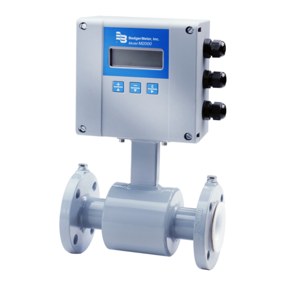
Comply with the instructions and proceed with care. System Description The Badger Meter M-Series® model M-2000 electromagnetic flow meter is intended for fluid metering in most industries including water, wastewater, food and beverage, pharmaceutical and chemical. The basic components of an electromagnetic flow meter are: • The detector, which includes the flow tube, isolating liner and measuring electrodes. -
Page 6: Unpacking And Inspection
Note: If the unit was damaged in transit, it is your responsibility to request an inspection report from the carrier within 48 hours. You must then file a claim with the carrier and contact Badger Meter for appropriate repairs or replacement. - Page 7 Installation & Operation Manual • Use the sling-rigged method to lift large detectors into a vertical position while they are still crated. Use this method to position while they are still crated. Use this method to position large detectors vertically into pipelines. •...
-
Page 8: Meter Location, Orientation And Applications
Model M-2000 Mag Meter Meter Location, Orientation and Applications The M-2000 provides two amplifier mounting options: an integral or meter mount option and a junction box/remote option. Meter mount amplifier Junction box with remote amplifier Remote Amplifier Outdoor Location The amplifier can be installed and operated outdoors. However, it must be protected from the elements, as follows: •... -
Page 9: Vertical Placement
Installation & Operation Manual Vertical Placement Mag meters perform best when placed vertically, with liquid flowing upward and meter electrodes in a closed, full pipe. Vertical placement allows the pipe to remain completely full, even in low flow, low pressure applications, and it prevents solids build-up, sediment deposit and accumulation on the liner and electrodes. -
Page 10: Straight Pipe Requirements
Model M-2000 Mag Meter Straight Pipe Requirements Sufficient straight-pipe runs are required at the detector inlet and outlet for optimum meter accuracy and performance. An equivalent of three diameters of straight pipe is required on the inlet (upstream) side. Two diameters are required on the outlet (downstream) side. -
Page 11: Chemical Injection Applications
– can also affect downstream readings by the meter. Sometimes, due to circumstances, it’s difficult to specify the exact downstream placement distances. Contact Badger Meter Technical Support to review your application if necessary. - Page 12 WRONG RIGHT WRONG RIGHT Model M-2000 Mag Meter Do not install the meter in a vertical, downward flow section of pipe. Always position the ON/OFF valves on the downstream side of the meter. RIGHT WRONG WRONG RIGHT Do not install in a vertical, downward position. Position "On/Off"...
-
Page 13: Meter Gaskets And Grounding
Installation & Operation Manual Meter Gaskets and Grounding Gasket and grounding requirements must be considered when determining the meter location, orientation and application. Meter/Pipeline Connection Gaskets You must install gaskets (not provided) between the detector's isolating liner and the pipeline flange to ensure a proper and secure hydraulic seal. -
Page 14: Non-Conductive Pipe Grounding
Model M-2000 Mag Meter Non-Conductive Pipe Grounding IMPORTANT If the process pipe is not electrically conductive (PVC, fiberglass, cement-lined pipes or any other non-conductive material) and the meter was not originally ordered with an optional grounding electrode, you must install a pair of grounding rings between the mating flanges at both ends of the meter. -
Page 15: Wiring
Installation & Operation Manual Wiring Wiring Safety At installation, be sure to comply with the following requirements: • Disconnect power to the unit before attempting any connection or service to the unit. • Do not bundle or route signal lines with power lines. •... -
Page 16: Power Connections
Model M-2000 Mag Meter Power Connections External Disconnect Install an external disconnect switch or circuit breaker that meets local standards. Position the M-2000 in an accessible location. Position and identify the disconnect device so as to provide safe and easy operation. Label the disconnect device as being for the mag meter. -
Page 17: Wiring For Remote Configuration
Installation & Operation Manual Wiring for Remote Configuration shield (black) green pink yellow CS C2 C1 shield (black) brown shield (black) white white shield (black) brown shield (black) pink yellow shield (black) green Remote style M-2000 amplifier models can be ordered with standard cables measuring 15, 30, 50 and 100 feet. In addition, cables up to 500 feet are available. -
Page 18: Configuring Input/Output (I/O)
Model M-2000 Mag Meter Configuring Input/Output (I/O) This section describes wiring the following M-2000 inputs/outputs: • Analog output • Digital input • Digital outputs • Communication Once the sensor and the amplifier have been wired, wire any inputs and outputs to the M-2000 amplifier. Do not connect the main power connection until you have made all other wiring connections. -
Page 19: Analog Output Wiring Diagram
Installation & Operation Manual Input/Output Description Terminal Analog Output 0-20 mA Resistive Load < 800 ohms 16 (+) 4-20 mA Resistive Load < 800 ohms 15 (-) 0-10 mA Resistive Load < 800 ohms 2-20 mA Resistive Load < 800 ohms Digital Output 1 Passive max. -
Page 20: Digital Output Wiring Diagrams
Model M-2000 Mag Meter Digital Output Wiring Diagrams Digital Input Wiring Diagram Page 20 4-11... -
Page 21: Programming The M-2000
Installation & Operation Manual Programming the M-2000 The M-2000 amplifier comes preprogrammed from the factory. Typically, you will not need to do any additional programming. However, to take advantage of special features, you can program the meter for your specific needs. If you will be programming the meter, familiarize yourself with the M-2000 Function Buttons and follow the procedures outlined below. -
Page 22: Function Buttons
Model M-2000 Mag Meter Note: The bottom line of a numeric-value display provides prompts regarding the function of each button. The [+] or [-] button will change the value of the numeral. The [E] button will move the cursor one digit to the right. When the cursor is at the final, right-most digit, pressing [E] will reposition the cursor at the left-most digit. - Page 23 Installation & Operation Manual Consider the Down Arrow [ - | ↓ ] button as the "previous step" button. During a procedure, pressing this button will go to the menu's previous selection or decrement a numeral. Example 1: The illustration below shows the M-2000 Main Menu. The selection arrow is pointing to the Meter Setup selection.
-
Page 24: Security
Model M-2000 Mag Meter Security The M-2000 security feature gives you the option to restrict access to the meter by way of a five-digit Personal Identification Number (PIN). The system administrator can set up a single PIN for each of the three different levels of access: •... -
Page 25: Entering Your Personal Identification Number (Pin)
PIN, pressing [E] from the Start Screen opens the Main Menu. If you forget or misplace your PIN, call Badger Meter Customer Service to get a master password. When you call, have the security code that appears in the upper right corner of the PIN Request display. -
Page 26: Setting Up The M-2000 With Quick Setup
Model M-2000 Mag Meter Setting Up the M-2000 with Quick Setup The M-2000 provides you with a Quick Setup utility that allows you to set or change your Flow Units, Totalizer Units, Full Scale Flow and Low Flow Cutoff settings. To open the Quick Setup, select Quick Setup from the Start menu. Quick Setup Flow Unit Flow Unit lets you set the unit of measure for the flow rate and full scale flow. - Page 27 Installation & Operation Manual Quick Setup Full Scale Flow This parameter sets the maximum flow the system is expected to measure. This parameter has influence on other system parameters. These parameters include: • Frequency Output – Full scale frequency is observed at full scale flow • Low Flow Cutoff –...
-
Page 28: Using The M-2000'S Main Menu Programming Options
Options that can be set at Quick Setup are indicated with: The factory default values are shown, enclosed in brackets. Note: Options that are listed [Factory Set] should not be changed without specific directions from authorized Badger Meter personnel. Meter Setup Scale Factor Changing the scale factor lets you adjust the meter's accuracy without disturbing factory-set parameters. - Page 29 Installation & Operation Manual Meter Setup Power Line Freq This parameter provides measuring immunity to industrial noise from a power supply feed. [60 Hz] To set Power Line Frequency, follow these steps from the Meter Setup menu: 1. Select Power Line Freq to view the Power Line Frequency display. 2.
- Page 30 Model M-2000 Mag Meter Meter Setup Detector Factor This parameter is set at the factory. This factor compensates for accuracy error as a result of the installed detector. If accuracy adjustment of the meter is required, please refer to the scale factor. [Factory Set] In the event the amplifier is replaced, this parameter must be reprogrammed with the original detector factor.
- Page 31 Installation & Operation Manual Measurements Totalizer Unit This parameter establishes the units of measure for the totalizers. [USG] To change the Totalizer Unit value, follow these steps from the Measurements menu: 1. Select Totalizer Unit to view the Totalizer Unit display. ...
- Page 32 Model M-2000 Mag Meter Measurements Low Flow Cutoff Low flow cutoff defines the threshold at which flow measurement will be forced to zero. The cutoff value can be set from 0% to 10% of the full scale flow. Increasing this threshold will help prevent false [0.2%] readings during “no flow”...
- Page 33 Installation & Operation Manual Inputs/Outputs Analog Output Range This parameter establishes the range of the analog output signal. To change Analog Output range, follow these steps from the Inputs/Outputs menu: [4 to 20 mA] 1. Select Analog Output to view the Analog Output display. 2.
- Page 34 Model M-2000 Mag Meter Inputs/Outputs Digital Output Pulses/Unit The Pulses/Unit parameter lets you set how many pulses per unit of measure will be transmitted to remote applications. For example, assuming the unit of measure is gallons: • Setting the Pulses/Unit to 1 will transmit 1 pulse every gallon • Setting the Pulses/Unit to 0.01 will transmit 1 pulse every 100 gallons You must configure pulses/unit if the function of the selected output is to be forward, reverse or AMR pulse.
- Page 35 Installation & Operation Manual Inputs/Outputs Digital Output Preset Amount Preset amount lets you set the reset value for the associated PS totalizer when the digital input is set to Batch Reset. [0.0] To change the preset amount, follow these steps from the Inputs/Outputs Menu: 1.
- Page 36 Model M-2000 Mag Meter Inputs/Outputs Digital Output Output Type The Output Type parameter lets you set the output switch to normally open or normally closed. If normally open is selected, the output switch is open [1: Normally Open] (no current) when the output is inactive, and closed (current flows) when the output is active.
- Page 37 Installation & Operation Manual Inputs/Outputs Digital Output Select Function Digital Output lets you configure the functional operation of the associated output. The following operations are supported: [1: Forward Pulse] • Reverse Pulse – Generates pulses during reverse flow conditions [2: Reverse Pulse] • Forward Pulse –...
- Page 38 Model M-2000 Mag Meter Clear Totals The uni-directional totalizer is reset within the the menu manager or through remote communications. Clearing T1 also clears the associated rollover counter. The uni-directional totalizer is reset within the the menu manager, through remote communications or with properly-configured digital input (function = remote reset).
- Page 39 Installation & Operation Manual Communication: Port Settings Port Address This parameter establishes the Modbus RTU address. Modbus RTU requests will only be processed if the configured port address of the meter matches the request address found in the Modbus RTU packet. The range of addresses supported by Modbus RTU is 1-247.
- Page 40 Model M-2000 Mag Meter Communication: Port Settings Stop Bits This parameter configures the port stop bits. The following stop bits are supported: [1 Stop Bit] • 1 Stop Bit • 2 Stop Bits To change the stop bits, follow these steps from the Port A Settings menu: 1.
- Page 41 Installation & Operation Manual Advanced Unit Multiplier This Unit Multiplier establishes the number of units of measure that have to accumulate before the display totalizers are updated. This is also known as setting the number of “dead” zeroes in the [Off ] display totalizer.
- Page 42 Model M-2000 Mag Meter Advanced Analog Calibrate Custom Settings Scale/Full Scale offsets on site. [Zero Scale: 0 mA] To set the analog calibration custom settings, follow these steps from the Advanced menu: [Full Scale: 0 mA] 1. Select Analog Calibrate to view the Analog Calibrate menu. 2.
- Page 43 Installation & Operation Manual Advanced Software Filter Description The software filter operates as an acceleration filter. This filter when configured properly allows for filtering of fast changes in fluid flow. Generally, this filter is used in applications having highly conductive fluids. This filter is intended to help provide smoothing of the analog output and display fluctuations.
- Page 44 Model M-2000 Mag Meter Advanced Software Filter Constant Flow During normal flow conditions, there is always a non-zero acceleration component. [150 M /Sec For example, if acceleration of the flow activates the filter, the meter will assume constant flow for the duration of the filter delay time unless the flow returns within limits.
- Page 45 Installation & Operation Manual Advanced Empty Pipe Cal. Fluid conductivity impacts the performance of empty pipe measurements. If you require empty pipe detection, you should perform this empty pipe calibration procedure. [Default] Before starting the empty pipe calibration, verify that empty pipe detection is enabled. Also, run both the empty pipe and the full pipe calibration procedures.
- Page 46 Model M-2000 Mag Meter Advanced Security Set Admin PIN Users logged in with this PIN will have access to all M-2000 procedures. [00000] To set the administrator's PIN, follow these steps from the Advanced Menu: 1. Select Security to view the Security menu. 2.
- Page 47 Installation & Operation Manual Info/Help Error Counts Description This menu provides a diagnostic view of the meter’s performance. Below are several system diagnostic counters and their definitions. Use discretion when interpreting these counters. These values could be altered during system setup or when using the verification device.
- Page 48 Model M-2000 Mag Meter Info/Help The number of times the totalizers have rolled over 9,999,999,999 (10 billion). Rollover Counts As the meter rolls over, a status indicator appears in the display. When this occurs, we suggest that you record the totalizers and rollover counter and reset the totalizers. Resetting totalizers will also clear the rollover counter.
- Page 49 Installation & Operation Manual Info/Help Restore Defaults Restores all non-calibrated parameters to the factory defaults. [Not applicable] Restore Calibration Restores the meter calibration as set at the factory. [Not applicable] Language Select Language Select The M-2000 supports one alternate language along with English. This alternate language choice is set at the factory.
-
Page 50: Maintenance
Model M-2000 Mag Meter Maintenance Mandatory, routine or scheduled maintenance should not be required for the Badger M-2000 Mag Meter electronics or flow tube after proper installation. However, some occurrences may require personnel to perform the following: • Flow tube and electrode cleaning •... -
Page 51: Troubleshooting
Troubleshooting The M-2000 mag meter is designed for many years of optimal performance. However, should it malfunction, there are certain things that we recommend you check before contacting our Technical Support department or your local Badger Meter Representative. Note: If the fluid measured has a high concentration of conductive solids, deposits may accumulate on the internal liner walls and electrodes. - Page 52 Model M-2000 Mag Meter Menu Manager Configuration Errors Error Description Recommended Action Output 1/2: Pulse Output This error is observed when improperly configuring the full scale flow, pulse per unit, or pulse width. Configuration Error This error can indicate the following configuration violations: Pulse frequency exceeds limits at full scale flow Pulse duty cycle is less than 50% at full scale flow (pulse on time >...
-
Page 53: Appendix: Detector Specifications
Installation & Operation Manual Appendix: Detector Specifications Meter with M-2000 amplifier Meter with junction box for remote M-2000 amplifier Est. Weight Flow Range Size with M-2000 inch inch inch inch inch 14.0 11.4 0.063 0.02 5/16 14.0 11.4 0.114 0.03 14.0 11.4 0.177... -
Page 54: Appendix: Amplifier Specifications
Model M-2000 Mag Meter Appendix: Amplifier Specifications 3.3" (83 mm) 0.2" 1.3" 7.1" 1.1" (6 mm) (34 mm) (180 mm) (27 mm) 1.9" 7.1" (47 mm) (180 mm) 1.9" (47 mm) 11" (280 mm) 0.2" (5.5 mm) 2.4" (60 mm) 2.6"... - Page 55 Installation & Operation Manual Page 55 4-11...
- Page 56 M-Series is a registered trademark of Badger Meter, Inc. Other trademarks appearing in this document are the property of their respective entities. Copyright 2011, Badger Meter, Inc. All rights reserved. Due to continuous research, product improvements and enhancements, Badger Meter reserves the right to change product or system specifications without notice, except to the extent an outstanding contractual obligation exists.
Need help?
Do you have a question about the M Series and is the answer not in the manual?
Questions and answers