Table of Contents
Advertisement
Quick Links
1 VX-2S-OP-30X - Camera Information
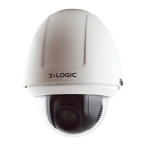
1.1 VX-2S-OP-30X Speed Dome PTZ Camera Overview
The figures below are for reference only.
Overview - VX-2S-OP-30X
Figure 1-1
1.2 VX-2S-OP-30X - Cable Interfaces
The cabling harness of the PTZ speed dome is shown in Figure 1-3. The cables are identified by different colors. Refer
to the labels attached on the cables for identification.
NOTE:
Make certain the speed dome is powered off before you connect the cables.
n
RS-485 Cable
Network Cable
Power Cord
Alarm Cable
Audio Cable
Video Cable
Figure 1-3
VISIX SOLUTIONS | VX-2S-OP-30X QUICK START GUIDE | p.1
Camera Inputs / Outputs
Memory Card Slot
Figure 1-2
Cable Interfaces
Input/Outputs
Advertisement
Table of Contents

Related Manuals for 3xLogic VX-2S-OP-30X


Summary of Contents for 3xLogic VX-2S-OP-30X
- Page 1 VISIX SOLUTIONS | VX-2S-OP-30X QUICK START GUIDE | p.1 1 VX-2S-OP-30X - Camera Information 1.1 VX-2S-OP-30X Speed Dome PTZ Camera Overview The figures below are for reference only. Camera Inputs / Outputs Memory Card Slot Overview - VX-2S-OP-30X Figure 1-1 Input/Outputs Figure 1-2 1.2 VX-2S-OP-30X - Cable Interfaces The cabling harness of the PTZ speed dome is shown in Figure 1-3. The cables are identified by different colors. Refer to the labels attached on the cables for identification. NOTE: Make certain the speed dome is powered off before you connect the cables. Power Cord RS-485 Cable Alarm Cable Audio Cable Video Cable Network Cable Cable Interfaces Figure 1-3...
- Page 2 VISIX SOLUTIONS | VX-2S-OP-30X QUICK START GUIDE | p.2 1.3 VX-2S-OP-30X - Alarm Output Diagram Alarm output is shown in Figure 1-4. Output DC 30V JQC-3FG Relay Power Supply (10A 250VAC) Direct load OUT (n) Relay Output ~220V AC Relay Output Zero OUT (n) OUT (n) FireWire Line OUT (n) Alarm Output Figure 1-4...
-
Page 3: Wall Mounting
VISIX SOLUTIONS | VX-2S-OP-30X QUICK START GUIDE | p.3 2 VX-2S-OP-30X Installation Before you start: Check the package contents and make sure that the device in the package is in good condition and all the assembly parts are included. NOTE: Do not touch the bubble shield directly by hand. The camera image may appear blurred as a result. Do not power the speed dome on until installation is finished. To ensure the safety of personnel and equipment, all the installation steps should be completed with power supply off. Do not lift or drag the speed dome by its cables; otherwise the performance of the unit’s weatherproofing may be affected. Do Not Pickup or Drag by Cables Figure 2-1 Mounting options are described in the proceeding sections. 2.2 Wall Mounting This mount must be purchased separately. 3xLOGIC Product Number: VX-WM-PTZ (Wall Mount) 2.2.1 WALL MOUNT Wall Mount - VX-WM-PTZ Applicable to indoor/outdoor pendant domes. - Page 4 VISIX SOLUTIONS | VX-2S-OP-30X QUICK START GUIDE | p.4 NOTE: For cement walls, you need to use the expansion screws to fasten the bracket. The mounting hole of the expansion pipe on the wall should align with the mounting hole on the bracket. For wooden walls, you can just use the self-tapping screw to fasten the bracket. Make sure that the wall is strong enough to withstand more than eight times the weight of the speed dome and its accessories. The bracket in Figure 2-9 is the recommended bracket for this series of speed dome, and a pendent adapter is required if any other bracket is selected. The dimension of pendant adapter is G1 Steps: Loosen the two lock screws on both sides of the speed dome. NOTE: Only loosen the screws. Do not remove the lock screws from the speed dome. Back Box Lens Cover Bubble Protective Foam Remove the Bubble Figure 2-4 Pull the bubble to separate it from the back box, and remove the protective accessories. Protective Sticker Remove the Protective Accessories for Separated Speed Dome Figure 2-5...
- Page 5 VISIX SOLUTIONS | VX-2S-OP-30X QUICK START GUIDE | p.5 PoE+ and Hi-PoE Switch Figure 2-7 NOTE: If you choose Hi-PoE, a Hi-PoE adapter must be connected. The Hi-PoE module connection is shown in Figure 2-8. 1: Power Indicator 2: PORT Indicator 3: DATA & POWER OUT 4: DATA IN Network Speed Dome Ethernet Hi-PoE Connection Figure 2-8 Connecting Hi-PoE Steps: 1) Connect the Hi-PoE module to the Internet via the DATA IN interface using a network cable. 2) Connect the Hi-PoE module to the speed dome via the DATA & POWER OUT interface using a network cable. 3) Power on the Hi-PoE module. Install the memory card (optional). Align the cuts on the bubble with the lock screws on the back box to reinstall the bubble. Tighten the lock screws.
- Page 6 VISIX SOLUTIONS | VX-2S-OP-30X QUICK START GUIDE | p.6 Safety Rope Hang the Safety Rope Figure 2-10 Loosen the two lock screws on the bracket. Fasten the speed dome to the bracket. Rotate the speed dome clockwise tightly. Secure the two lock screws with the wrench. Lock Screw Lock Screw Install the Speed Dome to the Bracket Figure 2-11 Remove the protective film on the bubble after the installation is finished.
-
Page 7: Corner Mounting
VISIX SOLUTIONS | VX-2S-OP-30X QUICK START GUIDE | p.7 2.3 Corner Mounting This mount and adapter must be purchased separately. 3xLOGIC Product Number: VX-WM-PTZ (Wall Mount), VX-CM-PTZ (Corner Mount Adapter) 2.3.1 CORNER MOUNT COMPONENTS Wall Mount - VX-WM-PTZ You can use the wall mount with the corner adapter or pole adapter according to the needs of the installation environment. Wall Mount Figure 2-12 Corner Adapter - VX-CM-PTZ Please use the corner adapter with the wall mount in the corner mounting applications. Corner Adapter Figure 2-13 Mounting Accessories Hex Screws (M8×30), Nuts, Spring Washers and Flat Washers Figure 2-14... -
Page 8: Corner Mount Installation
VISIX SOLUTIONS | VX-2S-OP-30X QUICK START GUIDE | p.8 2.3.2 CORNER MOUNT INSTALLATION Before you start: The corner mount is intended to be installed solid 90-degree corners. The following are the mandatory preconditions for corner mounting: The wall must be thick enough to install the expansion screws. The wall must be strong enough to withstand more than 8 times the weight of the dome and its accessories. Steps: Install the corner adapter. Steps: (1) Drill four holes in the corner according to the screw holes of the corner adapter, and then insert M8 expansion screws (not supplied) into the holes. (2) Pull the cables through the center hole of the corner adapter. (3) Attach the corner adapter to the corner by aligning the 4 screw holes of the corner adapter with expansion screws on the corner. (4) Secure the corner adapter to the corner with the nuts and washers to tighten the four expansion screws. -
Page 9: Pole Mounting
VISIX SOLUTIONS | VX-2S-OP-30X QUICK START GUIDE | p.9 Secure the Wall Mount to the Corner Figure 2-15 Install the speed dome to the mount. Please refer to Section 2.2.1 Wall Mount for installation details. NOTE: Follow the same instructions described above for the short-arm wall mounting. For outdoor applications, please adopt water-proof installation measures. The short-arm wall mount is not recommended for outdoor applications. 2.4 Pole Mounting This mount and adapter must be purchased separately. 3xLOGIC Part Number: VX-WM-PTZ (Wall Mount), VX-POLE-PTZ (Pole Mount Adapter) 1.1.1 POLE MOUNT COMPONENTS Wall Mount - VX-WM-PTZ Please use the wall mount with corner adapter or pole adapter per the needs of the installation environment. Wall Mount Figure 2-16 Pole Adapter - VX-POLE-PTZ Please use the pole adapter with the wall mount for environments requiring pole mounting... -
Page 10: Pole Mount Installation
VISIX SOLUTIONS | VX-2S-OP-30X QUICK START GUIDE | p.10 Pole Adapter Figure 2-17 Pole Mounting Hoops Intended for use with the pole adapter. The following dimensions of stainless steel hoops are optional: φ59-82mm, φ84-108mm, φ103-127mm, φ130-152mm, φ155-178mm, φ180-203mm, φ194-216mm. Note: The dimensions of the pole mounting hoop must match the diameter of the pole adapter. Stainless Steel Hoops Figure 2-18 Mounting Accessories Hex Screws (M8×30) and Spring Washers Figure 2-19 1.1.2 POLE MOUNT INSTALLATION Before you start: The pole mounting is dependent on the indoor/outdoor solid pole construction. The following are the mandatory preconditions for mounting: The mounting dimensions of the stainless steel hoops must meet the diameter of pole. The pole construction must be strong enough to withstand more than 8 times the weight of the dome and its accessories. - Page 11 VISIX SOLUTIONS | VX-2S-OP-30X QUICK START GUIDE | p.11 Steps: Assemble the pole adapter. (1) Loosen the three stainless steel hoops with a screwdriver. (2) Insert them through the rectangle holes of the pole adapter. Assemble the Pole Adapter Figure 2-20 Install the pole adapter. (1) Pull the cables through the center hole. (2) Secure the three stainless steel hoops to the pole, and tighten the screws of the hoops with a screwdriver. Install the Pole Adapter Figure 2-21 NOTE: For outdoor applications, please adopt the water-proof measures. Install the wall mount. (1) Attach the gasket then wall mount to the pole adapter. (2) Secure the wall mount to the pole adapter with 4 hex screws and the spring washers.
-
Page 12: In-Ceiling Mounting
VISIX SOLUTIONS | VX-2S-OP-30X QUICK START GUIDE | p.12 Install the Wall Mount Figure 2-22 Install the speed dome to the mount. Please refer to Section 2.2.1 Wall Mount for installation details. NOTE: Follow the same instructions described above for the short-arm wall mounting. For outdoor applications, please adopt the water-proof measures. The short-arm wall mount is not recommended for outdoor applications. 2.5 In-Ceiling Mounting 2.5.1 IN-CEILING MOUNT APPLICATION Before you start: The in-ceiling mounting option is intended for indoor ceilings. The following are the mandatory preconditions for mounting: The height of the space above the ceiling must be more than 250mm. The thickness of the ceiling must range from 5 to 40mm. The ceiling must be strong enough to withstand more than 4 times the weight of the dome and its accessories. 2.5.2 IN-CEILING MOUNT INSTALLATION Before you start: The height of the space above the ceiling must be more than 250 mm. The thickness of the ceiling must range from 5 mm to 40 mm. The ceiling must be strong enough to withstand more than four times the weight of the speed dome and the accessories. Steps: Rotate the bubble counterclockwise to separate it from the back box. Remove the protective lens cover, foam, and sticker from the dome drive. Install the memory card (optional). Attach the bubble to the back box, and rotate clockwise to secure it. - Page 13 VISIX SOLUTIONS | VX-2S-OP-30X QUICK START GUIDE | p.13 Protective Foam Back Box Bubble Protective Sticker Remove the Protective Accessories Figure 2-23 Drill a hole on the ceiling according to the drill template (supplied). NOTE: ±2 mm of the circle diameter is allowable. Φ 224 Unit: mm Drill a Hole on the Ceiling Figure 2-24 Connect the cables. Install the speed dome to the ceiling. Loosen the two lock screws on both sides of the back box and position the locks internally as shown in Figure 2- 25. Lock Lock Locks and Lock Screws Figure 2-25 Push the speed dome into the mounting hole in the ceiling. Tighten the lock screws with a screwdriver and the locks will automatically rotate outwards to secure the in- ceiling bracket to the ceiling.
-
Page 14: Ceiling Mounting
VISIX SOLUTIONS | VX-2S-OP-30X QUICK START GUIDE | p.14 Ceiling Lock Install the Back Box Figure 2-26 Install the flange. Attach the flange to the bubble and align the triangular notch of the trim ring with the arrow label on the in- ceiling bracket. Firmly place the flange against the ceiling and rotate the flange in the direction of the arrow to secure it. Arrow Label Notch Install the Flange Figure 2-27 Remove the protective film on the bubble after the installation is complete. 2.6 Ceiling Mounting 2.6.1 CEILING MOUNT APPLICATION Before you start: The ceiling mounting is intended for indoor/outdoor solid ceilings. The following are mandatory preconditions for ceiling mounting: The thickness of the ceiling must range from 5mm to 40mm. The ceiling must be strong enough to withstand more than 4 times the weight of the dome and its accessories. If the speed dome is to be fastened to a wooden ceiling, use the self-tapping screws to secure the mounting base. If the speed dome is to be fastened to a cement ceiling, drill three Φ5 mm screw holes into the ceiling according to the position of the holes, and then secure the mounting base to the ceiling with expansion screws. 2.6.2 REMOVING THE IN-CEILING MOUNT The speed dome is installed with an in-ceiling mount by default. Before you mount the speed dome on the ceiling, you need to remove the in-ceiling mount first. Steps: Loosen and remove the 4 screws as shown in Figure 2-28. - Page 15 VISIX SOLUTIONS | VX-2S-OP-30X QUICK START GUIDE | p.15 Remove the Screws Figure 2-28 Remove the in-ceiling mount. Remove the Mount Figure 2-29 Install 4 bolts to the screw holes as shown in Figure 2-30. Install the bolts Figure 2-30...
-
Page 16: Wiring For Ceiling Mounting Applications
VISIX SOLUTIONS | VX-2S-OP-30X QUICK START GUIDE | p.16 2.6.3 WIRING FOR CEILING MOUNTING APPLICATIONS The cables of dome can be routed either from the top or the side of the back box, as shown in Figure 2-31. For the cables routed from the top of the back box, it is required to drill a cable hole in the ceiling. Cabling for Ceiling Mounting Figure 2-31 2.6.4 CEILING MOUNT INSTALLATION Steps: The ceiling mounting speed dome is installed with an in-ceiling bracket by default. You need to remove the in- ceiling bracket first before you install the speed dome. Loosen and remove the four screws as shown in Figure 2-32. Remove the Screws Figure 2-32 Remove the in-ceiling bracket as shown in Figure 2-33. - Page 17 VISIX SOLUTIONS | VX-2S-OP-30X QUICK START GUIDE | p.17 Remove the Bracket Figure 2-33 Install four bolts to the screw holes as shown in Figure 2-34. Install the bolts Figure 2-34 Route the cables. The cables of speed dome can be routed either from the top or the side of the back box, as shown in Figure 2-35. For the cables routed from the top of the back box, it is required to drill a cable hole in the ceiling. Cabling for Ceiling Mounting Figure 2-35 Install the speed dome. Rotate the bubble counterclockwise to separate it from the back box. Remove the protective lens cover, foam, and sticker from the dome drive. Attach the bubble to the back box, and rotate clockwise to secure it. Use the mounting base as a template to mark four screw holes onto the ceiling. If you route cables from the top of the back box, mark the cable hole on the ceiling and drill a hole. Secure the mounting base to the ceiling with the set screws.
- Page 18 VISIX SOLUTIONS | VX-2S-OP-30X QUICK START GUIDE | p.18 Screw Holes Cable Hole Secure the Mounting Base Figure 2-36 Route the cables for the speed dome. Align the bottom of the speed dome with the mounting base. Line up the direction of the arrow with the spring end of the mounting base. Push the speed dome upwards and then forwards in the direction of the arrow. When the speed dome is placed in position, the spring will automatically snap into the lock clip firmly as shown in Figure 2-37. Push Forwards Line up Push Upwards Attach the Back Box to the Mounting Base Figure 2-37 Remove the protective film on the bubble after the installation is finished.
-
Page 19: Lan Wiring
VISIX SOLUTIONS | VX-2S-OP-30X QUICK START GUIDE | p.19 3 Networking the Camera - LAN NOTE: The use of this product with Internet access always presents network security risks. To best safeguard your network against attacks or information leakage, always strengthen your network security by observing the latest security protocols and practices. Always use a complex password. If the product does not work properly or malfunctions, contact technical support, your dealer or the nearest service center. To ensure the network security of the speed dome, we recommend you to have the speed dome assessed and maintained regularly. 3.1 LAN Wiring To view and configure the speed dome via LAN (Local Area Network), you need to configure the camera to reside in the same subnet as your PC / VIGIL Server system. Then, use the 3xLOGIC Camera (VISIX IP) Setup Utility to identify and change the IP address of the camera. Finally, use the utility to add the camera to a VIGIL Server system. Connect the speed dome to the network per the following figures. Network Cable Network Speed Dome Computer Connecting Directly Figure 3-1 网络交换机 Network Speed Dome Computer Wiring over LAN Figure 3-2 3.2 Activating and Identifying the Camera... -
Page 20: Activating The Camera
VISIX SOLUTIONS | VX-2S-OP-30X QUICK START GUIDE | p.20 3.2.1 ACTIVATING THE CAMERA When setting up the camera for the first time, the camera must be activated by creating a complex password. This is a standard security practice and is required for access to the device. To activate the camera: Steps: Launch the utility. Click Detect Online Devices / Change IP Address. : 3xLOGIC Camera (VISIX IP) Setup Utility Figure 3-3 Select the camera from the list of online devices. If you are configuring the camera for initial setup, click Activate to assign a new password. This step is required for security purposes and must be completed before continuing. If the camera has previously been configured and activated, skip to the next section. 3.2.2 IDENTIFYING AND CHANGING THE IP ADDRESS Once you have assigned a complex password to the camera, click Change IP Address and change the IP address and subnet mask to the required values as defined in your site setup plan. Save the settings. - Page 21 VISIX SOLUTIONS | VX-2S-OP-30X QUICK START GUIDE | p.21 : 3xLOGIC Camera (VISIX IP) Setup Utility – Changing Device IP Address Figure 3-4 You can now enter the IP address of network camera in the address field of a web browser to access the camera’s web UI. For more details, proceed to Section 4.1 Error! Reference source not found.. For instructions on adding the camera to VIGIL Server, proceed to Section 4.2 Adding the Camera to VIGIL Server.
-
Page 22: Accessing The Camera Via Web Browser
VISIX SOLUTIONS | VX-2S-OP-30X QUICK START GUIDE | p.22 4 Operating the Camera – Quick Start 4.1 Accessing the Camera via Web Browser System Requirements: Operating System: Microsoft Windows XP SP1 and above version/Vista/Win7/Server 2003/Server 2008 32bits CPU: Intel Pentium IV 3.0 GHz or higher RAM: 1G or higher Display: 1024 × 768 resolution or higher Web Browser: Internet Explorer 7.0 and above version, Apple Safari 5.02 and above version, Mozilla Firefox 5 and above version and Google Chrome8 and above version Steps: Open a web browser. Input the IP address of the network camera in the URL address bar, e.g., 192.0.0.64 and press the Enter key to enter the login interface. Alternatively, if the camera is interfaced with VIGIL Server, the web UI can be instantly deployed by opening the camera’s Network Settings form in VIGIL Server Settings > Cameras Tab and clicking the Web Settings button. Input the user name and password and click Login. NOTE: The username/password for the camera will have been configured during camera activation If the camera has already been configured using one of 3xLOGIC’s setup tools (VIGIL Easy Setup Wizard, 3xLOGIc Camera Setup Utility) then default credentials will have been changed by the installer (this is a standard security precaution enforced by the setup tools). Contact your security network administrator for credentials. NOTE: English is the only supported language. Login Interface Figure 4-1 To view video and have full access to the camera’s configuration settings, you will need to install the Web Components plug-in. Click Activate Web Components to start the plug-in installation. Follow the on-screen... - Page 23 VISIX SOLUTIONS | VX-2S-OP-30X QUICK START GUIDE | p.23 4.2 Adding the VX-2S-OP-30X to VIGIL Server Purpose: By following the steps outlined in this section, a user can add a camera to VIGIL Server using the 3xLOGIC Camera (VISIX IP) Setup Utility. The utility was previously utilized in Section 3.2 to detect and change the camera’s IP address. This utility is installed alongside VIGIL Server and will launch automatically when following the below steps. Steps: Login to VIGIL Server. Open the Settings > Camera Setup Tab. Select an unused camera channel to associate with the camera. Toggle the Network Camera checkbox. The Network Camera Settings form will deploy. If the form does not deploy automatically, click the Network Camera - Settings button. Click the Detect Cameras button located next to the Type field. The 3xLOGIC Camera Setup Utility will deploy and will automatically begin detecting devices on the network. Launching the 3xLOGIC Camera Setup Utility Figure 4-2 Select the desired camera from the list of online devices and click Next. 3xLOGIC Camera (VISIX IP) Setup Utility – Selecting Camera from Onlne Devices List Figure 4-3 After the utility successfully accesses the camera, click Save to VIGIL. A window will deploy where the user can assign the camera’s stream profiles. NOTE: If the utility fails to access the camera, confirm the utility is using the correct log-in credentials for the camera (created during camera activation) and re-attempt saving to VIGIL. If issues persist, contact 3xLOGIC Support.
- Page 24 VISIX SOLUTIONS | VX-2S-OP-30X QUICK START GUIDE | p.24 Assigning Stream Profiles Figure 4-4 Assign the streams as desired and click OK. The user will be returned to the Network Camera Settings form. To enable PTZ for the camera: On the Network Camera Settings form, toggle the Camera Control checkbox. 10. Click OK to on the Network Camera Settings form then click Apply on the VIGIL Server Settings window to save the new settings. The camera will now be saved to VIGIL and can be accessed and controlled via the VIGIL Server UI. Any other applicable VIGIL utilities (VIGIL Client, View Lite II) that have been interfaced with the VIGIL Server will also be able to access and control the camera.
- Page 25 VISIX SOLUTIONS | VX-2S-OP-30X QUICK START GUIDE | p.25 4.3 Accessing and Controlling the VX-2S-OP-30X in VIGIL Client After adding the camera to VIGIL Server, 3xLOGIC recommends using VIGIL Client to view live or recorded video from the camera, or to control the camera’s PTZ function. NOTE: The instructions below assume the user has already added the camera’s host VIGIL Server to VIGIL Client. Please reference the VIGIL Client User Guide or Quick Guide for more information on adding a VIGIL Server. Steps: Launch VIGIL Client and connect to the camera’s host VIGIL Server. Open the VIGIL Server’s camera list in the treeview and double-click the desired camera to launch it in the live viewer. Opening the Camera in VIGIL Client Figure 4-5 To issue PTZ commands, click and drag around the live viewer to pan and tilt the camera. Use the mouse wheel to zoom in and out. Alternatively, VIGIL Client’s on-screen PTZ controls can be used to issue PTZ commands. Issuing PTZ Commands Figure 4-6...
- Page 26 10385 Westmoor Drive, Suite 210 Westminster, CO 80021 303.430.1969 Toll Free: 877.3xLOGIC www.3xlogic.com © 2017 3xLOGIC Inc. All rights reserved. Information in this document is subject to change without notice. 3xLOGIC and the 3xLOGIC logo are trademarks of 3xLOGIC, Inc. all other trademarks are property of their respective owners. Revised: September 26 , 2017...
Need help?
Do you have a question about the VX-2S-OP-30X and is the answer not in the manual?
Questions and answers