
Related Manuals for 3xLogic VX-2V-MD-RIWH


Summary of Contents for 3xLogic VX-2V-MD-RIWH
- Page 1 V-Series Camera Quick Start Guide | VX-2V-MD-RIWH VISIX V-Series All-in-One Camera – Gen II VX-2V-MD-RIWH Quick Start Guide v01-2017 12000 Pecos St., Suite 290, Westminster, CO 80234 | www.3xlogic.com | (877) 3XLOGIC...
-
Page 2: Table Of Contents
V-Series Camera Quick Start Guide | VX-2V-MD-RIWH Table of Contents 1 CAMERA OVERVIEW ............................ 3 ................................ 4 ABLES ............................... 4 NSTALLATION Install Preparation - Disassembling ....................... 4 Install Preparation - Memory Card Installation ..................... 5 Installation - Ceiling Mounting ........................5 Installation - Wall Mounting .......................... 8 Installation - Pendant Mouting ........................10 (Optional) Installation of Network Cable Water-Proof Jacket ..............12 (Optional) Installation of Waterproof Tape ....................12 2 CAMERA SETUP ............................15 ........................15 VAILABLE AMERA ETUP OOLS DHCP ....................15 AMERA ETUP NABLED ETWORKS -DHCP ....................... 15 AMERA ETUP ETWORKS 3 QUICK START ............................. 17 HDMI ....17 UICK... -
Page 3: Camera Overview
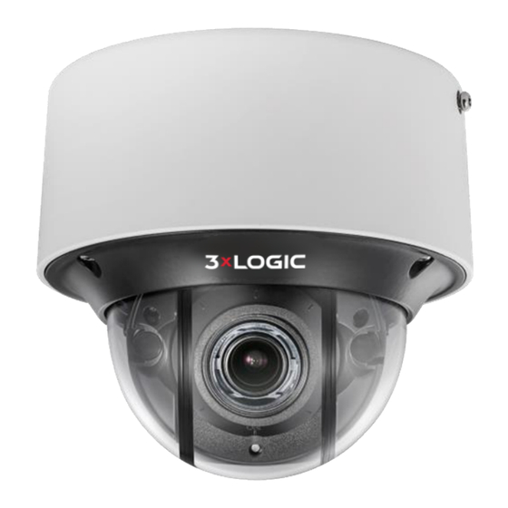
V-Series Camera Quick Start Guide | VX-2V-MD-RIWH 1 Camera Overview Camera components are outlined below: Overview Camera Components (1) Camera Components (2) Description of Camera Components AVAILABLE MOUNTS No. Description No. Description § D2 Wall Mount (3xLOGIC Product #: VX-WM-D2) Mounting base Dome cover § D2 Pendant Mount (3xLOGIC Product #: VX-PM-D2) Lens § D2 Ceiling Flush Mount (3xLOGIC Product #: VX-FM-D2) Water-proof Side outlet § Universal Corner Mount (3xLOGIC Product #: VX-CM) plug cover § Universal Pole Mount (3xLOGIC Product #: VX-POLE) Reset button Serial port Memory card GND slot Note: Press RESET for 10s when the camera is powering on or rebooting to restore the default settings, including the user name, password, IP address, port No., etc. 12000 Pecos St., Suite 290, Westminster, CO 80234 | www.3xlogic.com | (877) 3XLOGIC... -
Page 4: Cables
V-Series Camera Quick Start Guide | VX-2V-MD-RIWH Cables The following figures and tables describe the cables included with this camera. Overview of Cables (1) Description of Cables No. Description HDMI Out (Video Out, Female Connection) 10M/100M self-adaptive Ethernet cable and RJ45 interface (PoE supported) Power supply cable and terminal block interface Installation Before you start: Make sure the device in the package is in good condition and all the assembly parts are included. The standard power supply is 12V DC or 24V AC. Please make sure your power supply is the correct power supply for your camera. Make sure all the related equipment is powered-off during the installation. Check the specification of the products for your chosen installation environment. Make sure that the installation surface is strong enough to withstand four times the weight of the camera and the bracket. For the camera that supports IR, you are required to pay attention to the following precautions to prevent IR reflection: Dust or grease on the dome cover will cause IR reflection. Please do not remove the dome cover film until the installation is finished. If there is dust or grease on the dome cover, clean the dome cover with clean soft cloth and isopropyl alcohol. Make sure that there is no reflective surface too close to the camera lens. The IR light from the camera may reflect back into the lens causing reflection. The foam ring around the lens must be seated flush against the inner surface of the bubble to isolate the lens from the IR LEDS. Fasten the dome cover to camera body so that the foam ring and the dome cover are attached seamlessly. Purpose: Before mounting, you must first disassemble the camera and install the memory card INSTALL PREPARATION - DISASSEMBLING Steps: 1. Loosen the three screws on the edge of the dome cover with the screw driver. 2. Lift and put aside the dome cover to disassemble the camera. 12000 Pecos St., Suite 290, Westminster, CO 80234 | www.3xlogic.com | (877) 3XLOGIC... -
Page 5: Install Preparation - Memory Card Installation
V-Series Camera Quick Start Guide | VX-2V-MD-RIWH Dome Cover Screws Camera Body Remove the Dome Cover INSTALL PREPARATION - MEMORY CARD INSTALLATION Steps: 1. Rotate the camera body to completely expose the memory card slot. 2. Insert the memory card into the memory card slot, and push it in to mount the card. Memory Card Install the Memory Card 3. (Optional) To unmount the memory card, push on the card to eject. INSTALLATION - CEILING MOUNTING 1. Attach the supplied drill template to the location where you want to install the camera. 2. Drill the screw holes and the cable hole according to the drill template as the figure below. 12000 Pecos St., Suite 290, Westminster, CO 80234 | www.3xlogic.com | (877) 3XLOGIC... - Page 6 V-Series Camera Quick Start Guide | VX-2V-MD-RIWH Drill Template The drill template may vary according to different camera models. (Optional) Routing the cable from the side outlet instead of the cable hole drilled on the ceiling Note: is supported. Side Outlet Side Outlet 3. Fix the mounting base to the ceiling with the supplied screws. Ceiling Mounting Base Screws Install the Mounting Base 4. Align the camera body with the mounting base and rotate the camera body counterclockwise to get it fitted with the mounting base. 12000 Pecos St., Suite 290, Westminster, CO 80234 | www.3xlogic.com | (877) 3XLOGIC...
- Page 7 V-Series Camera Quick Start Guide | VX-2V-MD-RIWH Lock Screw Install the Camera Body 5. Connect the video output connector to the monitor and connect the power connector to the power supply to adjust the surveillance angle and image. 6. Adjust the surveillance angle and image according to the figures below. 1). 3-axis Adjustment Tilt: 0° to 75° Pan: 0° to 355° Rotate: 0° to 355° 3-axis Adjustment 7. Zoom and Focus Adjustment: Cameras of this series are equipped with a motor-driven lens. You can adjust the zoom and focus level on PTZ control panel by visiting the camera via web browser or client software. See Section 2 for information on identifying and setting up the camera on your network Please reference the VIGIL Client User Guide or the 3xLOGIc VISIX V-Series Gen II User Manual for information on adjusting zoom and focus from VIGIL Client or from the camera browser interface respectively. Zoom and Focus Adjustment via Web Browser 12000 Pecos St., Suite 290, Westminster, CO 80234 | www.3xlogic.com | (877) 3XLOGIC...
-
Page 8: Installation - Wall Mounting
V-Series Camera Quick Start Guide | VX-2V-MD-RIWH 8. Attach the dome cover to the camera body. Fix it with screwdriver to get tightened as shown in the figures below. Install the Dome Cover 9. Tighten the lock screw to complete the installation. Lock Screw Complete the Installation INSTALLATION - WALL MOUNTING Before you start: A wall mounting bracket is not included in package. If you choose this mounting type, you have to prepare a bracket first. The wall mounting bracket shown below is only for demonstration. Note: When choosing a wall mounting bracket, you must pay attention to the size of the cap which should match the mounting base of the camera. 12000 Pecos St., Suite 290, Westminster, CO 80234 | www.3xlogic.com | (877) 3XLOGIC... - Page 9 V-Series Camera Quick Start Guide | VX-2V-MD-RIWH Size of the Mounting Base Steps: 1. Route the cables, install the wall mounting bracket, and secure the cap on the bracket. Wall Mounting Bracket Install Wall Mounting Bracket 2. Align the screw holes of the mounting base with the corresponding screw holes of the cap. Mounting Base Install the Mounting Base 3. Secure the mounting base to the cap with screws. 4. Align the camera with the mounting base, and secure the camera with screws. 12000 Pecos St., Suite 290, Westminster, CO 80234 | www.3xlogic.com | (877) 3XLOGIC...
-
Page 10: Installation - Pendant Mouting
V-Series Camera Quick Start Guide | VX-2V-MD-RIWH Secure the Camera 5. Connect the video output connector to the monitor and connect the power connector to the power supply to adjust the surveillance angle and image. 6. Adjust the image and focus. 7. Install the dome cover back to the camera and tighten the lock screw to complete the installation. INSTALLATION - PENDANT MOUTING Before you start: The Pendant mounting bracket is not included in package. If you choose this mounting type, you have to prepare a bracket first. The pendant mounting bracket shown below is only for demonstration. Note: When choosing a pendant mounting bracket, you must pay attention to the size of the cap which should match the mounting base of the camera. Size of the Mounting Base Steps: 12000 Pecos St., Suite 290, Westminster, CO 80234 | www.3xlogic.com | (877) 3XLOGIC... - Page 11 V-Series Camera Quick Start Guide | VX-2V-MD-RIWH 1. Route the cables and install the pendant mounting bracket. Secure the cap on the bracket. Pendant Mounting Bracket Install the Pendant Mounting Bracket 2. Align the screw holes of the mounting base with the corresponding screw holes of the cap. Mounting Base Install the Mounting Base 3. Secure the mounting base to the cap with screws. 4. Align the camera with the mounting base, and secure the camera with screws. Secure the Camera 5. Connect the video output connector to the monitor and connect the power connector to the power supply to adjust the surveillance angle and image. 6. Adjust the image and focus. 7. Install the dome cover back to the camera and tighten the lock screw to complete the installation. 12000 Pecos St., Suite 290, Westminster, CO 80234 | www.3xlogic.com | (877) 3XLOGIC...
-
Page 12: (Optional) Installation Of Network Cable Water-Proof Jacket
V-Series Camera Quick Start Guide | VX-2V-MD-RIWH (OPTIONAL) INSTALLATION OF NETWORK CABLE WATER-PROOF JACKET Purpose: If the camera is installed outdoors, you can install a waterproofing jacket for the network cable after the camera is secured to the installation surface. ① ② ④ ③ ⑤ ⑥ ⑦ Water-proof Accessory Components Table 1-2 Components No. Components Camera’s Network Interface Socket O-Type Gasket Network Plug Waterproof Endcap Waterproof Rubber Gasket Lock Nut Network Cable from Router/Switch Steps: 1. Feed the plugless network cable ⑦ through the lock nut ⑥, waterproof rubber gasket ⑤ (the rubber gasket inset ridge must face the waterproof endcap), and the waterproof endcap ④ in order. 2. Crimp an RJ-45 network plug ③onto the end of the cable, taking care to insert the twisted pairs of wires in correct order. 3. Place the O-type gasket ② onto the end of the camera’s network interface socket ①. 4. Insert the network plug ③ into the camera’s network interface socket①. 5. Insert the waterproof rubber gasket ⑤ into the waterproof endcap ④, and secure lock nut ⑥ with the waterproof endcap ④. - Page 13 V-Series Camera Quick Start Guide | VX-2V-MD-RIWH Purpose If the camera is installed outdoors, you can use the supplied water-proof tape to protect cable connectors and unused cables after the camera is secured to the installation surface. Steps: 1. Tear off the yellow release paper on the back of the water-proof tape. 2. Stretch the water-proof tape to reach twice the initial length. Initial Length Stretch Stretch Waterproof Tape Length After Stretching Stretch the Water-proof Tape 3. Wrap the water-proof tape around the cable connector tightly as shown in the figure below. Cable Connector Wrap the Water-proof Tape Note: Make sure that all exposed wires are all firmly wrapped and concealed by the water-proof tape. 4. Press the tape firmly on both ends of the connector to make sure no water can penetrate, as shown in the figure below. Press Press the Water-proof Tape 5. Wrap the water-proof tape around the remaining unused cables tightly as shown in the figure below (some camera models may not feature all the pictured cables). 12000 Pecos St., Suite 290, Westminster, CO 80234 | www.3xlogic.com | (877) 3XLOGIC...
- Page 14 V-Series Camera Quick Start Guide | VX-2V-MD-RIWH Wrap the Water-proof Tape Note: Make sure that all exposed wires are all firmly wrapped and concealed by the water-proof tape. 6. Press the tape firmly to make sure no water can penetrate as shown in the figure below. Press Press the Water-proof Tape 12000 Pecos St., Suite 290, Westminster, CO 80234 | www.3xlogic.com | (877) 3XLOGIC...
-
Page 15: Camera Setup
Follow prompts in the VSX Setup app, and scan the camera’s QR to complete configuration and enrollment. You will be required to activate the camera by assigning a complex password. Be sure to remember the VIGIL Connect Alias as well as the username and password you assign to the camera. These credentials will be required to add the camera to other VIGIL utilities. Ensure that the camera is configured with the proper time zone, auto daylight savings update and set for NTP (auto time sync). The cameras live view will be displayed in the app for final positioning. Setup results can be emailed upon completion for easy monitoring configuration. Note: The V-Series camera will automatically check for updates and format the SD card. Please allow 15 minutes before power cycling the camera. Camera Setup - Non-DHCP Networks The 3xLOGIC All-in-One PC Setup software was engineered specifically for use in non-DHCP networks where the mobile app (requires DHCP) cannot be used to configure the camera. A laptop connected to the same network as the camera will be required to discover the camera and assign a valid IP address using the 3xLOGIC All-in-One PC Setup. Download and install the 3xLOGIC All-in-One PC Setup Utility for Windows from: http://www.3xlogic.com/support-center/software 12000 Pecos St., Suite 290, Westminster, CO 80234 | www.3xlogic.com | (877) 3XLOGIC... - Page 16 V-Series Camera Quick Start Guide | VX-2V-MD-RIWH Confirm the PC is networked with the cameras then launch the utility. If properly networked, the utility will automatically detect cameras on the network (click Refresh to refresh the list). Select the desired device from the list of available cameras. Click IP Setup and assign the desired IP. Fill out installer and company information. To activate the camera, you will be required to assign a complex password. Confirm the camera Live View preview is as desired and click Continue. Adjust any/all camera settings including the camera name and VIGIL Connect alias. Be sure to remember the VIGIL Connect Alias as well as the username and password you assign to the camera. These credentials will be required to add the camera to other VIGIL utilities. Fill out remaining information and complete steps in the setup tool to receive an installation summary e-mail. NOTE: The V-Series camera will automatically check for updates and format the SD card. Please allow 15 minutes before power cycling the camera. 12000 Pecos St., Suite 290, Westminster, CO 80234 | www.3xlogic.com | (877) 3XLOGIC...
-
Page 17: Quick Start
V-Series Camera Quick Start Guide | VX-2V-MD-RIWH 3 Quick Start Quick Start - Enabling HDMI Output in Camera Browser Settings for Public View Monitor Use To utilize the camera’s HDMI output for use with an external monitor, confirm the camera’s Local Output display settings is configured correct. Steps: Navigate to the camera’s web interface login screen. Enter the camera’s IP address into a browser URL field and hit Enter. Fill in the required login credentials and click Login to proceed. Enabling HDMI Output in Browser Settings Navigate to Configuration>Image>Display Settings. Click Other to deploy the Local Output settings menu. Select HDMI_1080P60. 12000 Pecos St., Suite 290, Westminster, CO 80234 | www.3xlogic.com | (877) 3XLOGIC... -
Page 18: Quick Start - Remote Monitoring And Viewing - Adding A V-Series Camera To Vigil Client
V-Series Camera Quick Start Guide | VX-2V-MD-RIWH Quick Start - Remote Monitoring and Viewing - Adding a V-Series Camera to VIGIL Client Steps: To interface a V-Series Camera with VIGIL Client: Launch VIGIL Client (Local Mode only; VCM mode will only display Servers from a networked VCM Server) and select Servers from the Servers top menu. This will launch the Servers window. VISIX V-Series devices are considered edge recording devices and thus are recognized as their own VIGIL Server within the VIGIL suite. Click Add. This will deploy the Add/Edit VIGIL Server window. Enable the Use VIGIL Connect option. If connecting using traditional network connection criteria is desired, enter the cameras IP Address/DNS Name and confirm TCP/IP port status. -
Page 19: Quick Start - Remote Monitoring And Viewing - Adding A V-Series Camera To 3 Xlogic View Lite Ii Mobile
V-Series Camera Quick Start Guide | VX-2V-MD-RIWH Quick Start - Remote Monitoring and Viewing - Adding a V-Series Camera to 3xLOGIC View Lite II Mobile (Android and iOS) Steps: To interface a V-Series camera with 3xLOGIC’s View Lite II mobile app, launch the View Lite II app on your mobile device (Android OS is pictured in the below screenshot, however, the process is identical in the iOS version). Open the Options side menu and select Server Configuration. The Video Source list will display. Opening Video Source Menu Select VIGIL Server. VISIX V-Series devices are considered edge recording devices, and thus are recognized as their own VIGIL Server within View Lite II. The VIGIL Server window will now deploy. A menu of all VIGIL Servers already interfaced with View Lite II will be visible. : Adding a Video Source - Add Video Source To add a new instance of a video source, tap the icon. Enable VIGIL Connect. Alternatively, if you wish to use traditional network connection criteria, leave VIGIL Connect disabled and enter in an IP/DNS Name and Port info (if using standard network connection criteria, also ignore step 6 of these instructions) for the device. Enter in the VIGIL Connect alias for the desired VISIX V-Series camera (VSeriescam1 used in the above example). View Lite II - Add/Edit Server Form - Android Fill in the remaining required fields and tap Save to save the V-Series camera to View Lite II. A user may now add the camera stream to the View Lite viewer using the same process as adding VIGIL Server, VCM or 3xCLOUD networked cameras. 12000 Pecos St., Suite 290, Westminster, CO 80234 | www.3xlogic.com | (877) 3XLOGIC... - Page 20 12000 Pecos St., Suite 290 Westminster, CO 80234 303.430.1969 Toll Free: 877.3xLOGIC www.3xlogic.com © 2018 3xLOGIC Inc. All rights reserved. Information in this document is subject to change without notice. 3xLOGIC and the 3xLOGIC logo are trademarks of 3xLOGIC, Inc. all other trademarks are property of their respective owners. Revised: February 12, 2018...
Need help?
Do you have a question about the VX-2V-MD-RIWH and is the answer not in the manual?
Questions and answers