Omron V530-R160E User Manual
2d code reader
Hide thumbs
Also See for V530-R160E:
- Specifications (7 pages) ,
- Datasheet (6 pages) ,
- Instruction (7 pages)
Table of Contents
Advertisement
Quick Links
Download this manual
See also:
Instructions
Advertisement
Table of Contents
Troubleshooting

Related Manuals for Omron V530-R160E


Summary of Contents for Omron V530-R160E
- Page 1 2D Code Reader V530-R160E/V530-R160EP USER'S MANUAL Cat. No. Z169-E1-04...
- Page 2 Product Availability Some of the products listed may not be available in some countries. Please contact your nearest OMRON sales office by referring to the addresses provided at the back of this manual. © OMRON, 2002 All rights reserved. No part of this publication may be reproduced, stored in a retrieval system, or transmitted, in any form, or by any means, mechanical, electronic, photocopying, recording, or otherwise, without the prior written permission of OMRON.
-
Page 3: Introduction
SECTION 3 Connection to the Host SECTION 4 Basic Operations SECTION 5 Setting Reading Conditions SECTION 6 Other Functions System Settings SECTION 7 Communication with the Host SECTION 8 Troubleshooting SECTION 9 Appendix SECTION10 V530-R160E/V530-R160EP 2D Code Reader User's Manual... -
Page 4: Application Considerations
PRODUCTS, WHETHER SUCH CLAIM IS BASED ON CONTRACT, WARRANTY, NEGLIGENCE, OR STRICT LIABILITY. In no event shall responsibility of OMRON for any act exceed the individual price of the product on which liability is asserted. IN NO EVENT SHALL OMRON BE RESPONSIBLE FOR WARRANTY, REPAIR, OR OTHER CLAIMS REGARDING THE PRODUCTS UNLESS OMRON’S ANALYSIS CONFIRMS THAT THE PRODUCTS... - Page 5 UPON AS A SAFETY COMPONENT OR PROTECTIVE DEVICE FOR SUCH PURPOSES. Please refer to separate catalogs for OMRON’s safety rated products. OMRON shall not be responsible for conformity with any standards, codes, or regulations that apply to the combination of products in the customer’s application or use of the product.
- Page 6 Performance data given in this document is provided as a guide for the user in determining suitability and does not constitute a warranty. It may represent the result of OMRON’s test conditions, and the users must correlate it to actual application requirements. Actual performance is subject to the OMRON Warranty and Limitations of Liability.
-
Page 7: Precautions On Safety
INTRODUCTION PRECAUTIONS ON SAFETY • Meanings of Signal Words The following signal words are used in this manual. Indicates a potentially hazardous situation which, if not avoided, will result in minor or moderate injury, or may result in serious injury or death. Additionally there may be WARNING significant property damage. -
Page 8: Precautions For Safe Use
This product is not designed or rated for ensuring safety of persons. Do not use it for such purposes. A lithium battery is built into the V530-R160E/EP and may occasionally combust, explode, or burn if not treated properly. Dispose of the Controller as industrial waste, and never disassemble, apply pressure that would deform, heat to 100 C or higher, or incinerate the V530-R160E/EP. - Page 9 • Use an appropriate ground (100 Ω maximum). • Use a grounding point as close as possible to the V530-R160E/EP and keep the ground line as short as possible. • Wire the V530-R160E/EP to the ground with a separate ground wire. To avoid grounding problems, do not share the ground wiring with any other devices or ground the V530-R160E/EP to the building’s steel framing or plumbing.
-
Page 10: Precautions For Correct Use
Notice for Korea Radio Law Other Precautions • Do not attempt to disassemble, repair, or modify the V530-R160E/EP. Doing so may cause product failure or a fire. • If you suspect an error or malfunction, stop using the V530-R160E/EP immediately, turn OFF the power supply, and consult your OMRON representative. -
Page 11: Controller Installation Site
INTRODUCTION Controller Installation Site Do NOT install the V530-R160 in locations subject to the following condi- tions: • Ambient temperatures outside of 0 to +50°C (32 to 122°F) range • Rapid temperature fluctuations (likely to cause condensation) • Relative humidities outside of the 35 to 85% range •... -
Page 12: Component Installation And Handling
200 mm min. 200 mm min. V530-R160 Component Installation and Handling OMRON Components Be sure to use the Camera, Camera Cable, and Console designed for the V530-R160. Refer to page 36. Cameras and Cables Always turn OFF the power before connecting or disconnecting cameras or cables. - Page 13 INTRODUCTION Touching Signal Lines To prevent damage from static electricity, use a wrist strap or another device for preventing elec- trostatic discharges when touching terminals or signal lines in connectors. Removing the Memory Card Before removing a Memory Card, stop the power supply to the Card or turn OFF the V530-R160. The Memory Card or the V530-R160 itself may be damaged if a Memory Card is removed while power is being supplied.
-
Page 14: Confirming Package Contents
INTRODUCTION Confirming Package Contents Check the contents of the package as soon as you receive the V530-R160. Contact the nearest OMRON representative if any of the following items are missing. • V530-R160 2-Dimensional Code Reader Controller V 53 0- PO W... - Page 15 INTRODUCTION • Ferrite Core for F150-VM-2D Monitor Cable: Qty: 1 • User's Manual (this manual) 2D Code Reader V530-R160E/V530-R160EP USER'S MANUAL Cat. No. Z169-E1-01 V530-R160 Operation Manual...
-
Page 16: Editor's Note
INTRODUCTION Editor's Note Visual Aids The following headings appear in the left column of the manual to help you locate different types of information. Indicates information required to take full advantage of the functions and performance of the product. Incorrect application methods may result in the loss of damage or damage to the product. - Page 17 INTRODUCTION MEMO V530-R160 Operation Manual...
-
Page 18: Table Of Contents
INTRODUCTION Table of Contents Introduction APPLICATION CONSIDERATIONS PRECAUTIONS ON SAFETY Precautions for Safe Use Precautions for Correct Use Controller Installation Site Component Installation and Handling Confirming Package Contents Editor's Note Visual Aids Table of Contents Searching from the Menu Tree SECTION 1 Outline What is a 2-dimensional Code Reader? Introduction to Functions... - Page 19 INTRODUCTION Connecting a Camera Power Supply and Ground Crimp Terminals and Cables Ground Wiring Wiring the Power Supply Cameras, Lenses, Lighting, and Memory Cards Overview of Available Cameras CCTV Lenses Lighting Memory Card SECTION 3 Connection to the Host Connecting through the Parallel I/O I/O Terminal Connections I/O Connector Connections Internal Specifications...
- Page 20 INTRODUCTION Entering the SET Mode Selecting Shutter Speed Registering Models of Finder Pattern Perform Tests Start Reading Save Settings and Exit the V530-R160 SECTION 5 Setting Reading Conditions Adjusting the Image (Image Adjust) Switching Cameras Shutter Speed Filtering Filtering Retry BGS Levels Light Control Setting Reading Conditions (DataMatrix)
- Page 21 INTRODUCTION Backing Up Data Backing Up to Flash Memory Backing Up Data to a Computer Backing Up Data to a Memory Card Memory Card Operations Creating Directories Copying Files Checking File Properties Changing File Names Deleting Files and Directories Turning OFF the Power Supply to the Memory Card Checking I/O Status with Host Devices (I/O Monitor) Serial Interface Parallel I/O Interface...
- Page 22 INTRODUCTION Command List I/O Format Command Format Connection Examples for Programmable Controller (Normal) Serial Interface (Host Link) Flow Charts Setting Communications Specifications I/O Format Connection Examples for Programmable Controller (Host Link)244 SECTION 9 Troubleshooting Improving Reading Environment and Setup Conditions Settings Countermeasure Examples Error Codes and Countermeasures Error Messages and Corresponding Corrective Actions...
- Page 23 INTRODUCTION Console F150-KP-2D Camera Cable (For F150-S1A-2D Camera) F150-VS-2D Monitor Cable F150-VM-2D Parallel I/O Cable F160-VP LCD Color Monitor F150-M05L-2D Memory Card F160-N64S(S) QM300-N128S ASCII Codes FCS Check Program Examples (BASIC) Data Capacity Tables Glossary Index Revision History V530-R160 Operation Manual...
-
Page 24: Searching From The Menu Tree
INTRODUCTION Searching from the Menu Tree p.144 p.104 Camera 0 DataMatrix 0. Image Adjust Select camera p.93 Camera 1 1/100s Shutter speed 1/500s p.94 1/2000s 1/10000s Filtering Weak smoothing Strong smoothing p.95 Dilate Erosion Median Filt. 1 Filtering retry Filt. 2 p.97 Filt. - Page 25 INTRODUCTION p.71 p.71 Intelli. Light 0 Camera/Monitor Intelli. Light 1 p.181 Monitor Character color BG color Communication RS-232C/422 Interface Baud rate Data length Parity bits Stop bits p.207 Header Footer Mode Transfer protocol Flow control p.208 Normal Timeout Read area Host link Begin read word p.238...
- Page 26 INTRODUCTION TOOL Load (Serial) System data Save (Serial) p.149 Load (Memory card) Save (Memory card) Scene data Same as for "System data" Same as for "System data" System + Scene data Image data Load (Serial) Save (Serial) Load (Memory card) Save (Memory card) p.149 Load 00-35...
-
Page 27: Section 1 Outline
SECTION 1 Outline This section introduces the functions and operational flow of the controller. What is a 2-dimensional Code Reader? Introduction to Functions Operational Flow V530-R160 Operation Manual... -
Page 28: What Is A 2-Dimensional Code Reader
SECTION 1 Outline What is a 2-dimensional Code Reader? It is a device for reading 2-dimensional codes directly marked on products and parts. 2-dimensional code means code that has two dimensions (faces). It permits more data to be written than bar code, which contains information in one direction only. - Page 29 SECTION 1 Outline The Marking can be Done in a Small Space Conventional bar codes were too large to be printed on some smaller parts. 2-dimensional codes allow high-density information to be packed into a small space. Example: Reading printed circuit board information. V530-R160 Operation Manual...
-
Page 30: Introduction To Functions
SECTION 1 Outline Introduction to Functions Reading is possible for both DataMatrix and QRCode. Reading code DataMatrix QRCode (Model 1, 2) 21 × 21 to 41 × 41 Corresponding size •ECC200 (Matrix size) 10 × 10 to 64 × 64 (Version 1 to 6) 8 ×... - Page 31 SECTION 1 Outline 2 cameras can be used for reading. If two cameras are connected, two types of reading process can be handled with one controller. The scene can be set for each process, and the reading triggers can be input at TRIG C and TRIG D of the parallel I/O.
- Page 32 SECTION 1 Outline Dot code images can be converted to easy-to-read images. Dilate or Erosion processing converts code images that have a small dot size and are difficult to read into images that can be read reliably. Refer to page 94 (Sec.5). Result of Dilate Before processing After processing...
- Page 33 SECTION 1 Outline The reading results over time can be expressed in the form of a graph. By using the trend monitor display function, trends in the marking status and illumination status of the code can be observed. This can help prevent the occurrence of frequent reading failures, and help in the analysis of the cause of reading failures.
-
Page 34: Operational Flow
SECTION 1 Outline Operational Flow Installation Refer to page 36. SECTION 2 Installation and Connections Connecting the Host Refer to page 53. SECTION 3 Connection to the Host Turn ON the power supply. Selecting the Menu Corresponding to the Code DataMatrix Refer to page 76 (Sec.4). - Page 35 SECTION 1 Outline Changing Reading Conditions Saving Reading Conditions Refer to page 112 (Sec.5). Refer to page 90 (Sec.4). Setting Reading Conditions (DataMatrix) step 5. Save Settings and (Setting Reading Conditions) Exit the V530-R160 Changing Items Displayed on the Monitor Refer to page 114 (Sec.5).
- Page 36 SECTION 1 Outline MEMO V530-R160 Operation Manual...
-
Page 37: Section 2 Installation And Connections
SECTION 2 Installation and Connections This section explains how to install the Controller and connect the peripheral devices. Basic System Configuration Component Names and Functions Mounting the Controller Connecting Peripheral Devices Power Supply and Ground Cameras, Lenses, Lighting, and Memory Cards V530-R160 Operation Manual... -
Page 38: Basic System Configuration
Camera cable F150-VS-2D (3 m) CAMERA1 p.45 Power supply The power supply is capped in place to protect against electric shock while the MONITOR V530-R160 is shipped. Monitor cable 24VDC F150-VM-2D (2 m) Recommended model: OMRON S8VS-06024 V530-R160 Operation Manual... - Page 39 SECTION 2 Installation and Connections Camera This is the part that captures an image of the object. Up to 2 cameras can be connected to a V530-R160. Camera Only A standard CCTV lens and light will be needed. F150-S1A-2D Camera with an Intelligent Lighting F150-SLC20 (20 mm field of vision) Monitor The Monitor is used to check the image and display menus...
-
Page 40: Component Names And Functions
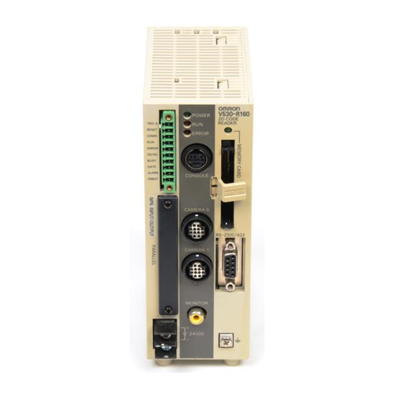
SECTION 2 Installation and Connections Component Names and Functions 15. Console connector 14. Memory Card indicator 1. POWER indicator 2. RUN indicator 3. ERROR indicator 13. Memory Card slot V 5 3 0 P O W - R 1 6 2 D C O D E R E A... -
Page 41: Mounting The Controller
“bottom surface-mounting”. DIN Track Mounting The 2-Dimensional Code Reader can be easily mounted to or removed from 35-mm DIN Track. TRIG-A ALARM DIN Track (OMRON) PFP-100N (1 m) PFP-50N (50 cm) PFP-100N2 (1 m) PFP-M End Plate (OMRON) ... -
Page 42: Rear Surface-Mounting
SECTION 2 Installation and Connections Rear Surface-mounting Attach the Mounting bracket to the V530-R160 Controller using the four machine screws (M3 × 6) included with the bracket. V 5 3 0 P O W -R 1 6 2D C O D E R E A R U N D E R... -
Page 43: Side Surface-Mounting
SECTION 2 Installation and Connections Side Surface-mounting V 5 3 0 P O W -R 1 6 2D C O D E R E A R U N D E R E R R C O N S O L E C A M E R A C A M... -
Page 44: Bottom Surface-Mounting
SECTION 2 Installation and Connections Bottom Surface-mounting V 5 3 0 P O W -R 1 6 2D C O D E R E A R U N D E R E R R C O N S O L E C A M E R A C A M... -
Page 45: Connecting Peripheral Devices
SECTION 2 Installation and Connections Connecting Peripheral Devices This section shows how to connect peripheral devices to the V530-R160. • Turn OFF the power to the V530-R160 before connecting or disconnecting cables. Peripheral devices can be damaged if connected or disconnected with the power supply turned ON. •... -
Page 46: Power Supply And Ground
SECTION 2 Installation and Connections Power Supply and Ground Wire the power supply and the ground to the top terminal block, and tighten the screws to a torque of N·m. 0.49 After wiring, check to make sure that the wiring is correct. Crimp Terminals and Cables The terminal block uses M3 terminal screws. -
Page 47: Wiring The Power Supply
Manufacturer Model voltage 1.6 A min. 20.4 to 26.4 VDC OMRON S8VS-06024 Use a DC power supply with safe extra low-voltage circuits on the secondary side. If UL recognition is required, use a UL class II power supply. V530-R160 24VDC 24 VDC Keep the power supply cable as short as possible (10 m max.). -
Page 48: Cameras, Lenses, Lighting, And Memory Cards
SECTION 2 Installation and Connections Cameras, Lenses, Lighting, and Memory Cards This section provides additional information on cameras, CCTV lenses, lighting, and Memory Cards. Overview of Available Cameras The F150-SLC20 Camera with Intelligent Lighting is a camera dedicated to the V530-R160 and has a special lens and light already fitted. -
Page 49: Cctv Lenses
SECTION 2 Installation and Connections CCTV Lenses When using a Camera without a light (F150-S1A-2D), refer to the following graph to select the appropriate Lens and Extension Tube. The lens required will differ depending on the size of the object and the distance to the lens (WD). ... - Page 50 SECTION 2 Installation and Connections Lenses and Lens Diameters 1"-32UN Max. outer dia. 30 dia. Total length Lenses and Lens Diameters Focus Maximum outer Total Lens Brightness Filter size length diameter length 3Z4S-LE C418DX 4.8 mm F1.8 40.5 mm dia. 35.5 mm −...
-
Page 51: Lighting
SECTION 2 Installation and Connections Lighting A stable image must be obtained to ensure accurate inspection. Use appropriate lighting for the application and the measurement object if using a Camera without a light (F150-S1A-2D). Selecting a Light View the object from the front. Seen from the front, does the code contrast clearly Ring Lights... - Page 52 SECTION 2 Installation and Connections Lighting Back Lighting Reflected Lighting Ring Lights A stable, high-contrast image can be obtained using back lighting. Objects can be illuminated uniformly. Camera Camera Light source Object Object Light source Applications: Reading codes on transparent Applications: Printed markings on paper labels objects such as sheet glass and cardboard, stamped markings...
-
Page 53: Memory Card
Memory Card into the computer and copying the desired data. Recommended Model Manufacturer Model Capacity OMRON F160-N64S(S) 64 MB OMRON QM300-N128S 128 MB A filler card with no memory is inserted into the V530-R160's Memory Card slot when the V530- R160 is shipped. - Page 54 (PCMCIA2.0/JEIDA4.1 or higher, type II compatible) or Compact Flash TM drive. The Memory Card must be inserted into a PC Card Adapter in order to be used in a PC Card drive. Recommended Model Name Manufacturer Model PC Card PC Card Adapter OMRON HMC-AP001 Adapter V530-R160 Operation Manual...
-
Page 55: Section 3 Connection To The Host
SECTION 3 Connection to the Host This section describes how to connect host devices through a parallel I/O or serial interface. Connecting through the Parallel I/O Connecting through the Serial Interface V530-R160 Operation Manual... -
Page 56: Connecting Through The Parallel I/O
SECTION 3 Connection to the Host Connecting through the Parallel I/O This section explains how to connect inputs and outputs to the V530-R160 through its parallel I/O to input signals such as reading triggers, or output signals such as reading judgements (OK/NG). Either the “I/O terminals”... - Page 57 SECTION 3 Connection to the Host Use a flat-blade precision screwdriver to loosen the connec- tor's set screw. Counter-clockwise Insert the signal wire. Tighten the set screw to secure the wire. Tighten to a N·m torque of 0.22 to 0.25 Clockwise Insert the connector into the V530-R160.
-
Page 58: I/O Connector Connections
SECTION 3 Connection to the Host I/O Connector Connections Use a F160-VP Parallel I/O Cable (order separately) to connect to the V530-R160's I/O connec- tor. Align the connectors and insert the cable's connector straight into the V530-R160's I/O con- nector. Tighten the connector's mounting screws to secure the connection. V530-R160 F160-VP Parallel I/O Cable (2 m) RS-232C/422... - Page 59 SECTION 3 Connection to the Host Wire Marking Wire Marking Signal Function Signal Function color (Black) color (Red) RESET Light Restarts the COMIN Light Common for brown V530-R160. brown input signals TRIG A Yellow Trigger input Yellow Do not use. (One shot reading) TRIG B...
-
Page 60: Internal Specifications
Double-check the connector wiring for mistakes before turning ON the power supply for the first time. Internal Specifications Input Specifications Item Specification Model V530-R160E (NPN mode) V530-R160EP (PNP mode) 12 to 24 VDC ± 10% Input voltage ON current 3 to 15 mA ON voltage 8.8 V max. - Page 61 SECTION 3 Connection to the Host Output Specifications Item Specification Model V530-R160E (NPN mode) V530-R160EP (PNP mode) Output voltage 12 to 24 VDC ± 10% Load current 45 mA max. ON residual voltage 2 V max. OFF leakage current 0.1 mA max.
-
Page 62: Connecting Through The Serial Interface
SECTION 3 Connection to the Host Connecting through the Serial Interface The V530-R160's serial interface (RS-232C/RS-422 connector) can be used to connect input signals such as reading triggers or output signals such as reading judgements. Additionally, data that has been set in the V530-R160 can be backed up in a personal computer. -
Page 63: Connector
Not connected RDB(RD+) RS-422 RDA( RD- ) RS-422 SDB(SD+) RS-422 RS-422 SDA( SD- ) Signal ground RS-422 Block Diagram SDB(SD+) SDA(SD-) RDB(RD+) RDA(RD-) Use a compatible connector. Recommended Model Manufacturer Model Plug OMRON XM2A-0901 Hood OMRON XM2S-0911 V530-R160 Operation Manual... -
Page 64: Connection Examples
SECTION 3 Connection to the Host Connection Examples 1:1 Connection (Personal Computer) V530-R160 RS-232C cable XW2Z-200S-V (2 m) XW2Z-500S-V (5 m) V530-R160 Personal computer Cable Wiring (XW2Z-200S-V/XW2Z-500S-V) The maximum cable length is 15 m. V530-R160 Personal computer Signal Signal RDB(RD+) −... - Page 65 SECTION 3 Connection to the Host 1:1 Connection (Programmable Controller) V530-R160 RS-232C cable XW2Z-200T (2 m) XW2Z-500T (5 m) Programmable Controller V530-R160 CPU Unit: CS1H-CPU** Power Supply Unit: C200H-PA** CQM1H-CPU** CPU Unit: Power Supply Unit: CQM1-PA** RS-232C Cable Wiring (XW2Z-200T/XW2Z-500T) The maximum cable length is 15 m.
- Page 66 NT-AL001 recommended RS-422 cable (Cable wiring 2) RS-422 cable (Cable wiring 2) Branching Link Adapter Branching Link Adapter Branching Link Adapter OMRON B500-AL001 RS-422 cable recommended (Cable wiring 2) Notes: When using B500-AL001, V530-R160 V530-R160 V530-R160 Please set the terminator to "ON", and terminate to the...
- Page 67 SECTION 3 Connection to the Host Cable Wiring 2 (RS-422 (Connection between a Controller and Branching Link Adapter, or between Branching Link Adapter)) Use an AWG22 shielded cable or equivalent. For SDB and SDA, and RDB and RDA, use twisted pair cables. NT-AL001 V530-R160 B500-AL001...
-
Page 68: Connection
SECTION 3 Connection to the Host Connection Align the connectors and insert the cable's connector straight into the V530-R160's I/O connec- tor. Tighten the connector's mounting screws to secure the connection. V530-R160 • Turn OFF the power to the V530-R160 before connecting or disconnecting cables. Peripheral devices can be damaged if connected or disconnected with the power supply turned ON. -
Page 69: Section 4 Basic Operations
SECTION 4 Basic Operations This section describes the basic menu operations. Starting the Controller Basic Knowledge of Operations Understanding Setting Operations step Select the Code and Capture the Image step Set Reading Conditions step Perform Tests step Start Reading step Save Settings and Exit the V530-R160 V530-R160 Operation Manual... -
Page 70: Starting The Controller
SECTION 4 Basic Operations Starting the Controller Enter the controller's menu. Be sure that the basic system components have been connected correctly. Refer to page 36 (Sec.2). TRIG Console V530-R160 VISION MATE CONTROLLER SHIFT CONSOLE Camera Power supply POWER Monitor SYNC Turn ON the power supply on the monitor. - Page 71 SECTION 4 Basic Operations Select the monitor type to be connected. When connecting a color monitor, select Character color and BG color. Select End. The main screen will be displayed. When the settings have been completed, it is useful to use Startup Mode when actually operating the V530-R160.
-
Page 72: Basic Knowledge Of Operations
SECTION 4 Basic Operations Basic Knowledge of Operations Input Devices Menu operations are performed on the Console. The basic functions of the Console keys are as follows. TRIG (trigger) Key TRIG ESC (escape) Key ENT (enter) Key Up, Down, Left, and Right Keys SHIFT F150-KP SHIFT Key... -
Page 73: Screen Displays
SECTION 4 Basic Operations Screen Displays Basic Screen Configuration Mode (See note 1.) Scene Number The current mode is displayed. There are 10 scenes. Setting different measurement condi- tions for each one allows easy switching between different set- ups. The type of image being dis- played is shown. - Page 74 SECTION 4 Basic Operations Note 2: Display Image Display Description Freeze A still image immediately after reading is displayed. The memory number (0 to 35) under which the image is stored is displayed in . When reading moving objects, display freeze images. Through The image currently caught by the Camera is displayed.
-
Page 75: Changing Options
SECTION 4 Basic Operations Changing Options Items with an inverted triangle after them have a list of alternatives. The method for selecting the alternatives is given here. The explanation given here uses the Camera/Monitor system setting as an example. Refer to page 181 (Sec.7). Move the cursor to the item to be selected. -
Page 76: Inputting Values
SECTION 4 Basic Operations Inputting Values This section explains how to input values when setting reading conditions or communications specifications. The explanation given here uses the Date/Time system setting as an example. Refer to page 188 (Sec.7). Move the cursor to the item whose value is to be changed. -
Page 77: Inputting Characters
SECTION 4 Basic Operations Inputting Characters This section explains how to input characters in file names, comments etc. The software keyboard shown below is displayed on the screen where characters are input. These characters can be input. Insert a space. Deletes 1 character to the right of the I cursor. -
Page 78: Understanding Setting Operations
SECTION 4 Basic Operations Understanding Setting Operations This section explains how to set reading conditions using Menus and the basic steps before starting readings. Select the Code and Capture the Image step Move the cursor to MON (monitor) using the Right Key and press the ENT Key. - Page 79 SECTION 4 Basic Operations The setting items will be displayed. To change the code to be read, press the SHIFT + ESC Keys. The screen in will return. Press the ESC Key. The image read from the camera will be displayed. Check that the code of the reading object is displayed on the screen.
- Page 80 SECTION 4 Basic Operations When using an F150-S1A-2D Camera Adjust the focus by turning the focusing ring of the CCTV Lens. Change the shutter speed when the object is moving quickly, causing the image to blur. Refer to page 93 (Sec.5). When using a Camera with an Intelligent Lighting Since the lens has a fixed focal point, adjust the position of the camera by referring to the setting distance information in SECTION 2 Installation and Connections in order to focus it.
-
Page 81: Set Reading Conditions
SECTION 4 Basic Operations Set Reading Conditions step This section explains how to set the basic functions required for reading. There are many other functions apart from these: for details, see SECTION 5 Setting Reading Conditions. Refer to page 91 (Sec.5). Entering the SET Mode Move the cursor to MON (monitor) and press the ENT Key. -
Page 82: Selecting Shutter Speed
SECTION 4 Basic Operations Selecting Shutter Speed Select 0. Image Adjust. The Image Adjust selections will be displayed. Select Shutter speed. The Shutter speed selections will be displayed. Select the shutter speed according to the light level of the image. Press the ENT Key. -
Page 83: Registering Models Of Finder Pattern
SECTION 4 Basic Operations Registering Models of Finder Pattern Register an image of the finder pattern (the L-shape described by 3 of the corners) as the model. Use the teaching function for registration. Using the teaching function, a reading image is obtained, measurement is performed on this image, and based on the results of this measure- ment, parameters for reading conditions (symbol color, Right &... - Page 84 SECTION 4 Basic Operations Select 1. Read DataMatrix. To change the code to be read, press SHIFT+ ESC Keys. The initial screen for the DataMatrix reading will be displayed. Select Pattern settings. The Pattern list will be displayed. Select the pattern number to be registered. Up/Down/Left/Right Keys: To move among pat- tern numbers.
- Page 85 SECTION 4 Basic Operations The Pattern registration screen will be displayed. Select the image to be registered by pressing the SHIFT + Up or Down Keys. Press the ENT Key to validate the setting. The Matrix Size selections will be displayed. Select the Matrix Size.
- Page 86 SECTION 4 Basic Operations What is a pixel? Refer to page 283 (Sec.10). What is a cell? Refer to page 284 (Sec.10). Press the ENT Key to validate the setting. Specify the second end point and the third end point so that they fit the shape of the code. First end point Second end point Third end point...
- Page 87 SECTION 4 Basic Operations The selections for the permissible angle range will be dis- played. Select the range of inclination for the code, and press the ENT Key. Example: Selecting ±45 when the direction of the code is 0° Set a range of inclination of -45° to 45°. Since widening the angle increases the time it takes to read the code, set a range that is not too large but is sufficient.
- Page 88 SECTION 4 Basic Operations The Monitor mode screen will return. Press the TRIG Key to perform teaching. If the result of teaching is OK, the Symbol color, Right & Left reverse, and Matrix Size information is displayed and the pattern is registered. Repeat these steps to register multiple patterns.
-
Page 89: Perform Tests
SECTION 4 Basic Operations Perform Tests step Perform the reading under the conditions that have been previously set. Adjust the reading conditions by referring to the result of the test. When a test is performed in the MON (monitor) mode, the test is completed internally by the V530-R160 and the reading judgements are not output to the host. -
Page 90: Start Reading
SECTION 4 Basic Operations Start Reading step Enter the RUN mode to perform readings. Reading judgements can be output to host devices via the serial interface. For line operation, use this RUN mode. Move the cursor to MON (monitor) and press the ENT Key. - Page 91 SECTION 4 Basic Operations Various commands can be input from a host device in addition to the trigger input. Via the parallel I/O Refer to page 194 (Sec.8). Via the serial interface port using Normal communications Refer to page 212 (Sec.8). Via the serial interface port using Host Link communications Refer to page 240 (Sec.8).
-
Page 92: Save Settings And Exit The
SECTION 4 Basic Operations Save Settings and Exit the V530-R160 step Be sure to save the revised setting data to flash memory before turning OFF. As the V530-R160 loads data from flash memory at startup, any new data will be lost if it is not saved to flash memory. -
Page 93: Section 5 Setting Reading Conditions
SECTION 5 Setting Reading Conditions Set the conditions for reading the code. This section explains how to adjust the image so that the code is caught clearly by the Camera, and the method for setting the Data- Matrix and QRCode reading conditions. Adjusting the Image (Image Adjust) Setting Reading Conditions (DataMatrix) Setting Reading Conditions (QRCode) -
Page 94: Adjusting The Image (Image Adjust)
SECTION 5 Setting Reading Conditions Adjusting the Image (Image Adjust) To ensure accurate and efficient reading, adjust the image so that the code is caught clearly by the Camera. Within the same scene, even if the code reading settings (Read DataMatrix, Read QRCode) are changed, the settings relating to image input are retained. -
Page 95: Shutter Speed
SECTION 5 Setting Reading Conditions The Camera selections will be displayed. Select Camera 0 or Camera 1. Press the ENT Key. The setting will be registered and the screen in will return. Shutter Speed If the image is unsteady, adjust the shutter speed. Speed of the object Shutter speed... -
Page 96: Filtering
SECTION 5 Setting Reading Conditions The Shutter speed selections will be displayed. Select an appropriate speed while viewing the image. Press the ENT Key. The setting will be registered and the screen in will return. Filtering The image read by the Camera can be manipulated to create an image that is easier to read by using the 5 filtering methods. - Page 97 SECTION 5 Setting Reading Conditions Filter size Enables selection of the strength of the processing when an image is manipulated. Example: Effect of changing the filter size when executing Erosion SHIFT + ENT × × Weak Strong Select 0. Image Adjust/Filtering. The Filtering selections will be displayed.
-
Page 98: Filtering Retry
SECTION 5 Setting Reading Conditions Filtering Retry After Filtering, it is possible to add up to four more filtering steps (filter 1 to filter 4). These adjustments can enable more stable reading of the image. The controller executes the process- ing in order from filter 1. - Page 99 SECTION 5 Setting Reading Conditions The setting screen for Filtering retry will be dis- played. Select the filtering method for Filt.1. Press the ENT Key. The filtering method will be saved. Set the filtering methods for Filt.2 to Filt.4 according to your requirements, and then press the ENT Key.
-
Page 100: Bgs Levels
SECTION 5 Setting Reading Conditions BGS Levels This function suppresses the object's background to stabilize reading, eliminating noise and other disturbances. Set the upper and lower limits of the BGS density while monitoring the image. Densities lower than the set lower limit will be converted to 0 (i.e., areas with densities lower than that value will not be read), densities higher than the set upper limit will be converted to 255, and intermediate densities will be graded between 0 and 255. - Page 101 SECTION 5 Setting Reading Conditions The BGS levels setting screen will be displayed. Move the cursor to the upper value and use the Left and Right Keys to adjust the value. Right Key: To increase the lowest digit by one. SHIFT + Right Keys: To increase the value 10 times faster.
-
Page 102: Light Control
SECTION 5 Setting Reading Conditions Light Control When a Camera with an Intelligent Lighting is connected, the light level can be adjusted from the V530-R160. Change the settings in the SYS/Camera/Monitor settings menu in advance to indi- cate that a Camera with an Intelligent Lighting is being used. Refer to page 181 (Sec. - Page 103 SECTION 5 Setting Reading Conditions Light Control Screen B. Light volume A. Segment display C. Sample lighting pattern number A. Segment display Lighting can be adjusted in 5 areas. As viewed from 5 Areas this perspective The reading points are displayed with thick lines. The brightness depends on the set light level. Refer to page 102.
- Page 104 SECTION 5 Setting Reading Conditions Method 1: Using a Sample Lighting Pattern There are 15 sample lighting patterns registered, so the lighting pattern can be selected just by switching through the pattern numbers and determining which pattern gives the sharpest image. The sample pattern number can be switched by pressing the SHIFT Key together with the Left or Right Key.
- Page 105 SECTION 5 Setting Reading Conditions Select 0. Image Adjust/Light control. The setting screen for Light control will be displayed. Switch the sample lighting pattern number using the SHIFT + Left/Right Keys. For fine adjustment of light levels, move to the desired digit using the Right and Left Keys and adjust the light level using the Up and Down Keys.
-
Page 106: Setting Reading Conditions (Datamatrix)
SECTION 5 Setting Reading Conditions Setting Reading Conditions (DataMatrix) Set the reading conditions to suit the code of the reading object. The explanation here deals with the settings for DataMatrix. Pattern Settings A finder pattern image is registered in advance, then when reading is executed a search is con- ducted for an image pattern similar to the input image in order to locate the code. - Page 107 SECTION 5 Setting Reading Conditions Pattern Registration The finder pattern image is registered as a pattern. Up to ten patterns can be registered for one scene, and Code Settings and Search Region are set for each of these patterns. Registering multiple patterns enables reliable reading even if there is dispersion in the dot spacing and printing quality.
- Page 108 SECTION 5 Setting Reading Conditions The following setting information for pattern registration is displayed on the Pattern list screen. Pattern setting information Item Description Pattern Selected pattern number Matrix size Matrix size Color Symbol color of the pattern R&L rev. Execution/non-execution of pattern Right &...
- Page 109 SECTION 5 Setting Reading Conditions To delete a pattern Select the pattern number of the pattern that you want to delete from the Pattern list screen. Up/Down/Left/Right Keys: To move among pat- tern numbers. The selected pattern number is indicated with a solid-line frame.
- Page 110 SECTION 5 Setting Reading Conditions Code Settings Set the conditions to apply in pattern searches. Set the symbol color of the pattern being registered. During teaching, the judged symbol color is automatically set here. (Black*, white) (See note 1.) What is Black &...
- Page 111 SECTION 5 Setting Reading Conditions Select the pattern number of the pattern that you want to set on the Pattern list screen. Up/Down/Left/Right Keys: To move among pat- tern numbers. The selected pattern number is indicated with a solid-line frame. Press the ENT Key.
- Page 112 SECTION 5 Setting Reading Conditions Reference Pattern The registered pattern is displayed on the monitor screen and can be checked. After performing pattern registration, always compare the pattern with a reference and check if the finder pattern has been registered correctly. Select the pattern number of the pattern that you want to refer to on the Pattern list screen.
- Page 113 SECTION 5 Setting Reading Conditions Search Region Specify the range within which the pattern search is to be conducted. Select the pattern number of the pattern that you want to set on the Pattern list screen. Up/Down/Left/Right Keys: To move among pat- tern numbers.
-
Page 114: Reading Settings
SECTION 5 Setting Reading Conditions Reading Settings Set the conditions for executing DataMatrix reading. Select whether or not there are to be automatic sub- stitutions in the pattern comparison order in accor- dance with past frequencies. (OFF*, ON) Refer to page 113. Set the timeout time for reading processing during the reading of one image. - Page 115 SECTION 5 Setting Reading Conditions Auto Pattern Select If multiple patterns are registered, the controller references the patterns in sequence starting from pattern 0, and checks them by comparison against the read code. If ON is set for this function, the controller first references the pattern used immediately before, then references the rest in order of diminishing frequency of use.
-
Page 116: Display Settings
SECTION 5 Setting Reading Conditions Display Settings Set the contents displayed in MON (monitor) mode and RUN mode. If you increase the number of monitor display items, processing time increases proportionately. Set whether or not guidance is displayed at the bottom of the screen. - Page 117 SECTION 5 Setting Reading Conditions The display setting items will be displayed. Make the settings for each item. Select Register. The setting will be registered and the screen in will return. V530-R160 Operation Manual...
- Page 118 SECTION 5 Setting Reading Conditions Guidance Displays explanations of the selected items and instructions on subsequent operations. Guidance Reading Data The read data is displayed. If the reading result is NG, the error code is displayed. Reading data ...
- Page 119 SECTION 5 Setting Reading Conditions DataMatrix Item Description Set: Pattern No. Displays the pattern number currently being used. Set: Symbol color Displays the Symbol color setting. Set: R&L reverse Displays the Right & Left reverse setting. Set: Matrix size Displays the Matrix size setting.
- Page 120 SECTION 5 Setting Reading Conditions FP & Cell Position A cross-hair cursor is displayed at the position of the finder pattern (FP) and positions recognized as cells. If a color monitor is used, cell recognition positions are indicated as shown below: •...
-
Page 121: Trend Monitor Settings
SECTION 5 Setting Reading Conditions Trend Monitor Settings The transition over time of the “pattern correlation value” and contrast between the “code and background” can be represented in graph form for each scene (maximum of 1000 scenes). Changes in the shape of the code and the trend in changes in the lighting status can be checked by monitoring. - Page 122 SECTION 5 Setting Reading Conditions Select the Object whose Data is to be Displayed by the Trend Monitor (Object of Monitoring) Sets the data displayed on the trend monitor when reading is executed. Select whether or not the reading history is dis- played when reading is executed.
- Page 123 SECTION 5 Setting Reading Conditions Select 1. Read DataMatrix. The initial screen for the DataMatrix reading will be displayed. Select TrendMon settings. The Trend Monitor selections will be displayed. Select Object of monitoring. The setting items will be displayed. Set the items displayed on the Trend Monitor screen.
- Page 124 SECTION 5 Setting Reading Conditions Display the Trend Monitor Perform actual reading and display the trend monitor. The measurement values are displayed in a graph. Displayed when the measured value falls below the alarm level. The most recent measured value is dis- played.
- Page 125 SECTION 5 Setting Reading Conditions RUN mode screen Press the SHIFT + Right or Left Keys to switch among the three types of screen. (1) Trend Monitor (2) Statistic Data (3) Detail Data V530-R160 Operation Manual...
- Page 126 SECTION 5 Setting Reading Conditions Reading history Five kinds of reading data are displayed. Item Description 1. Reading data The most recent reading data is displayed. 2. Total reads The number of reading executions is displayed. 3. OK reads The number of OK reads within the number of executed reads is dis- played.
- Page 127 SECTION 5 Setting Reading Conditions Referring to NG Reading Results (Warning Transition) The measured values and time of occurrence for up to 1000 events within the trend monitor read- ing results where an alarm or reading NG result has occurred can be referred to. This function enables you to determine the time frames in which NG reading results have occurred, and helps analyze the causes of NG results.
- Page 128 SECTION 5 Setting Reading Conditions Saving Reading Data (Store Data to MemCard) The reading results recorded in the trend monitor can be saved in a Memory Card. Since the data is saved in CSV format, it can be edited on a PC. Data to be saved include statistical data, the read data and times of occurrence when alarms and NG results occurred (up to 1000 events), and the reading results on the graph (up to 1000 results).
- Page 129 SECTION 5 Setting Reading Conditions Insert the Memory Card. Select TrendMon settings/Store data to MemCard. The setting screen will be displayed. Move the cursor to [ ] of the file name and press the ENT Key. Before the file name is set, the date on which the data is saved is input.
- Page 130 SECTION 5 Setting Reading Conditions The screen in will return. Select Execute. The data is saved under the TRENDMON directory, and the screen in will return. V530-R160 Operation Manual...
-
Page 131: Setting Reading Conditions (Qrcode)
SECTION 5 Setting Reading Conditions Setting Reading Conditions (QRCode) Set the reading conditions in accordance with the reading object. The explanation here deals with the settings for QRCode. Pattern Settings A finder pattern image is registered in advance, then when reading is executed a search is con- ducted for an image pattern similar to the input image in order to locate the code. - Page 132 SECTION 5 Setting Reading Conditions Pattern Registration The finder pattern image is registered as a pattern. Use the teaching function for registration. Using the teaching function, a reading image is obtained, measurement is performed on this image, and based on the results of this measurement, parameters for reading conditions (symbol color, Right &...
- Page 133 SECTION 5 Setting Reading Conditions Select 1.Read QRCode. To change the code to be read, press the SHIFT + ESC Keys. The initial screen for the QRCode reading will be displayed. Select Pattern settings. The Pattern list will be displayed. Select the pattern number to be registered.
- Page 134 SECTION 5 Setting Reading Conditions The Pattern registration screen will be displayed. Select the image to be registered by pressing the SHIFT + Up/Down Keys. Press the ENT Key to validate the setting. The Version selections will be displayed. Select the desired version. What is a version? Refer to page 284 (Sec.10).
- Page 135 SECTION 5 Setting Reading Conditions At the bottom left of the screen are displayed the length of the L shape, the number of pixels per cell (the numerical value in parentheses), the angle, and the coordinates of the three points. Adjust the field of vision so that there are at least 5 pixels per cell.
- Page 136 SECTION 5 Setting Reading Conditions The Pattern registration confirmation screen will be displayed. Press the ENT Key. The setting will be registered and the screen in will return. Press the ESC Key four times. The Monitor mode screen will return. Press the TRIG Key to perform teaching.
- Page 137 SECTION 5 Setting Reading Conditions If reading is performed successfully, the teaching function will automatically turn OFF. If reading is not performed correctly (NG), the teaching function will stay ON. To turn the teaching function OFF, go to the screen in (pattern list screen).
- Page 138 SECTION 5 Setting Reading Conditions To delete a pattern Select the pattern number of the pattern that you want to delete from the Pattern list screen. Up/Down/Left/Right Keys: To move among pat- tern numbers. The selected pattern number is indicated with a solid-line frame.
- Page 139 SECTION 5 Setting Reading Conditions Code Settings Set the conditions to apply in pattern searches. Set the symbol color of the pattern being registered. During teaching, the judged symbol color is automatically set here. (Black*, White) (See note 1.) What is Black &...
- Page 140 SECTION 5 Setting Reading Conditions Note 4: Correlation Example: When the correlation value is 60 Pattern 0 Freeze 0 Freeze 1 Freeze 2 Correlation: 96 Correlation: 26 Correlation: 53 Judgement: OK Judgement: NG Judgement: NG Select the pattern number that you want to set on the Pattern list screen.
- Page 141 SECTION 5 Setting Reading Conditions Reference Pattern The registered pattern is displayed on the monitor screen and can be checked. After performing pattern registration, always compare the pattern with a reference and check if the finder pattern has been registered correctly. Select the pattern number of the pattern that you want to refer to on the Pattern list screen.
- Page 142 SECTION 5 Setting Reading Conditions Search Region Specify the range within which the pattern search is to be conducted. Select the pattern number of the pattern that you want to set on the Pattern list screen. Up/Down/Left/Right Keys: To move among pat- tern numbers.
-
Page 143: Reading Settings
SECTION 5 Setting Reading Conditions Reading Settings Set the conditions for reading QRCode. Set whether the controller automatically selects a pattern when reading is executed, the timeout time for reading, and the number of retries executed in the event of an NG reading result. The details of the setting method are the same as those described for Read DataMatrix. - Page 144 SECTION 5 Setting Reading Conditions MEMO V530-R160 Operation Manual...
-
Page 145: Section 6 Other Functions
SECTION 6 Other Functions This section describes additional functions such as changing scenes or backing up data. Changing Scenes (Scene Function) Backing Up Data Memory Card Operations Checking I/O Status with Host Devices (I/O Monitor) V530-R160 Operation Manual... -
Page 146: Changing Scenes (Scene Function)
SECTION 6 Other Functions Changing Scenes (Scene Function) When two cameras are used, when the shutter speed differs according to the read code, or when the type of the read code (DataMatrix/QRCode) differs, use the scene function. The different situations in which readings are performed are called “scenes” and the reading conditions set in SET Mode are called “scene data.”... - Page 147 SECTION 6 Other Functions The Scn 0 to Scn 7 options will be displayed. Down Key: To display scene numbers 8 to 10. Move the cursor to the scene number to be switched to and press the ENT Key. The selected scene will be displayed. V530-R160 Operation Manual...
-
Page 148: Copying Reading Conditions
SECTION 6 Other Functions Copying Reading Conditions This function is useful for creating new scenes by copying scene data from another scene and changing some settings to suit the new requirements. Move the cursor to Scn and press the ENT Key. -
Page 149: Initializing Reading Conditions (Clearing Scenes)
SECTION 6 Other Functions Initializing Reading Conditions (Clearing Scenes) Use the following procedure to clear reading conditions set in scenes. This section explains the procedure performed separately for each scene. Move the cursor to Scn and press the ENT Key. Move the cursor to the number of the scene to be cleared. -
Page 150: Adding Comments To Scenes
SECTION 6 Other Functions Adding Comments to Scenes Any comment can be added to each scene. This is useful for understanding settings when many regions have been registered. Move the cursor to Scn and press the ENT Key. Move the cursor to the number of the scene for the name change. -
Page 151: Backing Up Data
SECTION 6 Other Functions Backing Up Data This section explains how to make backup copies of data to flash memory or a computer. When the power to the V530-R160 is turned OFF, all data settings are cleared. The V530-R160 loads data saved to flash memory at startup. -
Page 152: Backing Up To Flash Memory
SECTION 6 Other Functions Backing Up to Flash Memory The scene data and system data will be saved to the V530-R160 internal flash memory. Flash memory data or Memory Card data is loaded each time the V530-R160 is started up. There- fore, when settings have been changed, be sure to save to flash memory before turning the power OFF. -
Page 153: Backing Up Data To A Computer
SECTION 6 Other Functions Backing Up Data to a Computer This section describes data transfer using the Hyper Terminal provided on Windows 98, Win- dows 2000 and Windows NT4.0 computers. In this example, an RS-232C cable is connected to the COM1 port of the computer. Alter the example to suit your communications software or COM port number. - Page 154 SECTION 6 Other Functions Connect the COM1 port on the computer and the V530-R160 using an RS-232C cable. Make the V530-R160 communications settings (serial). The default communication settings are as shown in the following table. These settings can be normally used.
- Page 155 SECTION 6 Other Functions Once the computer preparations have been completed, display the MON (monitor) mode or RUN mode screen. Move the cursor to MON or RUN and press the ENT Key. The mode selections will be displayed. Select TOOL. The data selections will be displayed.
- Page 156 SECTION 6 Other Functions If scene data or image data is being trans- ferred, select the desired scene number or memory number. When using ZMODEM for communications, set a file name of 8 characters or less after inputting the desired number. Scene No.
- Page 157 SECTION 6 Other Functions Loading Data Data Controller Personal computer Follow the procedure for Saving Data to connect the V530-R160 and the computer. Refer to page 152. Select Transfer/Receive File from the computer's Hyper Terminal menu. Select the file to be loaded. Use XMODEM or ZMODEM protocol.
- Page 158 SECTION 6 Other Functions The data transfer screen will be displayed. Once the computer preparations have been completed, display the MON (monitor) mode or RUN mode screen. Move the cursor to MON or RUN and press the ENT Key. The mode selections will be displayed. Select TOOL.
- Page 159 SECTION 6 Other Functions The data selections will be displayed. Select the kind of data to be loaded. The destination selections for load and save will be displayed. Select Load (Serial). If scene data or image data is being trans- ferred, select the desired scene number or memory number.
-
Page 160: Backing Up Data To A Memory Card
SECTION 6 Other Functions Backing Up Data to a Memory Card This section describes inserting a Memory Card and backing up settings data to the Memory Card. Turn OFF the power supply to the Memory Card before removing the Memory Card. Refer to page 172. - Page 161 SECTION 6 Other Functions The data selections will be displayed. Select the kind of data to be saved. The destination selections for load and save will be displayed. Select Save (Memory card). For data other than For image data image data If scene data or image data is being trans- ferred, select the desired scene number or memory number.
- Page 162 SECTION 6 Other Functions Press the SHIFT + ESC Keys. The edit menu will be displayed. Select New file. If Make directory is selected, the screen for creating new directories will be dis- played. Files can be saved in the newly created directory.
- Page 163 SECTION 6 Other Functions Loading Data from the Memory Card (Memory Card to V530-R160) Follow the procedure for Saving Data to a Memory Card and move to the screen for selecting load destinations. Refer to page 158. Select Load (Memory card). If scene data or image data is being trans- ferred, select the desired scene number or memory number.
- Page 164 SECTION 6 Other Functions The confirmation message will be displayed. Example: Screen for loading system data Select Execute. When loading has been completed, the screen in will return. If Image data/Load 00-35 (Memory card) is set, the image data in the root directory of the Memory Card (00.bmp to 35.bmp) can be batch loaded to the controller.
-
Page 165: Memory Card Operations
SECTION 6 Other Functions Memory Card Operations The method for managing the files saved in the Memory Card, and the method for stopping the power supply to the Memory Card, are explained here. Turn OFF the power supply to the Memory Card before removing the Memory Card. If the power is not turned OFF before the Memory Card is removed, the Memory Card and the V530-R160 may be damaged. - Page 166 SECTION 6 Other Functions The TOOL mode selections will be displayed. Select Memory card. The Copy file/File operation/Drive status menu will be displayed. Select File operation. A list of files in the Memory Card root directory will be displayed. Press the SHIFT + ESC Keys. The edit menu will be displayed.
- Page 167 SECTION 6 Other Functions The software keyboard will be displayed. Input the directory name, using up to 8 char- acters. Periods (.) cannot be used in file names. Move the cursor to END and press the ENT Key. The confirmation message will be displayed. Select Execute.
-
Page 168: Copying Files
SECTION 6 Other Functions Copying Files Follow the procedure for Creating Directories and display the Copy file/File operation/ Drive status menu. Refer to page 163. Select Copy file. A list of files in the Memory Card root directory will be displayed. Move the cursor to the file to be copied and press the ENT Key. - Page 169 SECTION 6 Other Functions The selections will be displayed. Select New file. If Make directory is selected, the screen for creating new directories will be dis- played. Files can be saved in the newly created directory. The software keyboard will be displayed. Set the file name with up to 8 characters.
-
Page 170: Checking File Properties
SECTION 6 Other Functions Checking File Properties The size, type, or date a file was created can be checked. Follow the procedure for Creating Directories and display the list of file names. Refer to page 163. Move the cursor to the file for which the infor- mation is to be checked and press the SHIFT + ESC Keys. -
Page 171: Changing File Names
SECTION 6 Other Functions Changing File Names The file name in the Memory Card can be changed. Only the file name can be changed. The directory name cannot be changed. Follow the procedure for Creating Directories and display the list of file names. Refer to page 163. - Page 172 SECTION 6 Other Functions The software keyboard will be displayed. Set the file name with up to 8 characters. Periods (.) cannot be used in file name. Move the cursor to END and press the ENT Key. A confirmation screen will be displayed. Select Execute.
-
Page 173: Deleting Files And Directories
SECTION 6 Other Functions Deleting Files and Directories Follow the procedure for Creating Directories and display the list of file names. Refer to page 163. Move the cursor to the file or directory to be deleted and press the SHIFT + ESC Keys. A directory can be deleted only when there are no files in that directory. -
Page 174: Turning Off The Power Supply To The Memory Card
SECTION 6 Other Functions Turning OFF the Power Supply to the Memory Card Turn OFF the power supply to the Memory Card before removing the Memory Card. If the power is not turned OFF before the Memory Card is removed, the Memory Card and the V530-R160 may be damaged. -
Page 175: Checking I/O Status With Host Devices (I/O Monitor)
SECTION 6 Other Functions Checking I/O Status with Host Devices (I/O Monitor) Use the I/O monitor function to check the communications status via serial or parallel I/O interfaces. Wiring and communications settings can be checked. Serial Interface The communications status via the serial interface can be checked. The MON (monitor) mode or RUN mode screen will be displayed. - Page 176 SECTION 6 Other Functions The interface selections will be displayed. Select Serial. The Serial I/O monitor screen will be displayed. Display Details Display Meaning Output to host device. Press the TRIG Key once to send a test character string “TEST STRING” from the V530-R160 to the host device.
- Page 177 SECTION 6 Other Functions Changing Test Character String and Echo Back Display the Serial I/O monitor screen and press the SHIFT + ESC Keys. The detailed setting screen will be displayed. Select ON or OFF for Echo back. Move the cursor to the square brackets [ ] and press the ENT Key.
-
Page 178: Parallel I/O Interface
SECTION 6 Other Functions Parallel I/O Interface The communications status via the parallel I/O interface can be checked. The MON (monitor) mode or RUN mode screen will be displayed. Move the cursor to MON or RUN and press the ENT Key. The mode selections will be displayed. - Page 179 SECTION 6 Other Functions The interface selections will be displayed. Select Parallel. The Parallel I/O monitor screen will be displayed. Display Details Display Meaning TRIG A Displays the input status for each signal from the host device to the V530- R160.
- Page 180 SECTION 6 Other Functions MEMO V530-R160 Operation Manual...
-
Page 181: Section 7 System Settings
SECTION 7 System Settings This section describes how to set conditions related to the system environment. For details on communications specifications, see SECTION 8 Communications with the Host. Entering System Mode Settings Relating to the Camera and Monitor (Camera/Monitor) 181 Selecting the Conditions for Image Storage (Image Storing) Setting Startup Conditions (Startup Mode) Using BUSY Signals (Error Method) -
Page 182: Entering System Mode
SECTION 7 System Settings Entering System Mode This section describes how to set conditions related to the system environment. It is necessary to enter SYS (system) mode. The MON (monitor) mode or RUN mode screen will be displayed. Move the cursor to MON or RUN and press the ENT Key. -
Page 183: Settings Relating To The Camera And Monitor (Camera/Monitor)
SECTION 7 System Settings Settings Relating to the Camera and Monitor (Camera/ Monitor) Specify the model of the connected Camera and Intelligent Lighting (if using any). If you have connected a color monitor, you can customize the display color. Menu item Details Intelligent Lighting 0 If a Camera with Intelligent Lighting is connected, select the model of the Intel-... -
Page 184: Selecting The Conditions For Image Storage (Image Storing)
SECTION 7 System Settings Selecting the Conditions for Image Storage (Image Storing) A function for saving read images regardless of the selected scene is provided. You can determine the cause of a reading error from the saved image, then adjust the reading conditions and check the result by reading the same image again. - Page 185 SECTION 7 System Settings The setting will be registered and the System mode screen will return. The stored images are cleared when the power is turned OFF. The images must be backed up in the computer or in a Memory Card if you want to save them long term.
- Page 186 SECTION 7 System Settings On reading after setting the image storage condition (Only NG/All), images are saved in sequence from memory 0. When the scene is switched and reading of that scene starts, the existing data is overwritten starting from memory 0. If reading conditions are set for a scene that has not been set, the camera image is saved in mem- ory 0.
- Page 187 SECTION 7 System Settings Display Captures Turn ON the display capture function to capture the image displayed on the monitor and save it to the Memory Card. Stored images can be pasted to documents on a personal computer or loaded to the V530-R160 and re-read.
-
Page 188: Setting Startup Conditions (Startup Mode)
SECTION 7 System Settings Setting Startup Conditions (Startup Mode) Use the following procedure to set the status when the power is turned ON. If the V530-R160 is set to start in RUN mode for the scene where the desired reading conditions are registered, reading of objects can be started by simply turning the power ON. -
Page 189: Using Busy Signals (Error Method)
SECTION 7 System Settings Using BUSY Signals (Error Method) The BUSY signal is a control signal used to show that the V530-R160 is busy processing. The ON/OFF timing of this BUSY signal is monitored at the host device to time communications. The handling of the BUSY signal can be changed to create a smoother system. -
Page 190: Setting The Calendar Date And Time (Date/Time)
SECTION 7 System Settings Setting the Calendar Date and Time (Date/Time) Check if the internal calendar is set to the correct date and time and adjust if necessary. Go into SYS (system) mode and select Date/Time. Refer to page 180. The Date/Time setting screen will be displayed. -
Page 191: Checking The Version (Version)
SECTION 7 System Settings Checking the Version (Version) Use the following procedure to check the model of Controller and the software system version. Go into SYS (system) mode and select Version. Refer to page 180. The Version information will be displayed. Select OK to validate the settings and leave this screen. - Page 192 SECTION 7 System Settings MEMO V530-R160 Operation Manual...
-
Page 193: Section 8 Communication With The Host
SECTION 8 Communication with the Host This section describes how to connect host devices through a parallel I/O or serial interface and explains I/O formats. Parallel I/O Setting Communications Specifications Trigger Input and Output Formats Timing Charts System Examination Serial Interface (Normal) Flow Charts Setting Communications Specifications Command List... -
Page 194: Parallel I/O
SECTION 8 Communication with the Host Parallel I/O Setting Communications Specifications This section explains how to set the communications specifications. The same communication settings must be used on both the V530-R160 and the host device. Move the cursor to RUN or MON and press the ENT Key. - Page 195 SECTION 8 Communication with the Host The screen for setting the communications specifi- cations will be displayed. Make the settings for each item. Select End. The setting will be registered and the screen in will return. Communications Specifications Item Description TRIG B mode Select continuous reading or reading until OK judgement output.
-
Page 196: Trigger Input And Output Formats
SECTION 8 Communication with the Host Trigger Input and Output Formats Trigger Input The trigger inputs are TRIG A, TRIG B, TRIG C, and TRIG D. In the MON/RUN mode, reading is executed in accordance with input to these signals. Signal Description TRIG A... -
Page 197: Timing Charts
SECTION 8 Communication with the Host Output Format Every time reading is executed a reading result is output. Output only occurs in the RUN mode. There is no output in the MON mode. Signal Description OK/NG OK when 2-dimensional codes are read successfully. The reading data is output to the host via the serial interface. - Page 198 SECTION 8 Communication with the Host Output signal Output signal Function Turns ON during RUN mode. BUSY Shows that the V530-R160 is reading an image, changing settings, etc. Do not input the next command while the BUSY signal is ON. Otherwise, the commands input during com- mand execution or processing may not be properly executed.
- Page 199 SECTION 8 Communication with the Host Continuous Reading (When Trigger Mode is [Continuous Reading]) Enter RUN mode. Leave RUN mode. TRIG B Note: A delay of 33.3 ms max. occurs before starting to read images after the TRIG B signal is turned ON. BUSY Perform reading.
- Page 200 SECTION 8 Communication with the Host Continuous Reading (When Trigger Mode is [Level Trigger]) When the reading is performed correctly: Enter RUN mode. Leave RUN mode. TRIG B TRIG C TRIG D Note: A delay of 33.3 ms max. occurs before starting to read images after the TRIG B signal is turned ON.
- Page 201 SECTION 8 Communication with the Host OK judgement obtained after repeated reading: TRIG B BUSY Perform reading. (NG) Perform reading. (OK) OK/NG Judgement (OK) (RS-232C) Note: The output time to RS-232C changes depending on the data volume and baud rate. ...
-
Page 202: System Examination
SECTION 8 Communication with the Host System Examination Processing Time Calculation Processing time (reading time) is calculated as follows: processing Camera Image loading Image loading time time shutter time delay (Fixed: 33.3 ms) (See note.) Decoding time Display time Note: When a through image is displayed, and depending on the trigger input method, there may be a delay of up to 33.3 ms between trigger input and the start of image loading. - Page 203 SECTION 8 Communication with the Host Line speed If the object moves while the image is being loaded after the shutter is released, the image will be blurred. Fix the speed of the line by taking factors such as the shutter speed (which can be changed in the setting menu), the cell size for the object, and the field of vision of the camera into account.
-
Page 204: Serial Interface (Normal)
SECTION 8 Communication with the Host Serial Interface (Normal) Communications with a host such as a personal computer or programmable controller are performed in no-protocol format via the serial interface. Set the SYS/Communication/RS-232C/422 mode to Normal. Refer to page 206. ... -
Page 205: Flow Charts
SECTION 8 Communication with the Host Flow Charts When the Serial Interface is used for both Input and Output 1:1 connection or 1:N (multi drop) connection is possible. 1:1 connection F160 Controller PC/AT computer Input a command. Execute a command. During command execution, the BUSY signal of the parallel I/O interface turns ON. - Page 206 SECTION 8 Communication with the Host 1:N (Multi Drop) connection Using a branching link adapter, one host can communicate with multiple controllers (up to 31). The unit number is attached to the prefix of all communication data, so set a different unit number for each V530-R160.
- Page 207 SECTION 8 Communication with the Host TRIG A Signal as Reading Trigger F160 Controller PC/AT computer TRIG A Perform reading. During execution of reading, the BUSY signal of the parallel I/O interface turns ON. Output reading data. Gate ON time varies according to data volume and baud rate. Receive reading data.
-
Page 208: Setting Communications Specifications
SECTION 8 Communication with the Host Setting Communications Specifications This section explains how to set the communications specifications. The same communication settings must be used on both the V530-R160 and the host device. Move the cursor to MON or RUN and press the ENT Key. - Page 209 SECTION 8 Communication with the Host The screen for setting the communications specifi- cations is displayed. Make the settings for each item. Select End. The setting will be registered and the screen in will return. Set items and their details Item Selection Interface...
- Page 210 SECTION 8 Communication with the Host Flow Control Settings Set the flow control and timeout time when communicating in the Normal mode with a host such as a personal computer. Select Normal on the communications speci- fications setting screen. The Normal setting screen will be displayed.
- Page 211 SECTION 8 Communication with the Host Multi Drop Settings Set whether the multi drop function is to be used or not, and the unit numbers assigned to the controllers. The unit number is attached to the prefix of all communication data, so set a different unit number for each V530-R160.
- Page 212 SECTION 8 Communication with the Host Settings for Data Output Set the method for data output to the host. Select Output settings on the communica- tions specification setting screen. The setting screen will be displayed. Make the settings for each item. Select End.
- Page 213 SECTION 8 Communication with the Host Limit Data Function Limit Data Function Start Point End Point 0 3 0 2 0 0 1 0 3 2 6 - A B C D E F G - 0 8 1 5 Number Reading data of digits...
-
Page 214: Command List
SECTION 8 Communication with the Host Command List Command List 1:1 connection • Instructing operations at the controller These are the commands used to instruct the controller to perform operations such as reading or changing the scene. Command Function Page Performs one reading. - Page 215 SECTION 8 Communication with the Host 1:N connection (commands used in multi drop operation) Command Function Page Performs one reading. p.216 Outputs reading data to the serial interface. (Polling) p.217 Obtains the scene number of the currently displayed scene. p.226 Switches to the specified scene number.
-
Page 216: I/O Format
SECTION 8 Communication with the Host I/O Format Input Format (Command Format) The following commands can be input from the host to the controller. Match the communications specifications of the controller and the host in advance. • 1:1 connection <Footer>... - Page 217 SECTION 8 Communication with the Host Output Format for Reading Data The output format for the reading data is shown here. A setting can be made to add or not add the boxes that are written with dashed lines •...
-
Page 218: Command Format
SECTION 8 Communication with the Host Command Format 1:1 connection @ GL Function • • • Performs one reading. Reading ends when the reading is correctly performed (OK). When the reading is not correctly performed (NG), reading continues to be per- formed for the number of retries specified in the setting conditions. - Page 219 SECTION 8 Communication with the Host Function • • • Stops continuous reading. Send <Footer> Function • • • Outputs the latest reading data to the serial interface. (Polling Command) Send <Footer> See Output Format. Receive Refer to page 227. An error will occur if reading has not been performed since the menu items were reg- istered.
- Page 220 SECTION 8 Communication with the Host Function • • • Outputs the data corresponding to the specified digit position to the serial interface. (Polling command with digit position specified) Only the reading data will be output. The number of digits is not output. Send <Start Point>...
- Page 221 SECTION 8 Communication with the Host Function 2 • • • Changes the currently displayed scene. Send <Scene number> <Footer> Set the desired scene number (0 to 9). Command executed correctly: Receive <Header> <Footer> Command not executed correctly: <Header> <Footer> @ DC Function •...
- Page 222 SECTION 8 Communication with the Host @ MC Function • • • Changes the mode to MON (monitor) mode or RUN mode. Send <Mode> <Footer> Set the mode to 0 to specify MON mode or 1 to specify RUN mode. Command executed correctly: Receive <Header>...
- Page 223 SECTION 8 Communication with the Host @ SV Function • • • Saves the system data and all of the scene data to the V530-R160. Send <Footer> Command executed correctly: Receive <Header> <Footer> Command not executed correctly: <Footer> <Header> @ VR Function •...
- Page 224 SECTION 8 Communication with the Host @ AL Function • • • Loads the system and scene data to the V530-R160 from the host. Send <Footer> Command executed correctly: Receive <Header> <Footer> Command not executed correctly: <Header> <Footer> The data transfer is performed with XMODEM (-CRC or SUM) or ZMODEM protocol. The XMODEM (-1K) protocol is not supported.
- Page 225 SECTION 8 Communication with the Host @ BL Function • • • Loads the image data from the host to the V530-R160. Send <Memory number> <Footer> For <Memory number>, set a controller memory number in the range 00 to 35. Example: To load to memory number 3: BL 03 Command executed correctly:...
- Page 226 SECTION 8 Communication with the Host @ CL Function • • • Loads the scene data from the host to the V530-R160. Send <Footer> Command executed correctly: Receive <Header> <Footer> Command not executed correctly: <Header> <Footer> The data transfer is performed with XMODEM (-CRC or SUM) or ZMODEM protocol. The XMODEM (-1K) protocol is not supported.
- Page 227 SECTION 8 Communication with the Host 1:N (Multi Drop) Connection @ GL Function • • • The controller with the specified unit number performs one reading. Reading ends when the reading is correctly performed (OK). When the reading is not correctly performed (NG), reading continues to be performed for the number of retries speci- fied in the setting conditions.
- Page 228 SECTION 8 Communication with the Host @ MS Function1 • • • Obtains the scene number (0 to 9) of the currently displayed scene. Send <Unit number> <Footer> Data is output from the controller without a polling command. Receive <Unit number> <Header>...
- Page 229 SECTION 8 Communication with the Host Reading Data Output Format The following diagrams show the output format used when outputting reading data. The data items in the dashed lines can be included or omitted from the output format. • SYS/Communication/RS-232C/422 Refer to page 206.
- Page 230 SECTION 8 Communication with the Host FCS Calculation FCS is the result of taking the XOR for each byte between the header and footer (8 bits) and con- verting to 2-character ASC ll code. The FCS (Frame Check Sequence) can be attached to output data to improve communications. Each time data is received, the host link calculates the FCS and checks it against the FCS attached to the sent data so that the sent data can be checked for errors.
-
Page 231: Connection Examples For Programmable Controller (Normal)
Communication with the Host Connection Examples for Programmable Controller (Normal) This is a connection example using the CQM1H programmable controller made by OMRON. The flow is such that a read command [@GL] is input from the programmable controller to the controller, then the controller outputs the judgement result to the programmable controller. - Page 232 SECTION 8 Communication with the Host Settings at the Programmable Controller • Turn OFF DIP switch 5 of CQM1H. • Set the communications conditions. Set DM6645 to 1001, DM6646 to 0904, DM6648 to 1000 and DM6649 to 0D00. Refer to the operation manual for CQM1H for the ways to change the setting. •...
- Page 233 SECTION 8 Communication with the Host Program Examples This is a program in which a read command is sent from the programmable controller (model CQM1H) and the data read by the controller is received by the CQM1H. Set the reading conditions of the V530-R160 and set the reading mode to RUN mode. Send the read command from the programmable controller.
-
Page 234: Serial Interface (Host Link)
SECTION 8 Communication with the Host Serial Interface (Host Link) Communicates with a host such as a programmable controller via a serial interface in the host link format. There is no need to set a communications program at the programmable controller side. Set Host link for Mode at SYS/Communication/RS-232C/422. -
Page 235: Flow Charts
SECTION 8 Communication with the Host Flow Charts When the Serial Interface is used for both Input and Output Commands for the V530-R160 are written to the Read Area in the programmable controller. The V530-R160 automatically reads these commands and executes them. Reading results are written to the programmable controller. - Page 236 SECTION 8 Communication with the Host TRIG A Signal as Reading Trigger The trigger is used to cause the V530-R160 to read data and the data is written to the program- mable controller. Set the Read Area to None. F160 [Write Area] Controller...
- Page 237 SECTION 8 Communication with the Host Using TXD Instructions This is a method in which commands are not set in the Read Area but are actively sent from the programmable controller to the controller. Set the Read Area to None. F160 [Write Area] Controller...
-
Page 238: Setting Communications Specifications
SECTION 8 Communication with the Host Setting Communications Specifications Setting the Communication Speed and Communication Mode The methods for setting the communication speed and data length are explained here. The same communication settings must be used on both the V530-R160 and the host device. Move the cursor to MON or RUN and press the ENT Key. - Page 239 SECTION 8 Communication with the Host The screen for setting the communications specifi- cations will be displayed. Make the settings for each item. Select End. The setting will be registered and the screen in will return. Set Items and their details Item Selection Interface...
- Page 240 SECTION 8 Communication with the Host Settings Relating to Programmable Controllers Set the Read Area where the controller checks the command, and the Write Area where the reading result is output. Select Host link on the communications specifications setting screen. The Host link setting screen will be displayed.
- Page 241 SECTION 8 Communication with the Host Set Items and their details Item Selection Read area Select the relay where the controller checks commands. I/O*, HR (holding relay), LR (link relay), DM (data memory), None (No reading. TXD instruction will be accepted.) Begin read word Set the first word to read in area specified above.
-
Page 242: I/O Format
SECTION 8 Communication with the Host I/O Format Input Format The following commands can be input from the host to the controller. Set the command to be executed in the Read Area. Command list Command code Function Page 0010 Performs one reading. - Page 243 SECTION 8 Communication with the Host Format The format is explained here in command code order. The commands are input in BCD code. Set the command in the reading word of the Read Area. 0010: One shot reading Function • • • Performs one reading. Reading ends when the reading is correctly performed (OK).
- Page 244 SECTION 8 Communication with the Host 0020: Displayed scene selection Function • • • Switches the scene in response to a designated scene number. Reading start word Data Description Command code Scene Scene number number (0 to 9) 0021: Displayed scene number +1 Function •...
- Page 245 SECTION 8 Communication with the Host Output Format On execution of reading, the reading data is saved in the Write Area of the programmable con- troller in ASCII code. Write flag switches between [0] [F] each time data is output. Monitoring changes in the status of this bit makes it possible to determine whether data has been written.
-
Page 246: Connection Examples For Programmable Controller
SECTION 8 Communication with the Host Connection Examples for Programmable Controller (Host Link) This is an example of connection when using a CS1H programmable controller made by OMRON. System Configuration V530-R160 VISION MATE RS-232C cable CONTROLLER XW2Z-200T (2 m) - Page 247 SECTION 8 Communication with the Host Settings at the Programmable Controller Set the communications conditions of the host link unit of the programmable controller or the host link port built into the CPU unit. For details on how to make the settings, refer to the manual for the programmable controller. Item Setting Communication method...
- Page 248 SECTION 8 Communication with the Host Program Examples This program inputs a One Shot Reading Command to the Programmable Controller's DM. The V530-R160 references this command and reads the data. The reading data is written to the spec- ified words in the Programmable Controller. Set the reading conditions of the V530-R160 and set the reading mode to RUN mode.
- Page 249 SECTION 8 Communication with the Host Ladder Program Example I:2.00 DIFU(013) W0.00 One shot reading MOV(021) W0.00 #0010 D0100 I:2.01 DIFU(013) W0.01 Changing scenes (+1) MOV(021) W0.01 #0021 D0100 I:2.02 DIFU(013) W0.02 Changing scenes (-1) MOV(021) W0.02 #0022 D0100 •...
- Page 250 SECTION 8 Communication with the Host MEMO V530-R160 Operation Manual...
-
Page 251: Section 9 Troubleshooting
SECTION 9 Troubleshooting This section explains the countermeasures to take when reading cannot be executed correctly, or when trouble occurs. Improving Reading Error Codes and Countermeasures Error Messages and Corresponding Corrective Actions Troubleshooting V530-R160 Operation Manual... -
Page 252: Improving Reading
SECTION 9 Troubleshooting Improving Reading Environment and Setup Items Details Image Adjust the lighting and the focus to produce a suitable image. The image can be checked in real time by switching to a through image. Refer to page 76 (Sec.4). Lighting Use appropriate lighting for the application and the read object. -
Page 253: Conditions Settings
SECTION 9 Troubleshooting Conditions Settings Confirm the following settings. Items Possible problem Menus [Check Items] Is the correct menu selected? [Countermeasure] Choose the menu item appropriate for the code to be read. Refer to page 76 (Sec.4). Reading [Check Items] •... -
Page 254: Countermeasure Examples
SECTION 9 Troubleshooting Countermeasure Examples The following are only a selection of examples of possible countermeasures. Reading operation will not necessarily be improved by performing the following operations and so execute a reading to confirm correct operation. Items Possible problem Dot code •... -
Page 255: Error Codes And Countermeasures
SECTION 9 Troubleshooting Error Codes and Countermeasures The error codes that are generated in the event of a reading NG, and their countermeasures, are listed here in error code order. DataMatrix Reading Error code Description Countermeasures E100 No Finder Pattern No finder patterns were detected. - Page 256 SECTION 9 Troubleshooting Error code Description Countermeasures − E150 Decode Error The printing is in a special format and not (No definition error) defined for the V530-R160. • Change the printing format. E200 Timeout Error Decoding was not performed within the time- p.108 out time.
- Page 257 SECTION 9 Troubleshooting QRCode Reading Error code Description Countermeasures E000 No Finder Pattern No finder patterns were detected. p.130 • Check if a pattern is registered. A finder pattern may not be registered. p.114 E004 Missing Finder Pattern One or more points of a finder pattern have been detected, but there are insufficient points for detection.
- Page 258 SECTION 9 Troubleshooting Error code Description Countermeasures E013 Decode Error Codes were restored to correct errors, but not p.256 (Cell recognition error) decoded correctly. Data of QRCode may be stained or damaged. • Check the condition of the data part of the code.
-
Page 259: Error Messages And Corresponding Corrective Actions
SECTION 9 Troubleshooting Error Messages and Corresponding Corrective Actions The error messages displayed on the screen and the corresponding corrective actions are presented. When a message with this symbol appended is displayed, the ERR signal of the parallel I/O interface is ON. Error message Countermeasures −... - Page 260 R160 and a host device. If the same error message appears after restart, it may mean that the V530-R160 is faulty. Contact your Timeout error OMRON representative. Timeout error Incorrect data format received. Select the correct transfer file and re-execute the data −...
- Page 261 SECTION 9 Troubleshooting Error message Countermeasures Cannot delete directory having files. Delete the files in the directory to be deleted or move p.171 the files to another directory. (Reason) Only empty directories can be deleted. Directory name is not specified. Specify the directory name and press the ENT Key.
- Page 262 SECTION 9 Troubleshooting Error message Countermeasures − Insufficient free space of memory • Delete unnecessary files to create free space. card. • Replace the Memory Card with a bigger capacity card. Insufficient flash memory. • Delete unnecessary scenes. − − Insufficient model memory.
-
Page 263: Troubleshooting
SECTION 9 Troubleshooting Troubleshooting Connection Errors Symptoms Causes and remedies The POWER indicator is not lit. • The power supply is not connected properly. p.45 • The power supply voltage is below the allowed range (20.4 to 26.4 VDC). The Video Monitor is blank. •... - Page 264 SECTION 9 Troubleshooting Errors During Menu Operation Symptoms Causes and remedies The reading data is not displayed on p.87 • The V530-R160 is not in MON or RUN mode. the monitor. Parallel I/O Symptoms Causes and remedies Trigger signals (input signals) are not •...
-
Page 265: Section 10 Appendix
SECTION 10 Appendix Maintenance Maintaining and Changing a Camera with a Light Replacing the Battery Regular Inspections Specifications and Dimensions ASCII Codes FCS Check Program Examples (BASIC) Data Capacity Tables Glossary V530-R160 Operation Manual... -
Page 266: Maintenance
SECTION 10 Appendix Maintenance Maintaining and Changing a Camera with a Light • The Light will gradually become dimmer as it is used (approx. 20% dimmer after 1,500 hours of operation). Replace the Light after approx. 1,500 hours of use. •... - Page 267 SECTION 10 Appendix Installing the Light Camera base Light Fit the light in the Camera. Replace the bottom two screws that secure the Light. Replace the two screws that secure the Light. Insert the light cable in the slot in the camera base. Connect the light cable to the light connector on the back of the Camera.
-
Page 268: Replacing The Battery
The V530-R160 contains a battery that backs up the time and date information. When the battery is nearly discharged, the message “BATTERY LOW” will be displayed at startup. Replace the battery with an OMRON 3Z49-BAT1 Battery. Dispose of the spent battery properly. -
Page 269: Regular Inspections
SECTION 10 Appendix Regular Inspections To maintain the V530-R160 in the best condition, perform the following regularly. Clean the Lens and LED indicators with a lens-cleaning wipe or blow off dust with an aerosol air sprayer. Lightly wipe off dirt with a soft cloth. Inspection point Details Tools required... -
Page 270: Specifications And Dimensions
SECTION 10 Appendix Specifications and Dimensions Controller V530-R160 (Unit: mm) Four M3 holes Four M3 holes with depth of 4.8 with depth of 4.8 115 min. Four M4 holes Four 10.2 dia. with depth of 6 Supply voltage 20.4 to 26.4 VDC Current consumption 1.6 A max. -
Page 271: Camera
SECTION 10 Appendix Camera F150-S1A-2D (Unit: mm) (15.5) (40) (6.2) (6.2) Light Connector (8.8 dia.) 1''-32UN-2A Camera Cable 30.5 (C mount) Connector (11.8 dia.) 31.25 (16.75) Two M4 holes with depth of 8 1/4-20UNC with depth of 8 (6.75) 21.25 2 20 0.1 Camera with an Intelligent Lighting F150-SLC20... -
Page 272: Camera Specifications
SECTION 10 Appendix Camera Specifications F150-S1A-2D F150-SLC20 Supply voltage 12 VDC Current consumption 100 mA max. 200 mA max. Vibration resistance 10 Hz to 150 Hz; half-amplitude: 0.35 mm (maximum acceleration 50 m/s ) 10 times for 8 minutes each in 3 directions Shock resistance 150 m/s 3 times each in 6 directions... -
Page 273: Console
SECTION 10 Appendix Console F150-KP-2D (Unit: mm) TRIG SHIFT CONSOLE 2000 Vibration resistance 10 Hz to 150 Hz; half-amplitude: 0.15 mm 4 times for 8 minutes each in 3 directions Shock resistance 196 m/s 3 times each in 6 directions Ambient temperature Operating: 0 to +50°C... -
Page 274: Camera Cable (For F150-S1A-2D Camera)
SECTION 10 Appendix Camera Cable (For F150-S1A-2D Camera) F150-VS-2D 3000 (Unit: mm) (30) Vibration resistance 10 Hz to 150 Hz; half-amplitude: 0.15 mm 4 times for 8 minutes each in 3 directions Shock resistance 196 m/s 3 times each in 6 directions Ambient temperature Operating: 0 to +50°C... -
Page 275: Monitor Cable
SECTION 10 Appendix Monitor Cable F150-VM-2D (Unit: mm) 2000 Vibration resistance 10 Hz to 150 Hz; half-amplitude: 0.15 mm 4 times for 8 minutes each in 3 directions Shock resistance 196 m/s 3 times each in 6 directions Ambient temperature Operating: 0 to +50°C Storage:... -
Page 276: Parallel I/O Cable
SECTION 10 Appendix Parallel I/O Cable F160-VP (Unit: mm) 2000 Vibration resistance 10 Hz to 150 Hz; half-amplitude: 0.15 mm 4 times for 8 minutes each in 3 directions Shock resistance 196 m/s 3 times each in 6 directions Ambient temperature Operating: 0 to +50°C Storage:... -
Page 277: Lcd Color Monitor
SECTION 10 Appendix LCD Color Monitor F150-M05L-2D Mounting plate thickness: (Unit: mm) 1.6 to 4.8 (46 max.) Mounting bracket POWER SYNC (100) (5.5) F150-VM Monitor cable Tolerance: 1 mm Panel opening dimensions 133.5 + 0.5mm 175.5 + 0.5mm Supply voltage 20.4 to 26.4 VDC Current consumption 700 mA max. -
Page 278: Memory Card
SECTION 10 Appendix Memory Card F160-N64S(S) QM300-N128S 42.8 (Unit: mm) Ambient temperature Operating: 0 to +60°C Storage: -25 to +85°C (with no icing or condensation) Ambient humidity Operating/storage: 8% to 95% (with no condensation) Ambient environment No corrosive gasses Life expectancy 300,000 overwrite operations Number of pins 50 pins... -
Page 279: Ascii Codes
SECTION 10 Appendix ASCII Codes Data read with Normal commands of the serial interface is output in two characters of ASCII code. The ASCII codes correspond to the following characters. Example: When the reading data is A ..41 is output. When the reading data is T .. -
Page 280: Fcs Check Program Examples (Basic)
SECTION 10 Appendix FCS Check Program Examples (BASIC) Calculation Examples for Sending FCS DATA$ Sample Data Line Data Length CODE$ Data Character Exclusive Operation ‘∗∗∗∗∗CALCULATE FCS∗∗∗∗∗ ‘∗FCSSET L=LEN(DATA$) FOR J=1 TO L CODE$=MID$(DATA$,J,1) A=ASC(CODE$)XOR A NEXT J FCS$=HEX$(A) IF LEN(FCS$)=1 THEN FCS$=“0”+FCS$ RETURN ... -
Page 281: Data Capacity Tables
SECTION 10 Appendix Data Capacity Tables The maximum quantity of information that can be stored varies depending on the matrix size of the code. In regard to the information carried by the code, the maximum data capacity varies depending on the character type and the arrangement and combination of the characters. - Page 282 SECTION 10 Appendix • DataMatrix (ECC100-140) Example: ECC100 In the diagram below, the matrix size is 15 × 15. 15 cells 15 cells ECC000 Data Capacity Alphanu- Matrix size KANA Numerals meric charac- (1-byte) ters 9 × 9 11 × 11 13 ×...
- Page 283 SECTION 10 Appendix ECC080 Data Capacity Alphanu- Matrix size KANA Numerals meric charac- (1-byte) ters 13 × 13 15 × 15 17 × 17 19 × 19 21 × 21 23 × 23 25 × 25 ECC100 Data Capacity Alphanu- Matrix size KANA...
- Page 284 SECTION 10 Appendix QRCode • QRCode (Model 2) In the diagram below, the matrix size is 21 × 21. 7 cells 7 cells 7 cells 7 cells 14 cells Data Capacity Alphanu- Error Correc- Matrix size (Version) meric charac- KANJI tion Level Numerals...
-
Page 285: Glossary
SECTION 10 Appendix Glossary This glossary focuses on terms related to QRCodes and DataMatrix codes which are matrix-type 2- dimensional codes. There may be some parts of this glossary that do not apply to other types of 2- dimensional codes. Glossary Explanation DataMatrix... - Page 286 SECTION 10 Appendix Glossary Explanation Maximum data capac- The maximum amount of data that can be stored in a code varies with the code size. In other words, if there is a large amount of data to be stored, then the code size must also be large.
- Page 287 Exposure marking is used with semiconductor wafers, LCD panels, and color filters that have exposure processing. Margin This is the empty space around 2-dimensional codes. The OMRON V530-R160 can read codes with a 1-cell margin. The black area is the margin. V530-R160...
- Page 288 SECTION 10 Appendix MEMO V530-R160 Operation Manual...
-
Page 289: Index
Index SECTION 10 Appendix Numerics Cameras and Cables Cameras, Lenses, Lighting, and Memory Cards 1:1 connection CCTV Lenses 1:1 Connection (Personal Computer) Changing File Names 1:1 Connection (Programmable Controller) Changing Options Changing Scenes (Scene Function) 1:N connection Changing Test Character String and Echo 1:N Connection (Multi-drop) Back 2 cameras can be used for reading. - Page 290 SECTION 10 Appendix Deleting Files and Directories Glossary Detail Data Ground Wiring DIN Track Mounting Guidance Display capture results Display Captures Display Settings 114, 141 Display the Trend Monitor Dot code images can be converted to easy- I/O Connector Connections to-read images.
-
Page 291: Revision History
RS-232C Cable Wiring (XW2Z-200T/ OK judgement obtained after repeated XW2Z-500T) 63, 229, 244 reading RS-422 Block Diagram OMRON Components RUN mode One Shot Reading Operational Flow Optical Chart 195, 243 Output Format Overview of Available Cameras Sample lighting pattern number... - Page 292 SECTION 10 Appendix Setting Startup Conditions (Startup Mode) Setting the Calendar Date and Time (Date/ V530-R160 Time) Visual Aids Setting the Communication Speed and Communication Mode Settings at the Controller 230, 245 Settings at the Programmable Controller 230, 245 What is a 2-dimensional Code Reader? 26 Settings for Data Output When the reading is performed correctly Settings Relating to Programmable Con-...
- Page 293 Revision History A manual revision code appears as a suffix to the catalog number on the front cover of the manual. Cat. No. Z169-E1-04 Revision code The following table outlines the changes made to the manual during each revision. Page numbers refer to the previous version.
- Page 294 The Netherlands Hoffman Estates, IL 60169 U.S.A. Tel: (31)2356-81-300/Fax: (31)2356-81-388 Tel: (1) 847-843-7900/Fax: (1) 847-843-7787 © OMRON Corporation 2002 All Rights Reserved. OMRON (CHINA) CO., LTD. OMRON ASIA PACIFIC PTE. LTD. In the interest of product improvement, Room 2211, Bank of China Tower, No.
Need help?
Do you have a question about the V530-R160E and is the answer not in the manual?
Questions and answers