Table of Contents
Advertisement
Advertisement
Table of Contents
Troubleshooting

Related Manuals for ID Technology 250

Summary of Contents for ID Technology 250
- Page 1 Model 250 Print and Apply Operator / Technical Manual...
-
Page 2: Table Of Contents
Model 250 Printer Applicator Operators/Technical Manual The 250 Label Applicator Table Of Contents Page Serial Numbers page The Manual The Applicator Section One General Specifications General Specifications…………………………………………………………………. Packaging your RA……………………………………………………………………... Section Two Component Location and Identification Front View……………………………………………………………………………….. Rear View……………………………………………………………………………….. -
Page 3: Table Of Contents
Electrical connections and connector pinouts…………...…………………………... 6-3 Electronic Module Board Layout………………………………………………………. 6-4 Troubleshooting Guide. ………….…………………………………………………….. 6-9 Timing Cycles……………………………………….………………………………… 6-16 Appendix One 250 Bill of Materials and Parts Drawings Appendix Two Correctly Setting Tamp Pad to Peel Edge Page 2 of 2... - Page 4 Model 250 Operators/Technical Manual Printer Applicator Your Machine This Information is used to assist you when you call customer service. Please fill out and retain with your manual. COMPANY NAME INSTALLATION DATE INSTALLED BY CUSTOMER ORDER NO. MACHINE ORDER NO.
-
Page 5: Electronics Module
Model 250 Operators/Technical Manual Printer Applicator Locations of the Serial number and Model number labels: The serial number for the applicator is stamped into the faceplate on the upper edge right near the unwind block. The rewind motor is located under the back cover and the serial number label is on the side of the motors enclosure. - Page 6 Model 250 Operators/Technical Manual Printer Applicator The 250 Printer Applicator mounted on the optional T-Base stand. Page 3 of 5...
- Page 7 Model 250 Operators/Technical Manual Printer Applicator Enter the setting you use on your machines as a quick reference in set-up or recall Settings Set-up 1 Set-up 2 Set-up 3 Set-up 4 Set-up 5 Set-up 6 _____ _____ _____ _____ _____ _____...
- Page 8 Model 250 Operators/Technical Manual Printer Applicator Settings Set-up 7 Set-up 8 Set-up 9 Set-up Set-up Set-up _____ _____ _____ _____ _____ _____ Product or Name Print Sequence Normal Reverse Data Driven Apply Mode Tamp Tamp-jet Air-jet Rev. Tamp-jet Outputs Output 1...
- Page 9 ID T 250 L ECHNOLOGY ABEL RINTER PPLICATOR NSTALLATION HECKLIST Customer: Site: Address: Address: City: State: Zip: ERIAL UMBERS Applicator: Electronics: Print Engine: Other: Location of equipment: Line Speed: Product Height: Product handling acceptable? Spare Parts? ON ORDER Operator/Technical Manual on labeler?
- Page 10 RINT NGINE Print Darkness: Print Speed: Pitch Direction: Pitch Offset: Zero Slash: Auto Online: Vertical Offset: Horizontal Direction: Horizontal Offset: Gap (label): Gap (liner): Input: DSW1 L DSW2 L DSW3 L RINT NGINE EBRA Print Mode Host Port Media Type Baud Sensor Type Data Bits...
-
Page 11: Low Label Sensor
Is tamp pad contacting product evenly? Has smart tamp been adjusted? Is product detector correctly positioned & working? Has product delay been adjusted for all sizes of product? Are leveling feet being used? Is Beacon/Audible Alarm working (check all conditions)? Has low label sensor been adjusted? INAL YSTEM... - Page 12 Model 250 Printer Applicator Operators/Technical Manual The Manual This Manual is constructed following the guidelines set forth in Packaging Machinery Manufacturers Institute (PMMI): Handbook for Writing Operation and Maintenance Manuals, Second Edition Technical Documentation Content and Style Guide This Manual covers the operation and repair of the label applicator and does not cover the label printer (print engine).
- Page 13 Model 250 Printer Applicator Operators/Technical Manual Symbols used in this Manual General Danger DANGER Used when the life or health of the WARNING operator is in danger or considerable CAUTION damage to property can occur DANGER Electricity - Danger Used when a task is mandatory...
- Page 14 This applicator will meet or exceed your requirements for applying labels to your product. The 250 can be used as a stand-alone printer applicator or it can be integrated into other systems to be used in conjunction with product handling systems of all types.
-
Page 15: General Specifications
Section One Section One General Specifications 1.1 Standard Features: ♦ Choice of printer units to suit every application. The 250 Applicator will accommodate standard Sato, Zebra & Datamax print engines without modification. ♦ Microprocessor-driven on a single board ♦ 4” Tamp stroke standard, capable of conversion to various stroke lengths from 2’... - Page 16 Model 250 Printer Applicator Operators/Technical Manual Section One 1.3 Weight 75 lbs. 1.4 Electrical 110 to240 VAC, 50-60 Hz input power 5 Vdc for control level, 24Vdc for power functions(i.e.; solenoids, externals lamps) 1.5 Air Requirements Clean dry air at 80 psi minimum to 120 psi dependent upon the application method and rate.
- Page 17 System Status Output Low Label Alarm 16 ½” Unpowered Unwind 1.12 Printers Choice of printer units to suit every application. The 250 Applicator will accommodate standard Sato, Zebra & Datamax print engines without modification. Zebra 1.13 The T-base Support Stand The stand is used for mounting the machine and making it portable.
- Page 18 Model 250 Printer Applicator Operators/Technical Manual Section One Precision Slide Base: Allows for precise placement of machine after stand has been locked into location. By rotating the handle on the lead screw, the applicator and upright mount slide forward or backwards in smaller increments.
-
Page 19: Packaging Your Ra
Model 250 Printer Applicator Operators/Technical Manual Section One Packaging your RA If for some reason you need to return your equipment to the factory. Original Container or equivalent is required to provide at least the same amount of protection that was given when the item was shipped to you from our facilities. - Page 20 Printer Applicator Operators/Technical Manual Section Two Section Two Component Location and Identification Identification of the 250 components Table 2-1 250 Label Applicator Parts Identification Front and Back View Reference Number Part Name or Function Low Label Sensor U-arm Electrical Module...
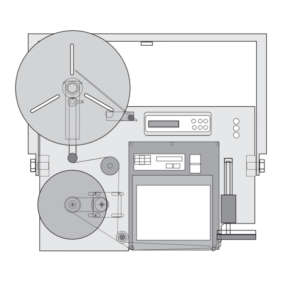
- Page 21 Model 250 Printer Applicator Operators/Technical Manual Section Two 250 Front View Figure 2-1 Front View of the 250 Label Applicator Section 2 Page 2 of 14...
- Page 22 Model 250 Printer Applicator Operators/Technical Manual Section Two 250 Back View Figure 2-2 Back View of the 250 Label Applicator Section 2 Page 3 of 14...
-
Page 23: Tamp Module
Model 250 Printer Applicator Operators/Technical Manual Section Two Tamp Module Figure 2-3 Tamp Assembly Table 2-2 Tamp Module Parts Identification Reference Number Part Name / Identification Function Flow Adjustment / Air Hose Connection, Cylinder Extend Air Cylinder Cylinder Guide Rods... -
Page 24: Pneumatics
Model 250 Printer Applicator Operators/Technical Manual Section Two Table 2-3 Pneumatics Module Reference Part Name or Number Function Pressure Gauges Display 3 station Manifold Solenoid, 4 way valve Regulator w/gauge Vacuum Transducer for Venturi Connection For Muffler Connection to Tamp... -
Page 25: Unwind Assembly
Model 250 Printer Applicator Operators/Technical Manual Section Two Unwind Assembly Figure 2-5 Unwind Block Assembly Table 2-4 Unwind Assembly Reference Reference Number Part Name / Function Number Part Name / Function Unwind Shaft Unwind Shaft End View Unwind Shaft Mounting Block... -
Page 26: Rewind Module
Model 250 Printer Applicator Operators/Technical Manual Section Two Rewind Module Figure 2-6 Rewind Module Table 2-5 Rewind Module Parts Identification Reference Reference Number Part Name / Function Number Part Name / Function Rewind Motor Rewind Motor Pulley Shaft Rewind Shaft Mounting Block... - Page 27 Model 250 Printer Applicator Operators/Technical Manual Section Two Electronics Module Located on the back panel and held on by four bolts. The power supply is located underneath the module and attached with standoffs. Figure 2-7 Electronics Module Table 2-6 Electronics Module Parts Identification...
-
Page 28: Air-Assist Tube Module
Model 250 Printer Applicator Operators/Technical Manual Section Two Air Assist Tube Module attaches to the faceplate and can be adjusted to each label size and material. Air Assist Bracket Bolt Air Assist Bracket Metal Fluted Tube ¼ urethane tubing Figure 2-8 Assist Module with Air Assist Tube Low Label Sensor used for operator notification of low material condition. - Page 29 Model 250 Printer Applicator Operators/Technical Manual Section Two Tamp-Jet Module is used to adapt the tamp application mode to a non-contact method of application. In this mode the cylinder is extended and a blast of air through the tamp pad propels the label to the surface of the product.
- Page 30 Model 250 Printer Applicator Operators/Technical Manual Section Two Figure 2-11 Optional T-Base Stand Module Breakdown Section 2 Page 11 of 14...
- Page 31 Model 250 Printer Applicator Operators/Technical Manual Section Two Figure 2-12 T-Base Stand Parts Identification Table 2-7 T-Base Parts Identification Reference Reference Number Part Name / Function Number Part Name / Function Raising Crank Handle Vertical Post Applicator Mounting Block Mounting Block Lock Handle...
- Page 32 Model 250 Printer Applicator Operators/Technical Manual Section Two T-Base Accessories Identification of parts Table 2-8 T Base Accessory Parts Identification Reference Part Name or Function Number Mounts to Vertical Post, Yard Arm Mounting Plate Mounting Bolt Holes Yard Arm Weldment...
- Page 33 Model 250 Printer Applicator Operators/Technical Manual Section Two Operator Notes Section 2 Page 14 of 14...
- Page 34 Model 250 Printer Applicator Operators/Technical Manual Section Three Section Three Installation 3.1 Unpacking and Setting up the machine If you purchased a T-base stand and received the stand unassembled- locate the cartons that contain the applicator stand. Refer to the section on component location and parts identification pages 11, 12, &13 of 14.
- Page 35 Model 250 Printer Applicator Operators/Technical Manual Section Three If your OEM print engine came in a separate carton from the applicator: Locate the print engine, remove the packing and carefully take engine out of carton. Locate the five bolts that mount the engine to the faceplate. If they are in the faceplate remove them and set aside.
- Page 36 Model 250 Printer Applicator Operators/Technical Manual Section Three Once the printer is mounted onto the faceplate make the following connections to the back of the applicators electrical panel. (ref # 4, figure 3 -6); Figure 3-6 Back Panel of the Electrical Module...
- Page 37 Model 250 Printer Applicator Operators/Technical Manual Section Three The Low Label Sensor, if purchased initially, will be factory installed on the applicator prior to shipping. If the sensor is purchased as an after-market item, follow the table and figure below to install the sensor. (also refer to Parts Identification section for placemen and location of low label sensor on applicators face plate.)
- Page 38 Operators/Technical Manual Section Three The optional 250 Beacon can be used to view and/or notify operators of the conditions and or status of the 250 applicator. The beacon plugs into the back of the electronics module. (see figure 3-6, reference item # 6.
-
Page 39: Label Threading (Sato)
Model 250 Printer Applicator Operators/Technical Manual Section Three Label Threading (SATO) Threading Labels through the applicator can be accomplished in under 30 seconds once you have loaded labels a few times and got the hang of it. The roll of labels you use should be stored in a cool dry climate. - Page 40 Model 250 Printer Applicator Operators/Technical Manual Section Three widths of media that can be used. (Please refer to the print engine manual for an explanation on adjusting these guides.) In figure 3-12 the item marked as #1 is a spring loaded bar that holds the web flat.
-
Page 41: Label Threading (Zebra)
Model 250 Printer Applicator Operators/Technical Manual Section Three Label Threading (ZEBRA) Threading Labels through the applicator can be accomplished in under 30 seconds once you have loaded labels a few times and got the hang of it. The roll of labels you use should be stored in a cool dry climate. - Page 42 Model 250 Printer Applicator Operators/Technical Manual Section Three Media Threading through the Print Engine After accomplishing the loading of labels on the applicator you can now thread the labels on the web through the print engine. This is an abbreviated explanation, for a more in depth procedural description please refer to the print engine manual.
- Page 43 Model 250 Printer Applicator Operators/Technical Manual Section Three Figure 3-17 Annotated parts of the Zebra Print Engine. Front view Section 3 Page 10 of 19...
- Page 44 Model 250 Printer Applicator Operators/Technical Manual Section Three To Load Labels through the Zebra Printer Engine (refer to Figures 3-16 and 3-17 with the following procedure) Grasp the thumbnut (A) and slide the outer media edge guide (B) as far out from the printer frame as possible.
- Page 45 Model 250 Printer Applicator Operators/Technical Manual Section Three Ribbon Loading (ZEBRA) This is an abbreviated procedure for loading ribbon onto the print engine and should only be used as a reference for the re-supply of media after first initially reading the operator manual provided by the manufacturer of the print engine.
- Page 46 Model 250 Printer Applicator Operators/Technical Manual Section Three Figure 3-20 Front view of ribbon threaded through Zebra engine Section 3 Page 13 of 19...
- Page 47 Model 250 Printer Applicator Operators/Technical Manual Section Three ID Technology 250 Label Printer/Applicator with ______________ Series Print Engine INSTALLATION CHECK LIST Customer: Site: Address: Address: City: State Location of equipment: Line speed: Product height: Product handling ok: Spare parts: ON ORDER...
- Page 48 Model 250 Printer Applicator Operators/Technical Manual Section Three PRINT ENGINE SETUP Print Darkness Print Speed Pitch Direction Pitch Offset Zero Slash Auto Online Vert. Offset Hor. Direction Hor. Offset Gap (label) Gap (liner) Input DSW1 LAY OUT DSW2 LAY OUT...
- Page 49 Model 250 Printer Applicator Operators/Technical Manual Section Three APPLICATOR SETUP Has label/web path been adjusted? YES NO Has vacuum system been adjusted? YES NO Has tamp pad height been adjusted for proper label YES NO feed? Check to make sure that the tamp assemblies are not...
-
Page 50: Final System Check
Model 250 Printer Applicator Operators/Technical Manual Section Three FINAL SYSTEM CHECK • Check all bolts for tightness on the mounting stand • Column should be secured in the column mount and not able to rotate. • Raising mechanism needs to be secured in place after desired height of Applicator has been acquired. -
Page 51: Tools Required
Model 250 Printer Applicator Operators/Technical Manual Section Three TOOLS REQUIRED 1 : SET OF METRIC LOOSE BALL END HEX KEYS (1.5 - 10MM) 2 : SET OF STANDARD LOOSE BALL END HEX KEYS 3 : LONG 9/64“ ‘T’ ALLEN 4 : # 1 PHILLIPS SCREWDRIVER... - Page 52 Model 250 Printer Applicator Operators/Technical Manual Section Three Operator Notes Section 3 Page 19 of 19...
- Page 53 Model 250 Printer Applicator Operators/Technical Manual Section 3A The 250 Label Applicator Installation of the Tamp-Jet Module The tamp-jet module is used to create a non-contact method of label application. Once installed the application should follow the following sequence: Printed label is dispensed onto tamp pad, tamp pad is extended to the full reach of the...
- Page 54 Model 250 Printer Applicator Operators/Technical Manual Section 3A Table 3A-2 Tamp-Jet Module Parts Identification Nomenclature Male Run Tee – unifit Nipple Reducer, One – Touch 2-Way D.O. Valve Reducer – One Touch Reducer Nipple 5/16” – ¼” Union Tee Figure 3A-2 Tamp-Jet Module...
- Page 55 Printer Applicator Operators/Technical Manual Section 3A Remove all connectors from the Electronics Module of the 250. That would include the product detector, Flashing Beacon, Printer Connector and Status Output amphenol. Ensure power is off and remove cable. Ensure power plug is removed from the electronics module.
- Page 56 Model 250 Printer Applicator Operators/Technical Manual Section 3A Locate the pneumatics module. After removal of the back cover the module is located to the left side as you are facing the back. Fig. 3A-6 shows the location of the pneumatics module with the arrow.
- Page 57 Model 250 Printer Applicator Operators/Technical Manual Section 3A Install the Tampjet module in port “P” of the pneumatics block. Use your fingers to start the threading of the brass fitting into the port to ensure the threads do not get cross threaded. (The brass fitting spins freely in the Male Run Tee) Using an adjustable wrench, tighten the fitting into port “P”.
- Page 58 Model 250 Printer Applicator Operators/Technical Manual Section 3A Connect the air tubing from the out feed side of the air filter to the Male run Tee fitting on the tamp-jet module. As shown in Figure 3A-10. These are one touch air fittings, therefore all you have to do is insert the tube into the fitting until you feel it stop.
- Page 59 Model 250 Printer Applicator Operators/Technical Manual Section 3A Connect the air tubing from the tampjet module Union Tee (#3) to the Venturi transducer Tee fitting coming out of the pneumatic manifold block Illustrated in Figure 3A-11 below. Connect the air tubing from the union Tee fitting of the tamp-jet module (#4) to the top of the tamp pad.
- Page 60 Model 250 Printer Applicator Operators/Technical Manual Section 3A Connect the electrical plug from the tamp module to the electronic module of the applicator. Run the wire up through the bottom of the electronics module as shown in the figure below. (Arrow shows the knock out on the elctronics module that can be used to thread the wire through.) The connector goes on pin J10.
- Page 61 Model 250 Printer Applicator Operators/Technical Manual Section 3A Return the unit to service by re-installing the back cover. Re-connect all the pheriphals onto the back panel of the electronics module. Re-connect the plant air to the air filter mounted on the applicators u-arm.
- Page 62 250 printer applicator. These signals can be provided to upstream or downstream equipment for monitoring and control. (For example; an upstream case sealer can be temporarily paused while the 250 is offline for label change over.) The system status module can supply the end user with four (4) useable outputs. The...
- Page 63 Model 250 Printer Applicator Operators/Technical Manual Section 3B Your Kit should contain the following components: ITEM DESCRIPTION Mechanical relays, NaiS DS 1 form C Solid state relay, Crydom Series DO 16-pin female receptacle receptacle/wire housing female pins 3/8” Philips head screws...
- Page 64 Model 250 Printer Applicator Operators/Technical Manual Section 3B Installation of the System Status module should take about fifteen minutes. Ensure power is disconnected from the unit. Ensure plant air is disconnected from the unit. Ensure you have received all the necessary components.
- Page 65 Contact Material – Gold-clad silver Rating (restive) – Max. switching power – 60 W, 125 VA Max. switching voltage – 220 V DC, 250 V AC Max. switching current – 2 A DC, AC Max. carrying current – 3 A DC, AC Expected Life (min.
- Page 66 Model 250 Printer Applicator Operators/Technical Manual Section 3B Coil Data (at 20 C 68 Mechanical Relays cont… Nominal Pick up Drop-out Max. allowable V Coil resistance, Voltage V Voltage, V DC voltage, V DC Ω (+ 10%) (max.) (min.) (at 50 C 122 0.15...
- Page 67 Ensure power is off and remove cable. Ensure power plug is removed from the electronics module Remove all connectors from the Electronics Module of the 250. That would include the product detector, Flashing Beacon, and Printer Connector. Section 3B Page 7 of 9...
- Page 68 Model 250 Printer Applicator Operators/Technical Manual Section 3B Disconnect Plant Air from the unit’s air filter connection. Figure 3B-X Location of plant air in on applicators u-arm. Allen wrench (3mm) is needed to remove the back cover. (M4 Cap head bolt) Remove the back cover of the applicator.
- Page 69 Model 250 Printer Applicator Operators/Technical Manual Section 3B Section 3B Page 9 of 9...
-
Page 70: Operational Components Tamp Application
Model 250 Printer Applicator Operators/Technical Manual Section Four Section Four Operational Components Tamp Application: The label is dispensed off of the liner onto a tamp pad and held in place with a Venturi vacuum. When the product is detected, the tamp cylinder... -
Page 71: Rear View
Model 250 Printer Applicator Operators/Technical Manual Section Four The vacuum is created by the flow of air through the holes in the face of the tamp pad (ref # 4, fig 4-5 and fig 4-6), into the vacuum chamber (ref # 10, figure 4-5), through the hose outlet (ref # 5a, figure 4-5) and out the muffler located in the back of the applicator. - Page 72 Model 250 Printer Applicator Operators/Technical Manual Section Four Figure 4-4 Flow Control Valve located on top and on front of air cylinder Figure 4-5 Tamp Pad Assembly (top view on top, front view under that, then tamp pad- bottom view, and last, tamp pad mounting block /...
- Page 73 Model 250 Printer Applicator Operators/Technical Manual Section Four Figure 4-6 Flow of air through tamp pad creating a vacuum. This results from the Venturi effect. Figure 4-7 Air Assist tube Figure 4-8 Peel Tip feeding a label The Label is fed toward the tamp pad as it exits the print engine. The liner is driven around the peel tip of the printer.
-
Page 74: Pneumatics Gauges
Model 250 Printer Applicator Operators/Technical Manual Section Four Pneumatic Gauges: The pressures of the applicator and its modules can be viewed with the three pressure gauges located on the front (top right side) of the faceplate (see figure 4-9). Notice that the gauges can be read from the front or the side. - Page 75 Model 250 Printer Applicator Operators/Technical Manual Section Four STAY CLEAR OF MOVING PARTS, INJURY CAN RESULT FROM MOVEMENT OF TAMP CYLINDER To Change Tamp Pads: 1. Turn OFF the applicator. 2. Remove the plant air hose from the applicators air connection (filter unit).
- Page 76 Model 250 applicator. Upon energizing the 250 Printer Applicator the LCD (Display) will slowly illuminate. The first window that will show up will be the notice that the power is on. On the same window, the next line down will be the notice of the installed version in the firmware.
-
Page 77: Using The Menus
Operators/Technical Manual Section Five Using the menus The menus on the 250 are really quite easy to use. The six buttons on the control panel are used to navigate through the menu structure and make selections. The Up and Down... -
Page 78: Menu Tree
Model 250 Printer Applicator Operators/Technical Manual Section Five Menu Tree • Status Menu (5-16) o Displays all set parameters • Recall Setup (5-14) o Factory • Dwells/Delays (only displayed if “Delay Access” is set to “Yes” in Security) (5-14) o Delay Apply Time Value in mS •... - Page 79 Model 250 Printer Applicator Operators/Technical Manual Section Five • Label Out • Ribbon Out • Supply Low • Supply Out • Online • Tamp Home • Apply Ready • No Select o Status Menu (5-16) o Save Setup (5-14) 1, 2, 3, Factory •...
- Page 80 Model 250 Printer Applicator Operators/Technical Manual Section Five • Time Value in mS Delay Assist • Time Value in mS Dwell Tamp • Time Value in mS Delay Label Feed • Time Value in mS Section 5 Page 5 of 18...
-
Page 81: Print Sequence
Model 250 Printer Applicator Operators/Technical Manual Section Five Print Sequence 1. Normal – If you select the Normal mode in the Print Sequence, Data is downloaded to print engine buffer from a computer, or other label generating device, and a label is printed. When the product detect photo-eye senses the product, it triggers the applicator and the application is accomplished.(tamp,... - Page 82 Model 250 Printer Applicator Operators/Technical Manual Section Five 2. Reverse - If you select the Reverse mode under the Print Sequence menu: Data is downloaded to print engine buffer and resides there until required. When the product detect photo-eye senses the product, the print engine is triggered and a label is then printed and dispensed.
- Page 83 Model 250 Printer Applicator Operators/Technical Manual Section Five Figure 5-3 Data Driven Print Sequence. 3. Data Driven - If you select the Data Driven mode under the Print Sequence menu, the system will be controlled by another system and typically used with a PLC.
- Page 84 Model 250 Printer Applicator Operators/Technical Manual Section Five Figure 5-4 Print Cycle Signal Sequence Section 5 Page 9 of 18...
-
Page 85: Apply Mode
Model 250 Printer Applicator Operators/Technical Manual Section Five Apply Mode 1. Tamp – This selection enables the configuration of the applicator to apply a label using a vacuum tamp pad mounted on an Air Cylinder. Enables the pneumatics used in tamp mode and disables all other configurations. - Page 86 Model 250 Printer Applicator Operators/Technical Manual Section Five 3. Reverse Tamp-Jet - This selection enables the configuration of the applicator to apply a label using a vacuum tamp pad mounted on an Air Cylinder. Enables the pneumatics used in reverse tamp-jet mode and disables all other configurations.
-
Page 87: Outputs
Model 250 Printer Applicator Operators/Technical Manual Section Five Outputs The Outputs menu is used in conjunction with the optional System Status Output Kit. This kit allows the operator and/or systems control personnel to monitor the conditions of the applicator and it’s functions and statuses. For each of the Four (4) menus listed there are ten selections to choose from on what to monitor. - Page 88 Model 250 Printer Applicator Operators/Technical Manual Section Five No Selection – This option disables the output when it is not being used. 1 – Label Low, Ribbon Low, Label Out, Ribbon Out, Toggle through the list Supply Low, Supply Out, On Line, Tamp Home,...
-
Page 89: Recall Set Up
Model 250 Printer Applicator Operators/Technical Manual Section Five Save Set-up 1. 1– Saves the set-up you selected in this session 2. 2 – to one of the three buffers listed. Annotate the saved set-up in the front of your manual on the 3. -
Page 90: Dwells And Delays
Model 250 Printer Applicator Operators/Technical Manual Section Five Dwell Tamp – Increasing the value of this setting/toggle will cause the tamp to remain in the extended position longer. Decreasing the value will shorten the time the cylinder stays extended. This adjustment does NOT affect the speed or power of the cylinder extending or retracting. -
Page 91: Status Menu
Model 250 Printer Applicator Operators/Technical Manual Section Five Status Menu The Status menu is used to review each parameter and it’s current setting. By using the up and down arrows, each item and the current value will be displayed. This is helpful when setting another controller or recording settings in your manual. -
Page 92: Password Entry / Security
The security menu gives users the ability to limit access to the parameters of the Model 250. At the most limited setting, the operator only has the ability to view the status menu and recall any of the four saved setups. If it is enabled, the operator may also have the ability to change the Delay Apply value in order to alter the label position on the product. - Page 93 Model 250 Printer Applicator Operators/Technical Manual Section Five Operator Notes Section 5 Page 18 of 18...
-
Page 94: Maintenance And Troubleshooting
Model 250 Printer Applicator Operators/Technical Manual Section Six Section Six Maintenance and Troubleshooting Front View Face Plate with Back Cover Shown Section 6 Page 1 of 20... - Page 95 Model 250 Printer Applicator Operators/Technical Manual Section Six Side View with SATO 8485SE installed Side View of Print Engine Area with Zebra Pax Engine Installed Section 6 Page 2 of 20...
- Page 96 Model 250 Printer Applicator Operators/Technical Manual Section Six Bottom View with SATO 8485SE Installed 250 Pin out for the 16-Pin Status Output connector Nomenclature Normal Status Output 2 Open Output 2 Closed Output 2 Common Output 3 Open Output 3...
- Page 97 Model 250 Printer Applicator Operators/Technical Manual Section Six Electronic Module Ref# Part Name / Function Power Input Module Power In Cable 16-pin Status Output Electronic Module housing Air (blow on) Tamp (tamp on) Tamp-Jet Vacuum LCD Window Operator Input Function...
- Page 98 Model 250 Printer Applicator Operators/Technical Manual Section Six Pins Outs of the 250 Applicator Beacon 9 pin Female D Connector PIN FUNCTION Red Beacon +24 VDC Amber Beacon Green Beacon Signal Duplication of Product Detect Pin Duplication of Product Detect Pin...
- Page 99 Model 250 Printer Applicator Operators/Technical Manual Section Six Tamp Home PIN FUNCTION +24 VDC Signal (sink) Signal (sink) Auxiliary Input PIN FUNCTION +24 V Signal (sink) Signal (sink) Printer Interface 15 pin Female D Connector PIN FUNCTION From printer 5 VDC...
- Page 100 Model 250 Printer Applicator Operators/Technical Manual Section Six Valves PIN FUNCTION 1 Air Assist Valve Control 1 Tamp Valve Control 1 Jet Valve Control 1 Vacuum Valve Control Fan, blow-off module PIN FUNCTION 1 +24 VDC Rewind Motor “RR” PIN FUNCTION...
- Page 101 Model 250 Printer Applicator Operators/Technical Manual Section Six Printer / Applicator Interface Cable Pin Mapping FUNCTION 5 VDC Print enable Feed Pause Reprint Low ribbon Service 10,14 Required Print end Label out Ribbon out Online Sato “Se” series printers require “Ext Pin 9” configured to Mode 2. Consult printer manual “Service Mode Configuration”...
-
Page 102: Troubleshooting Guide
Model 250 Printer Applicator Operators/Technical Manual Section Six ID TECHNOLOGY 250 TROUBLESHOOTING GUIDE SYMPTOM DIAGNOSIS SOLUTION Nothing works, 1. Power cord for applicator Inspect and correct applicator and loose, defective or not printer does not plugged in. have power 2. Main supply fuse is blown. - Page 103 Model 250 Printer Applicator Operators/Technical Manual Section Six SYMPTOM DIAGNOSIS SOLUTION Label advance 1. Product detector Refer to 250 manual for does not occur incorrectly aligned. set-up instructions. 2. Product detector Correct or replace as disconnected from necessary. machine or cable damaged.
- Page 104 Report to label manufacturer if problem persists. 3. Poor product guidance. Inspect and correct. 4. Product detector not Refer to 250 manual for correctly positioned. set-up instructions. 5. Incorrect product delay. Refer to 250 manual for set-up instructions. 6. Smart tamp sensor out of Inspect and correct.
- Page 105 1. Product detector loose or Inspect and correct. occur at random vibrating. without being initiated. 2. Product detector Refer to 250 manual for alignment too marginal or set-up instructions. set too sensitive. Inspect and request 3. Loose wiring connections. qualified assistance if required.
- Page 106 Model 250 Printer Applicator Operators/Technical Manual Section Six SYMPTOM DIAGNOSIS SOLUTION Waste take up runs Incorrect mode setting in print Correct. continuously. engine. Label liner not Rewind reel slip clutch Request qualified service rewinding correctly. malfunctioning or broken assistance. drive belt.
- Page 107 Model 250 Printer Applicator Operators/Technical Manual Section Six SYMPTOM DIAGNOSIS SOLUTION Misregistration or 1. Label Sensor is not Adjust Label Sensor. skips labels. positioned correctly. 2. Label Sensor not Check sensor threshold. calibrated. 3. Media does not meet Use media that meets specifications.
- Page 108 This is only a guide and is not intended for use as a complete source. Please refer to your operator/maintenance manual for complete information on the printer you are using. For parts and service, please call: ID Technology Corporate Office at (888) 438-3242 ID Technology Technical Support Section 6 Page 15 of 20...
-
Page 109: Timing Cycles
Model 250 Printer Applicator Operators/Technical Manual Section Six Timing Cycles Section 6 Page 16 of 20... - Page 110 Model 250 Printer Applicator Operators/Technical Manual Section Six Section 6 Page 17 of 20...
- Page 111 Model 250 Printer Applicator Operators/Technical Manual Section Six Section 6 Page 18 of 20...
- Page 112 Model 250 Printer Applicator Operators/Technical Manual Section Six Section 6 Page 19 of 20...
- Page 113 Model 250 Printer Applicator Operators/Technical Manual Section Six Operator Notes Section 6 Page 20 of 20...
- Page 114 MODEL 250 IDT BOM (STD MACHINE) MANUAL VERSION Model 250 Standard Machine LEVEL 1 LEVEL 2 LEVEL 3 LEVEL 4 ITEM QTY ITEM QTY ITEM QTY ITEM QTY PART NO DESCRIPTION BASE MODULE 62000 ASSY BASE MODULE U-ARM ASSEMBLY 62001...
- Page 115 MODEL 250 IDT BOM (STD MACHINE) MANUAL VERSION Model 250 Standard Machine LEVEL 1 LEVEL 2 LEVEL 3 LEVEL 4 ITEM QTY ITEM QTY ITEM QTY ITEM QTY PART NO DESCRIPTION BASE MODULE SHCS M4 X 30 S/S PLAIN WASHER #8 S/S...
- Page 116 MODEL 250 IDT BOM (4 in. STROKE TAMP) (OPT) LEVEL 1 LEVEL 2 LEVEL 3 LEVEL 4 ITEM QTY ITEM QTY ITEM QTY ITEM QTY PART NO DESCRIPTION VENDOR VENDOR P/N Accessories 62200-04 4 INCH TAMP ASSEMBLY 62251 TAMP BLOCK...
- Page 117 ITEM QTY ITEM QTY ITEM QTY ITEM QTY PART NO DESCRIPTION BASE MODULE .00 ± .02 62000 ASSY BASE MODULE (RH) Model 250 .000 ± .005 U-ARM ASSEMBLY ANGLES ± 2° 62001 UNIVERSAL BRACKET BASE PLATE ASSEMBLY DESCRIPTION 62009 ASSY. BASE PLATE...
- Page 118 ITEM QTY ITEM QTY ITEM QTY ITEM QTY PART NO DESCRIPTION BASE MODULE 62000 ASSY BASE MODULE (RH) .00 ± .02 U-ARM ASSEMBLY Model 250 .000 ± .005 62001 UNIVERSAL BRACKET ANGLES ± 2° BASE PLATE ASSEMBLY DESCRIPTION 62009 ASSY. BASE PLATE...
- Page 119 QTY ITEM QTY ITEM QTY PART NO DESCRIPTION BASE PLATE ASSEMBLY 62009 ASSY. BASE PLATE 62010 PLATE,BASE 62011 BRACKET,BASE PLATE 62030-08 ROLL,IDLER 62031 SHAFT,IDLER 62034 SPACER,ROLL 62015-08 COLLAR,SPRING - 1" 62030-16 ROLL,IDLER 62031 SHAFT,IDLER 62034 SPACER,ROLL 62017 STANDOFF,COVER 62016 COVER 62012 LABEL,NAMEPLATE 62120...
- Page 120 11/24/2003 MODEL 250 UNWIND ASSEMBLY THE INFORMATION CONTAINED IN THIS DRAWING IS THE SOLE PROPERTY OF ID TECHNOLOGY,CORP. ANY REPRODUCTION IN 62020 PART OR WHOLE WITHOUT THE WRITTEN PERMISSION OF ID TECHNOLOGY IS PROHIBITED.
-
Page 121: Rewind Assembly
MODEL 250 menmi 11/24/2003 REWIND ASSEMBLY THE INFORMATION CONTAINED IN THIS DRAWING IS THE SOLE PROPERTY OF ID TECHNOLOGY,CORP. ANY REPRODUCTION IN 62050 PART OR WHOLE WITHOUT THE WRITTEN PERMISSION OF ID TECHNOLOGY IS PROHIBITED. - Page 122 MODEL 250 CHECKED TITLE PNEUMATIC ASSEMBLY APPROVED THE INFORMATION CONTAINED IN THIS DRAWING IS THE SOLE SIZE DWG NO PROPERTY OF ID TECHNOLOGY,CORP. ANY REPRODUCTION IN 62100 PART OR WHOLE WITHOUT THE WRITTEN PERMISSION OF ID TECHNOLOGY SCALE IS PROHIBITED. SHEET...
- Page 123 12/09/2003 MO DEL 250 4" TAMP ASSEMBLY TH E INFORMA TION CONT AINED IN THIS DRAWING IS THE SOLE PROPERTY O F ID TECHNOLO GY,CORP. ANY REPRODUCTION IN PART O R WHOL E WITHOUT THE WR ITTEN PERMISSION OF ID TECHNO LOGY 62200-04 IS PROHIBITED.
- Page 124 01/08/2004 MODEL 250 8" SWING TAMP ASSEMBLY THE INFORMATION CONTAINED IN THIS DRAWING IS THE SOLE PROPERTY OF ID TECHNOLOGY,CORP. ANY REPRODUCTION IN 62201-08 PART OR WHOLE WITHOUT THE WRITTEN PERMISSION OF ID TECHNOLOGY IS PROHIBITED.
- Page 125 01/15/2004 MODEL 250 TAMP BRACKET HEAVY DUTY THE INFORMATION CONTAINED IN THIS DRAWING IS THE SOLE PROPERTY OF ID TECHNOLOGY,CORP. ANY REPRODUCTION IN 62260-12 PART OR WHOLE WITHOUT THE WRITTEN PERMISSION OF ID TECHNOLOGY IS PROHIBITED.
- Page 126 ITEM QTY ITEM QTY ITEM QTY ITEM QTY PART NO DESCRIPTION Accessories 62280 TAMP JET KIT ASSEMBLY 62281 2-WAY D.O. VALVE...
- Page 127 250 PRECISION TILT 2051 FRANKLIN DR. FORT WORTH, TX 76106...
- Page 128 3. PLACE THE TS9100 IN POSITION USING THE M20 HEX HEAD BOLT AND THE TWO M6 SOCKET HEAD CAP SCREWS. 4. FASTEN THE LEVELING BRACKET TO THE U-ARM WITH M8 SOCKET HEAD CAP SCREW. menmi 8/8/2005 ID TECHNOLOGY DETAIL A PRECISION LEVELING ASSEMBLY TS9100 Installation...
- Page 129 Model 250 Printer Applicator Operators/Technical Manual Appendix 2 CORRECTLY SETTING UP A TAMP PAD TO A PEEL EDGE In Figure 1 the peel edge of a printer or peel plate, the tamp pad, and air assist tube are all shown. To correctly set up a tamp pad to a peel edge two things must be kept in mind.
- Page 130 Tamp pad and assist in pushing the label out on the pad. With the proper setup on the printer or applicator the label should feed completely, covering the ID 250 tamp pad Note Figure 2 label...
- Page 131 Model 250 Printer Applicator Operators/Technical Manual Appendix 2 After the label is dispensed out on the Tamp pad verify that the label is sitting below the peel edge. Also check to make sure the label is not going to catch the air assist tube when the machine starts to cycle to place a label on a product.
Need help?
Do you have a question about the 250 and is the answer not in the manual?
Questions and answers