Sign In
Upload
Manuals
Brands
ID Technology Manuals
Label Maker
250
ID Technology 250 Manuals
Manuals and User Guides for ID Technology 250. We have
1
ID Technology 250 manual available for free PDF download: Operator / Technical Manual
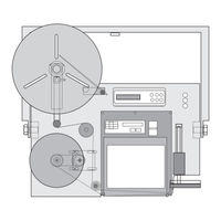
ID Technology 250 Operator / Technical Manual (132 pages)
Print and Apply
Brand:
ID Technology
| Category:
Label Maker
| Size: 6.06 MB
Table of Contents
Table of Contents
2
Electronic Module
9
Serial Numbers
9
Applicator Set up
10
Print Engine Set up
10
Test Print Engine
10
Final System Check
11
Symbols
13
The 250 Label Printer Applicator
14
Section One
15
Standard Features
15
Air Requirements
16
Electrical
16
Product Sensing
16
Weight
16
Available Upgrades
17
Printers
17
The T-Base Support Stand
17
12” Height Adapter
18
Precision Slide Base
18
The Traversing Yard Arm
18
Yard Arm
18
Packaging Your RA
19
General Specifications
15
Dimensions Front View
15
General Specifications
15
Overall Dimensions
15
Section Two
20
250 Front View
21
Front View of the 250 Label Applicator
21
250 Back View
22
Back View of the 250 Label Applicator
22
Tamp Assembly
23
Tamp Module
23
Tamp Module Parts Identification
23
Pneumatics Assembly All Views
24
Pneumatics Module
24
Unwind Assembly
25
Rewind Module
26
Rewind Module Parts Identification
26
Electronics Module
27
Electronics Module Parts Identification
27
Assist Module with Air Assist Tube
28
Low Label Sensor (Front and Top View)
28
Optional Tamp-Jet Module
29
Optional T-Base Stand Module Breakdown
30
T-Base Stand Parts Identification
31
T-Base Accessories Identification of Parts
32
3.1 Unpacking and Setting up the Machine
34
Component Location and Identification
20
Identification of the 250 Components
20
Section Three
34
U-Arm
34
U-Arm Placement on Applicator
34
Back Panel of the Electrical Module
36
Low Label Sensor
37
Label Threading (SATO)
39
Outer Flange with Hub Decal in Center
39
Web Path through the Applicator and Printer
39
Label Threading (ZEBRA)
41
Annotated Parts of the Zebra Print Engine. 3D View
42
Media Threading through the Print Engine
42
Annotated Parts of the Zebra Print Engine. Front View
43
Front View of Label Web Threaded through Zebra Engine
44
To Load Labels through the Zebra Printer Engine
44
Ribbon Loading (ZEBRA)
45
Front View of Ribbon Threaded through Zebra Engine
46
Final System Check
50
Tools Required
51
Installation of the Tamp-Jet Module
53
Tamp-Jet Module Parts Connections
53
Tamp-Jet Module Parts Identification
54
Electronics Module, Back View, Connector Identification
55
Location of Air Filter on U-Arm
55
Location of Back Cover Mounting Bolts
55
Location of One Touch Brass Fitting. Back View
56
Location of One Touch Brass Fitting. Side View
56
Location of Pneumatics Module
56
Plant Air to Air Filter to Tamp-Jet Module Plumbing
58
Plumbing from Tamp Module to Pneumatic Block and Tamp Pad
59
Description and Installation of the System Status Module
62
System Status Module Parts
64
System Status Parts and Location
64
Disconnect Plant Air from the Unit’s Air Filter Connection
68
Location of Plant Air in on Applicators U-Arm
68
Installation
34
Section 3B Installation of System Status Module
70
Section 3A Installation of Tamp-Jet Module
70
Section Four
70
Tamp Application
70
Tamp on Description
70
Tamp Pad Assembly
72
Air Assist Tube
73
Peel Tip Feeding a Label
73
Air Pressure Adjustment Screws
74
Pneumatic Gauges
74
Pressure Gauges Front and Side View
74
Tamp Pad Mounted to Mounting Bracket
75
To Change Tamp Pads
75
Operational Components
70
Section Five
76
The Printer
76
Using the Menus
77
Menu Tree
78
Normal Print Sequence
81
Print Sequence
81
Reverse Print Sequence
82
Data Driven Print Sequence
83
Print Cycle Signal Sequence
84
Apply Mode
85
Tamp
85
Tamp-Jet
85
Air-Jet
86
Reverse Tamp-Jet
86
Label Low
87
Outputs
87
Ribbon Low
87
Tamp Home
87
No Selection
88
Delay Apply
89
Dwells / Delays
89
Recall Set up
89
Save Set up
89
Delay Label Feed
90
Dwell Tamp
90
Status Menu
91
Vacuum Mode
91
Delay Access
92
Enable Security
92
Password Entry / Security
92
Face Plate with Back Cover Shown
94
Front View
94
Operating Procedures
76
Section Six
94
Side View of Print Engine Area with Zebra Pax Engine Installed
95
Side View with SATO 8485SE Installed
95
250 Pin out for the 16-Pin Status Output Connector
96
Bottom View with SATO 8485SE Installed
96
16-Pin Connector on Electronics Module
97
Pins Outs of the 250 Applicator
98
15 Pin Female D Connector
99
Printer / Applicator Interface Cable Pin Mapping
101
ID Technology 250 Troubleshooting Guide
102
Timing Cycles
109
Model 250 Standard Machine
114
Base Module Assembly
117
Correctly Setting up a Tamp Pad to a Peel Edge
129
Maintenance and Troubleshooting
94
Advertisement
Advertisement
Related Products
ID Technology 252
ID Technology Categories
Label Maker
Industrial Equipment
More ID Technology Manuals
Login
Sign In
OR
Sign in with Facebook
Sign in with Google
Upload manual
Upload from disk
Upload from URL