Table of Contents
Advertisement
Quick Links
Code : SEA 303
ASSEMBLY MANUAL
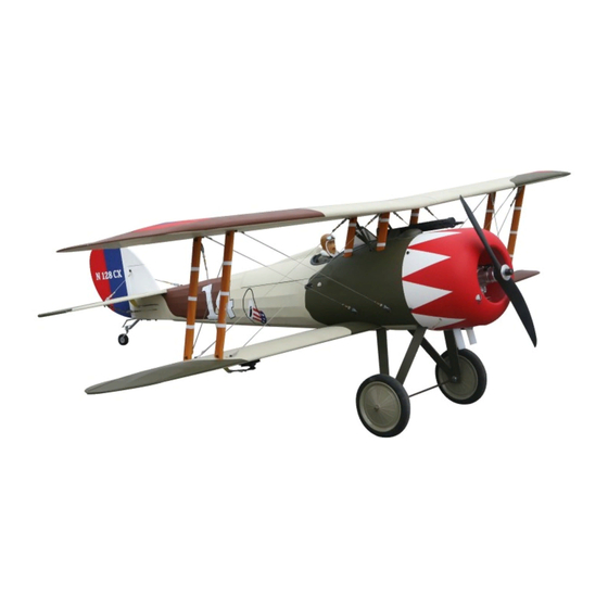
Specifications:
Wingspan--------------- 68.0 in (172.7 cm).
Wing area--------------- 1155.7 sq.ins (74.6 sq.dm).
Weight------------------- 12.8-13.2 lbs (5.8-6.0 kg).
Length------------------- 55.0 in (139.8 cm).
Engine/Motor size----- 20-26cc gasoline.
Radio--------------------- 5 channels with 6 servos.
1
Advertisement
Table of Contents

Related Manuals for Seagull Models NIEUPORT 28 REPLICA


Summary of Contents for Seagull Models NIEUPORT 28 REPLICA
-
Page 1: Specifications
Code : SEA 303 ASSEMBLY MANUAL Specifications: Wingspan--------------- 68.0 in (172.7 cm). Wing area--------------- 1155.7 sq.ins (74.6 sq.dm). Weight------------------- 12.8-13.2 lbs (5.8-6.0 kg). Length------------------- 55.0 in (139.8 cm). Engine/Motor size----- 20-26cc gasoline. Radio--------------------- 5 channels with 6 servos. - Page 2 Instruction Manual. NIEUPORT 28 REPLICA INTRODUCTION. NIEUPORT 28 REPLICA Thank you for choosing the ARTF by SG MODELS . The NIEUPORT 28 REPLICA was designed with the intermediate/advanced sport flyer in mind. It is a semi scale airplane which is easy to fly and quick to assemble. The air- frame is conventionally built using balsa, plywood to make it stronger than the av- erage ARTF, yet the design allows the aeroplane to be kept light.
-
Page 3: Kit Contents
KIT CONTENTS. HINGING THE AILERON. NIEUPORT 28 REPLICA SEA303 Note : The control surfaces, including the ailer- 1. Fuselage ons, elevators, and rudder, are prehinged with 2. Upper wing set hinges installed, but the hinges are not glued in 3. Lower wing set place. - Page 4 Instruction Manual. NIEUPORT 28 REPLICA 4) Deflect the aileron and completely sat- 7) Repeat this process with the other urate each hinge with thin C/A glue. The wing panel, securely hinging the aileron ailerons front surface should lightly con- in place tact the wing during this procedure.
- Page 5 2) Use dental floss to secure the connec- tion so they cannot become unplugged. Epoxy. Ailerons control horn INSTALLING THE ALLERON SERVOS. 3) A string has been provided in the wing to pull the aileron lead through to the wing root. Remove the string from the wing at the servo location and use the tape to attach it to the servo extension lead.
-
Page 6: Aileron Pushrod Installation
Instruction Manual. NIEUPORT 28 REPLICA AILERON PUSHROD INSTALLATION. Please see below pictures. 30mm... - Page 7 INSTALLING THE FUSELAGE SERVOS. INSTALLING THE RECEIVER SWITCH. Because the size of servos differ, you Install the switch into the precut hole in may need to adjust the size of the precut the side, in the fuselage. opening in the mount. The notch in the sides of the mount allow the servo lead to pass through.
- Page 8 Instruction Manual. NIEUPORT 28 REPLICA Switch. INSTALLING THE MAIN LANDING GEAR TO FUSELAGE. Please see these below pictures.
-
Page 9: Installing The Stopper Assembly
M3x4 INSTALLING THE STOPPER ASSEMBLY. 1) Using a modeling knife, carefully cut off the rear portion of one of the 3 nylon tubes leaving 1/2” protruding from the rear of the stopper. This will be the fuel pick up tube. 2) Using a modeling knife, cut one length of silicon fuel line. -
Page 10: Fuel Tank Installation
Instruction Manual. NIEUPORT 28 REPLICA Vent tube. Fuel pick up tube. Fuel fill tube. 3) Carefully bend the second nylon tube up at a 45º angle. This tube is the vent tube. 4) Test fit the stopper assembly into the tank. -
Page 11: Engine Mount Installation
Blow through one of the lines to ensure the fuel lines have not become kinked inside the fuel tank compartment. Air should flw Balsa wood. through easily. ENGINE MOUNT INSTALLATION. 1) Locate the items necessary to install the engine mount included with your model. -
Page 12: Mounting The Engine
Instruction Manual. NIEUPORT 28 REPLICA 4) On the fie wall has the location for the throttle pushrod tube (pre-drill). MOUNTING THE ENGINE. 5) Slide the pushrod tube in the fiewall and guide it through the fuel tank mount. 1) Position the engine with the drive... - Page 13 COWLING. Please see below pictures. 8) Reinstall the servo horn by sliding the connector over the pushrod wire. Cent- er the throttle stick and trim and install the servo horn perpendiular to the servo center line. 9) Move the throttle stick to the closed po- sition and move the carburetor to closed.
- Page 14 Instruction Manual. NIEUPORT 28 REPLICA 1) Tape the cowl to the fuselage using low-tack tape. 4) Install the muffl and muffl extension onto the engine and make the cutout in the cowl for muffl clearance. Connect the fuel and pressure lines to the carburetor, muffl and fuel filer valve.
- Page 15 ELECTRIC POWER CONVERSION. 1) Locate the items neccessary to install the electric power conversion included with your model. M4x25mm and washers. 4) Attach the motor to the front of the electric motor box using four 4mm blind nut, four M4x20mm hex head bolts to se- cure the motor.
- Page 16 Instruction Manual. NIEUPORT 28 REPLICA Then, use 5.5mm drill bit to enlarge the holes on the electric motor box. 145mm 5.5mm Blind nut. Balsa stick. Epoxy. 5) Attach the motor to the front of the electric motor box using four 4mm blind...
-
Page 17: Installing The Spinner
Install the spinner backplate, propeller and spinner cone. Battery. The propeller should not touch any part of the spinner cone. If it does, use a sharp modeling knife and carefully trim away the spinner cone where the propel- ler comes in contact with it. HINGING THE ELEVATOR. -
Page 18: Installing The Horizontal Stabilizer
Instruction Manual. NIEUPORT 28 REPLICA INSTALL ELEVATOR CONTROL HORN. Draw center line. Fiberglass control horn. Using a modeling knife, carefully rmove the covering at mounting slot of horizontal stabilizer (both side of fuse- lage). Epoxy. Cut. ElevatorFiberglass control horn. 3) Slide the stabilizer into place in the precut slot in the rear of the fuselage. - Page 19 7) When you are sure that everything is aligned correctly, mix up a generous amount of 30 Minute Epoxy. Apply a thin layer to the top and bottom of the stabilizer mounting Pen. area and to the stabilizer mounting platform sides in the fuselage.
- Page 20 Instruction Manual. NIEUPORT 28 REPLICA 1) While holding the vertical stabilizer firmly in place, use a pen and draw a line on each side of the vertical stabilizer where it meets the top of the fuselage. Fiberglass control horn. Epoxy.
- Page 21 Epoxy. 3) Slide the vertical stabilizer back in place. Using a triangle, check to ensure 4) When you are sure that everything is that the vertical stabilizer is aligned 90º aligned correctly, mix up a generous amount to the horizontal stabilizer. of Flash 30 Minute Epoxy.
- Page 22 Instruction Manual. NIEUPORT 28 REPLICA Elevator pushrod. M2 clevis. Hex nut. Elevator control horn. Fuel tubing. 3) Thread one clevis and M2 lock nut on to each elevator control rod. Thread the horns on until they are flush with the ends of the control rods.
-
Page 23: Mounting The Tail Wheel
MOUNTING THE TAIL WHEEL. C/A glue. Locate items necessary to install tail wheel. - Page 24 Instruction Manual. NIEUPORT 28 REPLICA M3x15...
-
Page 25: Top View
IINSTALL BRACING WIRE AND METAL BRACKET AT THE TAIL. TOP VIEW M3x15... -
Page 26: Bottom View
Instruction Manual. NIEUPORT 28 REPLICA BOTTOM VIEW M3x15... - Page 27 IINSTALL OF PLASTIC. Please see below pictures.
- Page 28 Instruction Manual. NIEUPORT 28 REPLICA 2x8mm. M3x10...
- Page 29 M3x10 3x25mm.
- Page 30 Instruction Manual. NIEUPORT 28 REPLICA Epoxy. Epoxy.
- Page 31 4) Position the windshield onto the fuse- lage. Trace around the windshield onto the fuselage using a felt-tipped pen. Cut and remove the covering from between the lines drawn, and glue the windshield to the fuselage using epoxy or a special canopy glue.
- Page 32 Instruction Manual. NIEUPORT 28 REPLICA 2x8mm.
-
Page 33: Cabane Strut Installation
CABANE STRUT INSTALLATION. NOTE : Ths is temporary steps for in- stalling screws, so no need to tighten the screws.. Th exact position of the end will be adjusted when the struts are installed.. 1) Loacte the items for this section of the manual. - Page 34 Instruction Manual. NIEUPORT 28 REPLICA 3x12mm.
- Page 35 3) Place the upper center wing rib in po- ATTACHMENT WING- FUSELAGE. sition on the cabane struts. Start the M3 x 12 socket head machine screws and M3 Attach the aluminium tube into fuselage. washers that secure the rib to the cabane struts.
- Page 36 Instruction Manual. NIEUPORT 28 REPLICA Insert two lower wing panels as pictures below.. M4x12...
- Page 37 INSTALLATION WING STRUTS. 1) Loacte the items for this section of the manual 2) Attach the two wing struts to the top of lower wing pant using an M3x12mm nachine screw and M3 washers.
- Page 38 Instruction Manual. NIEUPORT 28 REPLICA...
-
Page 39: Installation Cable
At this time, exact position of the end is set, please Use a 2.5mm hex wrench to slowly tighten the hardware securing the cabane struts in position on the fuselage. Again, make sure to use threadlock on all the fasteners to prevent them from vi- brating loose Repeat steps to prepare the remaining wing panel for installation. -
Page 40: Removing The Wing Panels
Instruction Manual. NIEUPORT 28 REPLICA 2)Attach the clevis to the brass tab next to the rear interplane strut on the upper- lower wing.Slide a copper crimp on the cable. Pass the cable through the brass tab on the upper wing, the back through the REMOVING THE WING PANELS. -
Page 41: Apply The Decals
Using the transport frames allow the re- moval of the wings without the need to remove the aileron linkage and the inter- plane strut between the top and bottom wings. INSTALLING THE BATTERY-RECEVER. 1) Plug the servos leads and the switch lead into the receiver. -
Page 42: Control Throws
Instruction Manual. NIEUPORT 28 REPLICA Lift the model. If the tail drops when BALANCING. you lift, the model is “tail heavy” and you must add weight* to the nose. If the nose 1) It is critical that your airplane be drops, it is “nose heavy”... - Page 43 15-25mm 15-25mm 20-30mm Fuselage 20-30mm 15-25mm Wing 15-25mm...
-
Page 44: Flight Preparation
A) Plug in your radio system per the 2) Check every bolt and every glue manufacturer’s instructions and turn eve- joint in the NIEUPORT 28 REPLICA to rything on. ensure that everything is tight and well bonded. - Page 45 If you have any queries, or are interested in our products, please feel free to contact us Factory : 12/101A - Hamlet 4 - Le Van Khuong Street - Dong Thanh Ward - Hoc Mon District - Ho Chi Minh City - Viet Nam. Office : 62/8 Ngo Tat To Street - Ward 19 - Binh Thanh District - Ho Chi Minh City - Viet Nam Phone : 848 - 86622289 or 848- 36018777...
Need help?
Do you have a question about the NIEUPORT 28 REPLICA and is the answer not in the manual?
Questions and answers