Table of Contents
Advertisement
MS:158
ASSEMBLY MANUAL
"Graphics and specifications may change without notice".
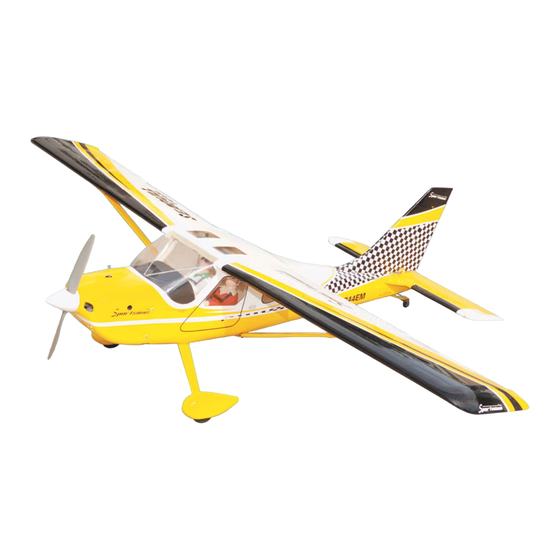
Specifications:
Wing span ------------------------------70.9in (180cm).
Wing area -----------------644.8sq.in (41.6sq dm).
Weight ------------------------9.5-11.5lbs (4.3-5.2kg).
Length ------------------------------49.2n (125.0cm).
Engine ------------------ 0.75-0.91cu.in -----2-stroke.
0.91-1.10cu.in -----4-stroke.
Radio ------------------- 6 channels with 8 servos.
Electric conversion: optional
Advertisement
Table of Contents

Related Manuals for Seagull Models GLASAIR SPORTSMAN 2-2


Summary of Contents for Seagull Models GLASAIR SPORTSMAN 2-2
- Page 1 MS:158 ASSEMBLY MANUAL “Graphics and specifications may change without notice”. Specifications: Wing span ------------------------------70.9in (180cm). Wing area -----------------644.8sq.in (41.6sq dm). Weight ------------------------9.5-11.5lbs (4.3-5.2kg). Length ------------------------------49.2n (125.0cm). Engine ------------------ 0.75-0.91cu.in -----2-stroke. 0.91-1.10cu.in -----4-stroke. Radio ------------------- 6 channels with 8 servos. Electric conversion: optional...
-
Page 2: Kit Contents
SPORTSMAN 2-2 is simply a joy. This instruction manual is designed to help you build a great flying aeroplane. Please read this manual thoroughly before starting assembly of your GLASAIR SPORTSMAN 2-2 . Use the parts listing below to identify all parts. -
Page 3: Additional Items Required
www.seagullmodels.com CONTENTS.TS INSTALL THE AILERONS CONTROL HORN. Fuselage Wing set Tail set Cowling Wing sube Wheel pants(2) Seat(2) Pilots Tail wheel Struts Fiberglass control horn. Landing gear Fuel tank canopy Wheels and spinner Engine mount LED lights Hardware bag included ADDITIONAL ITEMS REQUIRED. - Page 4 Instruction Manual. GLASAIR SPORTSMAN 2-2 Elevatorcontrol horn. Epoxy Epoxy INSTALL RUDDER CONTROL HORN. Flap control horn. Repeat steps to install the rudder control horn as same as steps done for ailerons. Epoxy Fiberglass control horn. INSTALL ELEVATOR CONTROL HORN. Epoxy.
-
Page 5: Engine Mount Installation
www.seagullmodels.com INSTALLING THE STOPPER ASSEMBLY. ENGINE MOUNT INSTALLATION. 1) Using a modeling knife, carefully cut 1) Locate the items necessary to install the off the rear portion of one of the 3 nylon tubes engine mount included with your model. . leaving 1/2”... -
Page 6: Fuel Tank Installation
Instruction Manual. GLASAIR SPORTSMAN 2-2 8) Use plywood template to hold in place 3) Carefully bend the second nylon tube the fuel tank with C/A glue to secure the fuel up at a 45º angle. This tube is the vent tube. -
Page 7: Installing The Fuselage Servos
www.seagullmodels.com Loctite secure. Adjustable Servo connector. Servo arm. 1 PCS. Throttle servo arm. Rudder servo arm. Blow through one of the lines to en- sure the fuel lines have not become kinked inside the fuel tank compartment. Air should flow through easily. INSTALLING THE FUSELAGE SERVOS. - Page 8 Instruction Manual. GLASAIR SPORTSMAN 2-2 4) Slide the collar to the axle and setscrew the collars to secure the collar to the axle and then slider the wheel on the axle with a drop of oil on the axle so the wheel will spin freely when installed.
-
Page 9: Installing The Main Landing Gear
www.seagullmodels.com Repeat steps as above to attach remain- ing wheel pants to the landing gear. Landing Gear. wheel Pant. INSTALLING THE MAIN LANDING GEAR. C/A glue. 1) The blind nuts for securing the landing gear are already mounted inside the fuselage. 2) Using the hardware provided, mount the main landing gear to the fuselage. - Page 10 Instruction Manual. GLASAIR SPORTSMAN 2-2 5) Slide the pushrod tube in the firewall and guide it through the fuel tank mount. Use 4mm. medium C/A to glue the tube to the firewall and the fuel tank mount. 6) Connect the Z-bend in the 450mm throttle pushrod to the outer hole of the carburetor arm.
- Page 11 www.seagullmodels.com 2)Install LED lights at the top Cowling. COWLING. 1)Slide the fiberglass cowl over the engine and line up the back edge of the cowl with the marks you made on the fuselage then trim and cut as shown. Drill a hole 5mm. Trim and cut.
- Page 12 Instruction Manual. GLASAIR SPORTSMAN 2-2 3) Install the muffler and muffler extension onto the engine and make the cutout in the cowl for muffler clearance. Connect the fuel C/A glue. and pressure lines to the carburetor, muffler and fuel filler valve. Secure the cowl to fuse- lage using the M3x10mm screws.
- Page 13 www.seagullmodels.com M4x20mm 4mm. 3) Attach the motor to the front of the electric motor box using four 4mm blind nut, four M3x15mm hex head bolts to secure the motor. Please see picture shown. Blind nut. M3x15mm. 4mm. 145mm.
-
Page 14: Installing The Spinner
Instruction Manual. GLASAIR SPORTSMAN 2-2 Recomend Mounting Speed Control inside Balsa stick. Fuselage If Flying off Water. Electric motor. Speed control. Epoxy. 4) Locate the plywood battery tray to the fuselage. Tighten the screws using machine screws M3x15mm to secure the tray in position. -
Page 15: Installing The Aileron - Flap Servos
www.seagullmodels.com INSTALLING THE AILERON - FLAP SERVOS. 4) Apply 2-3 drops of thin C/A to each of the mounting holes. Allow the C/A to cure without using accelerator. Servos. Small weight. Thread. C/A glue. Because the size of servos differ, you may need to adjust the size of the precut open- ing in the mount. - Page 16 Instruction Manual. GLASAIR SPORTSMAN 2-2 C/A glue. 8) A string has been provided in the wing to pull the aileron lead through to the wing root. Remove the string from the wing at the servo location and use the tape to attach it to the servo extension lead.
- Page 17 www.seagullmodels.com M2 clevis. M2 lock nut. 70mm. Wing. M2 lock nut. 9) Set the aileron hatch in place and use a Phillips screw driver to install it with four wood screws. Aileron. INSTALLING THE FLAP SERVO Repeat the procedure for the aileron servo. M2x10mm Wing.
-
Page 18: Installing The Horizontal Stabilizer
Instruction Manual. GLASAIR SPORTSMAN 2-2 INSTALLING THE HORIZONTAL STABILIZER. 1) Using a ruler and a pen, locate the centerline of the horizontal stabilizer, at the trail- ing edge, and place a mark. Use a triangle and extend this mark, from back to front, across the top of the stabilizer. - Page 19 www.seagullmodels.com Epoxy. Epoxy. 3) Slide the vertical stabilizer back in place. Using a triangle, check to ensure that the vertical stabilizer is aligned 90º to the hori- zontal stabilizer. Vertical Stabilizer. Epoxy. Horizontal 90º Stabilizer. INSTALLING VERITICAL STABILIZER. Epoxy. 1) Using a modeling knife, remove the covering from over the precut hinge slot cut into the lower rear portion of the fuselage.
- Page 20 Instruction Manual. GLASAIR SPORTSMAN 2-2 Rudder pushrod. RUDDER PUSHROD HORN ELEVATOR PUSHROD HORN INSTALLATION. INSTALLATION. 1) Install the elevator control horn using the same method as with the aileron control horns. 2) Position the elevator control horn on the both side of elevator.
- Page 21 www.seagullmodels.com 2) Temporarily mount the tailwheel assembly to the bottom of rudder. Do not glue Elevator pushrod. at this time. Slide the nylon tailwheel support Control horn. brackets to be evenly spaced along the tailwheel wire. 3) Mark where you drill the two locations for the tailwheel support.
-
Page 22: Installation
Instruction Manual. GLASAIR SPORTSMAN 2-2 TAILWHEEL PUSHROD HORN INSTALLATION THE WING STRUTS. INSTALLATION. Epoxy. Wing set. Wing set. Epoxy. INSTALLATION FUSELAGE STRUTS . Tail Wheel pushrod M4x20mm. - Page 23 www.seagullmodels.com If you are going to install a pilot figure, please use a sanding bar to sand the base of the figure so that it is flat. 3) Position the pilot figure on the canopy floor as show. Locate the oval shaped on the canopy floor and remove the covering.
-
Page 24: Apply The Decals
Instruction Manual. GLASAIR SPORTSMAN 2-2 APPLY THE DECALS. 1) If all the decals are precut and ready to stick. Please be certain the model is clean and free from oily fingerprints and dust. Position decal on the model where desired, using the photos on the box and aid in their location. - Page 25 www.seagullmodels.com Wing Screw. 2mm. Wing M3x10mm. M3x25mm. INSTALLATION WING-FUSELSGE STRUTS . Screw. M3x10mm. M3x10mm.
- Page 26 Instruction Manual. GLASAIR SPORTSMAN 2-2 M4x20mm. Screw. OPTIONAL FLOAT SET FOR GLASAIR SPORTMAN . 1) Install Struts onto floats.
- Page 27 www.seagullmodels.com M4x10mm. Screw. 2)Install Water Rudder. M4x10mm. Screw.
- Page 28 Instruction Manual. GLASAIR SPORTSMAN 2-2 Screw. Screw. M3x25mm. Screw. Add Rubber Band. 3)Float attachment to fuselage. . M4x20mm. Screw.
- Page 29 www.seagullmodels.com M4x20mm. M3x15mm. Screw. Screw. 4)Install water rudder control bellcrank to fuselage. M3x15mm.
- Page 30 Instruction Manual. GLASAIR SPORTSMAN 2-2 5)Install water rudder control cables. BALANCING. 1) It is critical that your airplane be balanced correctly. Improper balance will cause your plane to lose control and crash. THE CENTER OF GRAVITY IS LOCATED 60 MM BACK FROM THE LEADING EDGE OF THE WING AT THE WING ROOT.
-
Page 31: Control Throws
www.seagullmodels.com With the wing attached to the fuselage, all FLIGHT PREPARATION. parts of the model installed ( ready to fly), and empty fuel tanks, hold the model at the marked Check the operation and direction of the balance point with the stabilizer level. elevator, rudder, ailerons and throttle. -
Page 32: Preflight Check
2) Check every bolt and every glue joint and high rate settings. in the GLASAIR SPORTSMAN 2-2 to en- sure that everything is tight and well bonded. 7) Check the receiver antenna. It should...
Need help?
Do you have a question about the GLASAIR SPORTSMAN 2-2 and is the answer not in the manual?
Questions and answers