Table of Contents

Related Manuals for Lutron Electronics WC-4M-GC


Summary of Contents for Lutron Electronics WC-4M-GC
- Page 1 AC Motor Group Controller Installer’s Guide A Step-by-Step Guide for Installing, Operating and Maintaining a Lutron AC Motor Group Controller Please Read Before Installing Models: WC-2M-GC 2 Motor Controller WC-4M-GC 4 Motor Controller...
-
Page 2: Table Of Contents
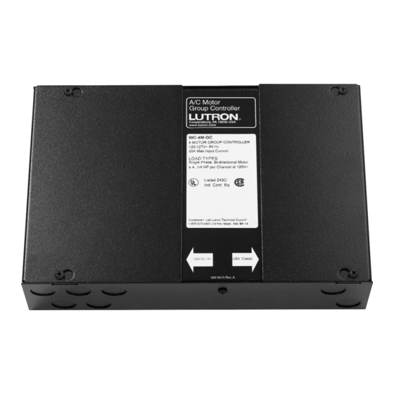
(WC-2M- Load Capacity GC) or up to four motors (WC-4M-GC). Both accept inputs 5 A, 1/4 HP motor load per channel @ 120 V from controls that provide low-voltage, Class 2, dry contact closures. -
Page 3: System Diagram
Treatment Treatment Distribution Panel Line-Voltage Wiring 2 conductors plus ground Line-Voltage 3 Wire AC Motor Wiring 3 conductors plus ground WC-4M-GC Group Controller AC Motor Group Controller Coopersburg, PA 18036 USA www.lutron.com Contact Closure Device WC-4M-GC 4 MOTOR GROUP CONTROLLER... -
Page 4: Determine A Mounting Location
• The unit’s relays will click audibly in normal use. Mount in a location where this is acceptable. • Mount the WC-2M-GC, WC-4M-GC on a dry, flat indoor • The keyholes accept a maximum of 3/16" (5 mm) surface such as an electrical closet wall. -
Page 5: Pre-Installation Motor Wiring Check
Pre-installation Motor Wiring Check Test your wiring before connecting to the Group Controller. Use either a momentary, Single Pole Double Throw (SPDT) switch (as described below) or a motor wiring test kit (available from Lutron). To order the motor wiring test AC Motorized kit, contact Lutron at 1-888-SIVOIA1 (1-888-748-6481) and Window... -
Page 6: Line Voltage Wiring
The recommended tightening torque is 9.0 in-lbs for motors in parallel. line-voltage connections and 10 in-lbs for earth ground • The WC-2M-GC and WC-4M-GC accepts 110-127 V~, connections. 60 Hz. • Run all power feed and motor power wiring through the •... -
Page 7: Configuring The Motor Direction For Open And Close Functions
Each motor channel has a contact closure input terminal block. In addition, the unit has a master control contact The WC-2M-GC and WC-4M-GC accept Class 2, dry closure input terminal block. The master control contact contact closure inputs. The contact closure inputs for this closure input will operate all four motor channels unit may be either momentary or maintained. -
Page 8: Example Of Individual Control
In this wiring example, the stop function is achieved by simultaneously providing a closure on the open and close terminals of the input terminal block. No connection is made to the stop terminal on the input terminal block. WC-4M-GC Group Controller Shown OPTIONS ROLLER STATUS POWER... -
Page 9: Example Of Individual Control (With Dedicated Stop Input)
Example of Individual Control (with dedicated stop input) In this wiring example, the stop function is achieved by providing a closure to the stop terminal of the input terminal block. WC-4M-GC Group Controller Shown OPTIONS ROLLER STATUS POWER OPEN ALL... -
Page 10: Example Of Master Control (With Dedicated Stop Input)
In this wiring example, each master function is achieved by providing a closure to the open, stop, or close terminal of the input terminal block. Activating any closure will affect all motors connected to this Group Controller. WC-4M-GC Group Controller Shown OPTIONS ROLLER STATUS POWER... -
Page 11: Connecting Multiple Group Controllers
See the diagram rated for at least 8 mA, at 30 Vdc. below. This may be used for the individual inputs and/or master control input. WC-4M-GC Group Controller Shown To Additional Group ller Controllers OPTIONS... -
Page 12: Setting The Contact Closure Input Type
Setting the Contact Closure Input Type When operating from contact closure inputs, the WC-2M- GC and WC-4M-GC can accept either momentary or maintained contact closure inputs. See Appendix A on ON = page 13 for a more detailed description Maintained Inputs Momentary Inputs: The unit will accept a momentary closure input of greater than 0.2 seconds to activate the... - Page 13 Appendix A Contact Closure Inputs: Inputs on a single channel and Master Control Maintained Mode Operation When a contact closure is provided to a single input on an individual channel, the Group Controller will energize the In maintained mode, the Switched Live output for a appropriate Switched Live output.
-
Page 14: Troubleshooting
Troubleshooting Symptom Possible Cause Solution AC motor does not move in either • Motor wired to Group Controller Verify motor wiring. direction when manual override improperly. buttons pressed. • Limit switches on motor not set Verify limit switch settings on motor. properly. - Page 15 Notes...
- Page 16 Visit our web site at www.lutron.com Lutron is a registered trademark and RadioTouch is a trademark of Lutron Electronics Co., Inc. © 2002 Lutron Electronics Co., Inc.
Need help?
Do you have a question about the WC-4M-GC and is the answer not in the manual?
Questions and answers