Table of Contents
Advertisement
Available languages
Available languages
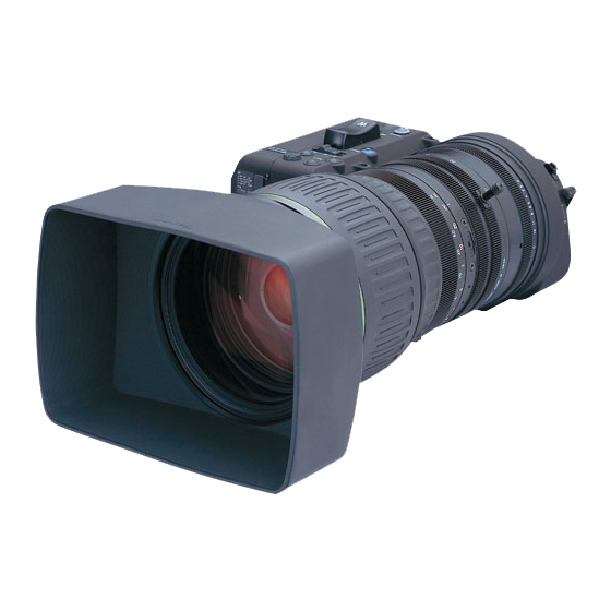
BCTV Zoom Lens
广播电视变焦镜头
HJ40x
HJ40x10B
HJ40x14B
取
扱
説
OPERATION MANUAL
使 用 说 明 书
ご使用の前に必ずこの取扱説明書をお読みください。
なお、取扱説明書は必要に応じてご覧になれるよう大切に保管してください。
Read this operation manual before using the product.
Keep the manual in place for future reference.
在使用本产品之前 , 请务必先仔细阅读本使用说明书。
请务必妥善保管好本书 , 以便日后能随时查阅 ( 保留备用 ) 。
请在充分理解内容的基础上 , 正确使用。
LENSES
明
書
J/E/C
Advertisement
Chapters
Table of Contents

Related Manuals for Canon HJ40x10B


Summary of Contents for Canon HJ40x10B
- Page 1 BCTV Zoom Lens 广播电视变焦镜头 HJ40x LENSES HJ40x10B HJ40x14B 取 扱 説 明 書 OPERATION MANUAL 使 用 说 明 书 ご使用の前に必ずこの取扱説明書をお読みください。 なお、取扱説明書は必要に応じてご覧になれるよう大切に保管してください。 Read this operation manual before using the product. Keep the manual in place for future reference. 在使用本产品之前 , 请务必先仔细阅读本使用说明书。...
- Page 2 FOREWORD Thank you for purchasing the Canon BCTV zoom lens. This operation manual explains the functions and operating instructions for the Canon BCTV zoom lens. It also describes precautions for handling the lens. This operation manual is applicable for the following lens models:...
- Page 3 日 本 語 版 ENGLISH VERSION ……………………… See Page E1 中文版 ....... 请参阅第 C1 页...
-
Page 4: Table Of Contents
目 次 安全にお使いいただくために .............1 1. 標準商品構成 ..................4 2. 各部の名称 .....................5 3. 取付け・接続 ............7 3-1. サポーター・レンズ・三脚の取付け .................. 11 3-2. フードの取付け ............11 3-3. IS 操作ユニットの取付け・接続 4. 操作前の準備 ..............13 4-1. レンズのフランジバック調整 ................13 4-2. アイリスゲイン調整 5. 操 作 ..................14 5-1. ズーム操作 ................. 24 5-2. -
Page 5: 安全にお使いいただくために
安全にお使いいただくために 製品および取扱説明書に記載されている安全に関する警告や注意事項は、 必ず守ってください。 これら危険防止の警告や注意事項にそった取扱いをしない場合、 けがや事故に至る可能性があります。 この取扱 説明書をよく読んで、 十分に理解した上で本製品を正しくご使用ください。 また、 この取扱説明書は必要に応じてご覧になれるよう大切に保管してください。 この取扱説明書の中では、 お客様および他の人々の安全をお守りし、 事故を未然に防止するための警告文や注意 文に以下のシンボルマークと言葉を使用しています。 取扱いを誤った場合に、死亡または重傷を負う恐れがある警告意事 警告 項が書かれています。安全に使用していただくために、必ずこの警 告事項をお守りください。 取扱いを誤った場合に、負傷を負う恐れがある注意事項が書かれて 注意 います。安全に使用していただくために、必ずこの注意事項をお守 りください。 操作する上での注意事項、または推奨事項です。 ここに記載されていることを守らないと、製品が正しく機能しない ※(注) 可能性があります。 また、操作上における有益な情報も記載されています。 取扱いについて 警告 1. 水をかけたり、 濡らしたりしないでください。 万一、 内部に水が入った場合は使用を中止してください。 そ のまま使用すると、 火災や感電の原因となります。 2. - Page 6 ※(注) 1. 修理を行う場合は、 キヤノンマーケティングジャパン(株) 、 お求めになった代理店、 または直接キヤノン (株) へお問い合わせください。 2. 本製品に強い衝撃を与えると故障の原因となることがあります。 3. 本製品は、 防滴構造にはなっておりません。 雨 ・ 雪など、 水滴に直接さらして使用しないでください。 故障 の原因となることがあります。 4. 粉塵の多い場所でのご使用、 またはレンズの着脱には十分ご注意ください。 製品内に粉塵が入ると、 故障の 原因となることがあります。 5. 急激な温度変化を与えますと、 レンズの内部が曇ってしばらくの間使用できなくなることがあります。 曇 り対策処置など十分にご配慮ください。 6. 化学薬品を使用するなど特殊な環境のもとでレンズを使用される場合には、 あらかじめご相談ください。 異常時の対処方法について 警告 万一下記のような異常が発生した場合には、 ただちにレンズをカメラから取り外して、 お求めになった代 理店、...
- Page 7 保管について 注意 1. 使用しないときは、 必ずレンズに付属のキャップやカバーを付けてください。 キャップやカバーなどを 付けない状態で直射日光に当たるとレンズの集光作用により火災の原因となることがあります。 ※(注) 1. 霧や小雨などで湿気を含んだ場合には、 速やかに乾いた布で水分をふき取り、 乾燥剤(できるだけ新し い乾燥剤を使用) とともに、 ビニール袋に入れて密封し、 完全に内部の湿気を除去してください。 カビ や故障の原因となることがあります。 お客様へ 1. お客様の誤った操作に起因する障害については、 当社は、 責任を負いかねますのでご了承ください。 2. 本製品の品質 ・ 機能および取扱説明書に関して、 お客様の使用目的に対する適合性 ・ 市場性などについ ては、 一切の保証をいたしかねます。 また、 そこから生じる直接的 ・ 間接的損害に対しても責任を負いか ねます。 3. 本製品を使用して得られた結果については、 保証いたしかねます。 4.
-
Page 8: 標準商品構成
シール ......................... 1 取扱説明書 (※ 1) : サポーターは仕様などによりレンズに構成されない場合があります。本取扱説明書の構成と取扱 いは、 キヤノン標準のサポーターを使用した場合について記載しています。別途異なるサポーター を使用する場合は、ご使用になるサポーターの取扱説明書をご覧ください。 フード IS 操作ユニッ ト フードキャップ レンズキャップ レンズ本体 ズームレバー ダストキャップ 取扱説明書 サポーター シール (上図は HJ40x10B IASD-V です。機種および仕様により形状は若干異なる場合があります。 ) 仕様により上記付属品以外のアクセサリーが必要になる場合がございます。詳細はお買い上げの販売 店までお問合せください。 ※(注) : 1) 常温下に保管してください。 2) 急激な温度変化を与えますと、レンズの内部が曇ってしばらくの間使用できなくなることが あります。 曇り対策処置など十分にご配慮ください。 3) 強い衝撃や振動をレンズに与えないようにしてください。... -
Page 9: 各部の名称
2. 各部の名称 (上図は HJ40x10B IASD-V です。 機種および仕 様により形状は若干異なる場合があります。 ) 9 アイリスサーボ / マニュアル切替えスイッチ 1 フード アイリス操作をマニュアル、またはサーボに切 レンズのゴーストやフレヤーを防ぎます。 り替える場合にこのスイッチを使用します。 2 フードロックノブ 10 “Memo” スイッチ フードをレンズに固定するノブです。 このスイッチとほかのスイッチ (Shtl, Frame,ズー 3 ディップスイッチ ム操作スイッチ)を押して、ズームポジション 各種設定用のディップスイッチがあります。 やズームスピードの設定を行います。 4 IS ON/OFF スイッチ 11 ズームシーソースイッチ IS(像ブレ防振機構)の ON/OFF 操作を行いま サーボズームをする場合に使用します。深く押 す。 すほど、ズーム速度が速くなります。 5 最高ズームスピード調整ボリューム 12 “RET” スイッチ ズームシーソースイッチでズーム操作を行うと... - Page 10 17 フランジバックロックネジ 25 レンズケーブル フランジバック調整リングを固定するネジです。 このケーブルを通して、電源や信号をカメラか らレンズに送ります。 18 位置決めピン 26 ズームリモート用コネクター(8ピン) レンズの取付け位置を決めるピンです。 ズーム操作用コントロールアクセサリー (8 19 マクロボタン ピン)を接続します。 至近距離より近い被写体に近づいて接写したい 27 ズームリモート & フォーカスリモート用 場合、このボタンを使用します。 コネクター(20 ピン) 20 エクステンダー切替えレバー ズームまたはフォーカス操作用コントロール このレバーの操作により内蔵エクステンダー アクセサリー(20 ピン)を接続します。 を操作します。 28 IS リモート用コネクター 21 フォーカスリング マニュアルでフォーカス操作をする場合に使用 IS 操作ユニットを接続します。 します。 29 ズームサーボ / マニュアル切替えノブ 22 ズームリング ズーム操作をマニュアルまたはサーボに切り 替える場合にこのノブを使用します。 マニュアルでズーム操作をする場合に使用しま 30 フォーカスサーボ / マニュアル切替えノブ す。...
-
Page 11: 取付け・接続
3. 取付け・接続 3-1. サポーター・レンズ・三脚の取付け 本レンズには、 専用のサポーター SUP-300 を用意しています。レンズおよびカメラ保護のため、 必ず、 専用のサポーターをご使用ください。レンズ、カメラ、サポーターおよび三脚の取付け手順は以下の ようになります。 ① サポーターを三脚に取り付ける。 (A) 項 ▼ ② カメラをサポーターに取り付ける。 (B) 項 ▼ ③ レンズをカメラに取り付ける。 (C) 項 ▼ ④ バランスを調整する。(D) 項 の三脚への取 (A) サポーター 付け トライポッ ドアダプター サポーター本体 (カメラメーカー供給品) 1. サポーター本体の底面に三脚の V ウェッジ板を 取り付けます。V ウェッジ板取付け用コマには、 サポーターへ取り付ける... - Page 12 2. トライポッドアダプターを以下の手順でサポー ターに取り付けます。 (トライポッドアダプターはカメラメーカー供給 カメラ取付けネジ 品です。カメラの取扱説明書も併せてご覧くだ さい。 ) 2-1. トライポッドアダプターにある三脚用ネ ジ穴に、2つあるカメラ取付けネジ(3/8- UNC) を差し込み、それぞれのカメラ取付 カメラ取付けノブ けノブを回して、これら2つのネジを締 カメラ取付けロック ノブ め付けます。 2-2. さらに、ゆるみ防止のため、カメラ取付け ロックノブを回して締め付け固定します。 サポーターを 3. 三脚のカムヘッドのパン、チルト機構およびシ カムヘッ ドに取り付ける ステム重心ロックハンドルがロックされている ことを確認したあと、前 1.,2. 項で V ウェッジ板 とトライポッドアダプターを取り付けたサポー ターをカムヘッドに取り付けてください。 注意: サポーターを取り付ける前に、三脚またはペデスタルの取扱説明書をよくお読みいただ き、カムヘッドのパンおよびチルト機構のロックと解除の方法をよくご理解してから V ウェッジ板をカムヘッドに据え付けてください。もし、カムヘッドのパンおよびチルト 機構がロックされていないと、カメラ、レンズ、およびサポーターを落下させて破損さ せたり、落下が起因でけがを負う危険があります。ご注意ください。...
- Page 13 (C) レンズの取付け 1. 上下調整ロックつまみを緩め、レンズ支持台を レンズをカメラに取り付ける 下まで下げておきます。 1× 2× 2. レンズを以下の手順でカメラに取り付けます。 2-1. カメラ側のバヨネットマウントを反時計 方向に回転させ、保護キャップを外して ください。 2-2. レンズのダストキャップを反時計方向に 回転させ、外してください。 2-3. レンズのマウント面にある位置決めピン をカメラマウント面にある溝に合わせて からレンズをカメラマウント面に密着さ レンズ支持台 せてください。 2-4. カメラ側のバヨネットリングをレンズ側 取付けつまみ より見て時計方向に回してレンズを固定 上下調整 ロックつまみ してください。 注意: この状態においてはマウント部だけでレ ンズを支えているため、少量の力でマウ ント接続部を痛める恐れがあります。こ 前後調整ロックつまみ れ以降、 特に取付け作業が完了するまで、 レンズには外部から力を加えないように してください。 位置決めピン 2-5.
- Page 14 5. 取付けつまみをレンズ本体に固定することができたら、 上下調整ロックつまみ、 および前後調整ロッ クつまみを締め付け固定します。 ※(注) : ロックつまみを締め付ける際は、 2. 項でカメラにレンズを装着した状態を適切な位置とし、 レンズを押し上げたり、引いたりして位置を無理に動かしてしまうような取付けを行わな いようご注意ください。 (D) バランス調整 1. カムヘッドのパンおよびチルト機構を緩めて三脚 のパンバーを持つなどして重心などのバランスを 確認してください。 2. システム重心ロックハンドルを解除すると、“レン 解除 ズ、カメラ、サポーター” 一式 を三脚に取り付け システム重心 たまま、前後に移動させることができます。重心 ロックハンドル 位置がずれている場合、重心位置を調整してくだ さい。 1× 2× 3. 重心位置の調整ができたら、システム重心ロック ハンドルをロックしてください。また、システム 重心ロックハンドルは、手前に引くとロック状態 を保ったままハンドルを360°任意の方向に変 えることができます。このあとの撮影中などに、 パンバー 不意に触れることのない位置に設定してくださ い。 ハンドル位置の調整...
-
Page 15: フードの取付け
3-2. フードの取付け フードロック ノブ 1. レンズが工場から出荷されるときは、レンズ キャップが取り付けてあります。最初にこのレ ンズキャップを取り外してください。 2. フードをレンズに取り付け、フードとレンズ鏡 筒についている各々の指標点を合わせ、フード ロックノブを締めてください。 レンズ鏡筒 3. フードキャップをフードから外してください。 指標点 フード ※(注) : 取り外したフードキャップおよびレンズキャップは、なくさないよう大切に保管して ください。 3-3. IS 操作ユニットの取付け・接続 IS 操作ユニットとは、イメージスタビライザー(像ブレ補正機構)の ON/OFF 操作を行うスイッチユ ニット部とその動作状態を示す表示ユニット部から構成され、操作しやすいお好みの場所に取り付け てイメージスタビライザーのリモートコントロールを可能にするものです。 (IS: Image Stabilizer の略) IS 操作ユニットを以下の手順で取付け・接続してください。 1. IS 操作ユニットのコネクターをレンズ本体ドライブユニット底面の IS リモート用コネクター へ接続してください。... - Page 16 ※(注) : 1) レンズ本体のドライブユニット上にも IS ON/OFF スイッチと IS 動作状態表示 LED が装備されていますので、IS 操作ユニットとの併用が可能です。 2) IS 動作状態表示が不要の場合には、IS 操作ユニットから表示ユニット部を取り外 してスイッチユニット部のみを接続して使用することも可能です。 (下図参照) IS ON/OFFスイッチ 面ファスナー ISリモート用コネクター 面ファスナー レンズ本体 3) イメージスタビライザーの操作方法につきましては、5-4. イメージスタビライザー の操作をご覧ください。...
-
Page 17: 操作前の準備
4. 操作前の準備 1. レンズのフランジバック調整 ズームレンズの結像面と TV カメラの結像面が合致していないと、ズーム操作を行ったときフォーカ スが合わなくなります。下記の手順でレンズのフランジバックを調整してください。 1. 適当と思われる距離(5 ~ 7m 位)に被写体を定め エクステンダー切替えレバー ます。コントラストのはっきりしたものを被写体と F.B.調整リング して利用すると 作業がしやすくなります。 2. エクステンダー切替えレバーを 1x にします。 3. アイリス操作でレンズの絞りを開放(オープン)に フランジバック します。 ロックネジ 4. レンズのズームを望遠端(テレ)いっぱいにします。 5. フォーカス操作で焦点(ピント)を合わせます。 6. レンズのズームを広角端(ワイド)いっぱいにします。 7. レンズのフランジバックロックネジを緩め、F.B. 調整リングを回して焦点(ピント)を合わせます。 8. 4. ~ 7. の操作を2, 3回繰り返して、ズーム両端での焦点(ピント)を合わせます。 9. -
Page 18: ズーム操作
5. 操 作 5-1. ズーム操作 (A) マニュアルズーム操作 レンズ本体のドライブユニット底面部にあるズーム ズームサーボ/マニュアル切替えノブ サーボ / マニュアル切替えノブを “MANU.” 側にして ください。 注意:“SERVO” 側にしたまま無理に マニュアル ズーム操作を行うと、機構を破損させる 恐れがあります。必ず “MANU.” 側にして からマニュアルズーム操作を行ってくださ い。 ● レンズ本体のズームリング(またはズームレバー)による操作 レンズ本体のズームリング(またはズームレバー)を 回してズーム操作を行います。 広角 カメラ側から見て 時計方向に回すと広角(ワイド)側へ 望遠 反時計方向に回すと望遠側(テレ)側へ ズームします。 ズームリング ズームレバー (B) サーボズーム操作 レンズ本体のドライブユニット底面部にあるズーム ズームサーボ/マニュアル切替えノブ サーボ / マニュアル切替えノブを “SERVO” 側にして ください。... - Page 19 サーボズーム基本操作 ● ドライブユニット上のズームシーソースイッチによる操作 ドライブユニット上面部のズームシーソースイッチを 押してズーム操作を行います。 ズームシーソースイッチ ズームシーソースイッチの “T” 側を押すと望遠(テレ)側へ “W” 側を押すと広角(ワイド)側へ ズームされます。 スイッチの押し込み具合により、ズームスピードが変 わります。深く押すほど、ズームスピードが速くなり ます。 ● ズームシーソースイッチを押したときのズーム速度の変更 最高ズーム速度は、レンズドライブユニットの上面に 最高ズームスピード調整ボリューム ある最高ズームスピード調整ボリュームを回すことに より変化させることができます。 このボリュームを時計方向いっぱいに回すと最高ズー ム速度が最大になり、反時計方向いっぱいに回すと最 小になります。 サーボズーム応用操作 新操作ユニット「Digital Drive」により従来のサーボズーム基本操作に加え、新しいサーボズーム操作 が追加されています。主な機能は次の通りです。 ● 機能 1. シャトルショット ……………… 2 つの画角を頻繁に切り替えて撮影する際などに便利 な機能です。 ● 機能 2. フレーミングプリセット ……… リハーサルなどで決めた画角とズームスピードを容易 に再現できます。...
- Page 20 ● 機能 1. シャトルショット “Shtl” スイッチを押すだけで最高速度で、 あらかじめ記憶させたズームポジション(シャトルメモリー ポジション)にズームし、“Shtl” スイッチを離すと元のズームポジションに戻ります。すなわち、2 ヶ 所のポジションを高速で切り替えることができます。 “Shtl”スイッチ 1. シャトルメモリーポジションの設定 ズームシーソースイッチ 1-1. 任意のポジションにズーミングする。 1-2. “Memo” スイッチを押しながら “Shtl” スイッチを押す。 (シャトルメモリーポジ ション記憶完了) “Memo”スイッチ ※(注) : このシャトルメモリーポジション位置は「機能 2. フレーミングプリセット」の記憶位置と は別のものです。また、このとき、記憶されたズームポジションは電源 OFF 後も記憶され ています。 2. シャトルメモリーポジションへの移動 “Shtl” スイッチを押し続けているとシャトルメモリーポジションへ最高速でズーム移動して停止し ます。この “Shtl” スイッチを押している間は、この設定ズームポジションを維持します。 3.
- Page 21 機能1. シャ トルショッ トの操作イメージ (凡例) ズーム位置 シャトルメモリーポジション (設定ズームポジション) への移動 ● 操作方法 “Shtl”スイッチを押しつづけるとシャ トルメモリーポジションへズームします。 ● このポジションへ到達したあとも、 “Shtl”スイッチを押している間はこの位置を維持します。 シャ トルメモリーポジション 復帰ポジション “S h tl”スイッチを押しつづける Shtl”スイッチを離すと復帰ポジションへ戻ります。 ● 復帰ポジション シャ トルメモリーポジション 押しつづけた“ S ht l”スイッチを離す そ の 他 ● 下記のいずれかの操作をすることで、 シャ トルメモリーポジションへの移動が解除できます。 シャ トルメモリーポジションに到達する前に、 “ Shtl ” スイッチを離すと復帰ポジションへ自動 ●...
- Page 22 ● 機能 2. フレーミングプリセット “ Frame” スイッチを押すことで適当な位置から、あらかじめ記憶させたズームポジション(フレーミ ングメモリーポジション) にズームすることが出来ます。フレーミングメモリーポジションまでのズー ムスピードは、 「最高速」または「機能 3. スピードプリセットで設定したズームスピード」のいずれ かに切り替えることができます。 1. フレーミングメモリーポジションの設定 “Shtl”スイッチ 1-1. 任意のポジションにズーミングする。 ズームシーソースイッチ 1-2. “Memo” を押しながら “Frame” を押す。 (フ レーミングメモリーポジション記憶完了) ※ (注) : このフレーミングメモリーポジション記憶 位置は「機能 1. シャトルショット」の記 “Memo”スイッチ 憶位置とは別のものです。また、このとき 記憶されたフレーミン グメモリ ー ポジ ションは電源...
- Page 23 機能2. フレーミングプリセッ トの操作イメージ (凡例) ズーム位置 フレーミングメモリーポジションへの移動 ● 操作方法 “Frame スイッチを押すとフレーミングメモリーポジションへ向かって移動し、 メモリーポジ ● ションへ到達するとそこで停止します。 移動時のズーム速度はスピードモード切替えレバーが 「Fast」 の位置にあれば最高スピードに、 「Pre」 の位置にあれば記憶させたスピードになります。 スピードモード切替え レバーの設定位置 フレーミングメモリーポジシ ョン 任意のポジション −最高スピードで移動− 「Fast 」 “Fra me ”スイッチを押す −記憶させたスピードで移動− 「Pre」 “Fra me ”スイッチを押す そ の 他 ● 下記のいずれかの操作を行うことで、 フレーミングメモリーポジションへの移動解除または操作切 替えができます。...
- Page 24 ● 機能 3. スピードプリセット あらかじめ記憶させたズームスピードおよびズーム方向(望遠側または広角側)をスイッチを押すだ けで何度も再現することができます。ただし、 この機能を使用するには “RET” スイッチまたは “VTR” スイッチにこの機能を割り当てる設定が必要となります。 1. スピードプリセット機能のスイッチ設定 この機能を使用したい場合は、専用スイッチは無いので、“RET” または “VTR” スイッチに機能 の割付け設定が必要となります。 割付け方法はドライブユニットの前面にあるディップスイッチ8ピン ( 上側 ) を下記のように設定 します。 ズームシーソースイッチ “RET” に割り付ける場合 “RET”スイッチ → Dip 1:OFF,Dip 2:ON “VTR” に割り付ける場合 → Dip 3:OFF,Dip 4:ON “RET” を元の機能に戻す場合 “Memo”スイッチ...
- Page 25 ※(注) : 「機能 1. シャトルショット」のようにスイッチを押し続けなくても、一度押しただけでズー ム端まで移動し、復帰ポジションも設定されません。 4. スピードプリセットでの移動中の解除または切替え スピードプリセットでの移動中、下記のいずれかの操作により移動が解除されます。 ● 設定したスイッチ(“RET” または “VTR”)をもう一度押すと、移動が停止します。 ● ズームシーソースイッチによる操作を行う。 ● “Shtl” スイッチによる操作を行う。 ● “Frame” スイッチによる操作を行う。...
- Page 26 機能3. スピードプリセッ トの操作イメージ (凡例) ズーム位置 スピードプリセッ ト機能 ● 操作方法 スピードプリセッ ト機能を設定したスイッチ (”RET または”VTR スイッチ) を押すと記憶させた ” ” ● スピードで記憶させた方向に向かってズームし、 ズーム端 (望遠または広角端) で停止します。 ズーム端 任意のポジション −記憶させたスピードで移動− 設定したスイッチを押す そ の 他 ● 下記のいずれかの操作をすることで、 ズーム移動を解除または操作切替えができます。 スピードプリセッ ト機能を設定したスイッチ (”VTR または”RET スイッチ) をもう一度、 ” ” ●...
- Page 27 Digital機能スイッチ一覧 “ S h t l ”スイッチ ・ “Shtl”を押し続けるとシャ トルメモリーポジシ ョン へ移動します。 このポジションへ到達したあとも、 “Shtl”を押してい る間はこの位置を維持します。 シャ トルメモリー 復帰ポジション ポジション “Shtl”押しつづける ・ “Shtl”を離すと復帰ポジションへ戻ります。 シャ トルメモリー 復帰ポジション ポジション 押しつづけた“S htl”を離す そのほか、 詳しい機能については 「 機能1. シャ トル ● ショッ ト」 をご覧ください。 “Memo”スイッチ このスイッチと他のスイッチを押して、 設定ズーム ポジションやズームスピードの設定を行います。...
-
Page 28: フォーカス操作
5-2. フォーカス操作 ● レンズ本体のフォーカスリングによるマニュアルフォーカス操作 マニュアルフォーカス操作を始める前に、フォーカス サーボ / マニュアル切替えノブが “MANU.” 側になっ ていることを確認してください。万一、切替えノブが フォーカスサーボ/マニュアル切替えノブ “SERVO” 側になっていたら “MANU.” 側に切り替え てください。 注意:“SERVO” 側にしたまま無理にマニュアルフォーカス操作を行うと、機構を破損させる 恐れがあります。必ず “MANU.” 側にしてからマニュアルフォーカス操作を行ってくだ さい。 カメラ側より見てフォーカスリングを 至近 時計方向に回すと至近側の被写体に 反時計方向に回すと無限側の被写体に 焦点(ピント)が合います。 無限 フォーカスリング... -
Page 29: アイリス操作
5-3. アイリス操作 アイリス操作は、アイリスサーボ / マニュアル切替えスイッチによりオート / マニュアルどちらかの操 作が選択できます。 “A”(オート) :カメラ指令信号によるオートアイリス操作 “M”(マニュアル) :レンズ本体のアイリスリングによるマニュアル操作 ● マニュアルアイリス操作 アイリスサーボ / マニュアル アイリスサーボ / マニュアル切替えスイッチを “M” 側にして 切替えスイッチ ください。 ● レンズ本体のアイリスリングを手動で回してのアイリ ス操作 クローズ カメラ側から見て時計方向にアイリスリングを回すことによ りアイリスが絞り込まれ、ビデオレベルが下がります。反時 オープン 計方向に回すとアイリスが開き、ビデオレベルが上がります。 アイリスリング ● アイリス瞬時オートスイッチ アイリス瞬時オートスイッチ アイリスをマニュアル操作で撮影中にアイリス瞬時オートス イッチを押すと、押している間だけ “A”(オート)アイリス 状態になります。 一時的に適正露出を得たい場合などにご使用ください。... -
Page 30: イメージスタビライザーの操作
5-4. イメージスタビライザーの操作 本レンズに搭載されていますイメージスタビライザー(像ブレ補正機構)は、輸送時の衝撃から防振 光学系を保護するためのメカロック機構を備えています。 イメージスタビライザーを使用可能とするためには、まずこのロック状態を解除し、防振光学系駆動 回路に電源を供給する必要があります。 ロックが解除されたイメージスタビライザーには以下の 2 つの状態が存在しますので、必要に応じて、 これらの状態を切り替えて使用します。 防振光学系が像ブレ補正を行っている作動状態 ………………… IS ON 防振光学系が電気的に光軸中心に保持された待機状態 ………… IS OFF (A) メカロックの解除方法 カメラからの電源投入直後のイメージスタビライザー “IS POWER OFF”スイッチ は、メカロック状態になっています。マウント横のカ メラ面側にある "IS POWER ON" レバーは、メカロッ クを解除すると同時に防振光学系駆動回路に電源を供 給するためのスイッチの役割を兼ねています。 "IS POWER ON" レバーを水平状態から反時計回りに、 レバーがほぼ垂直になるまで回転させます。この状態 で手を離せばレバーがロックされ、イメージスタビラ イザーが使用可能となります。 (このとき、レンズ本 “IS POWER ON”レバー... - Page 31 (B) メカロックの実行方法 本レンズに搭載されていますイメージスタビライ “IS POWER OFF”スイッチ ザーは、レンズへの電源供給が断たれますと自動 的に防振光学系をメカロックするようになってい ますので、撮影終了時に手動でメカロックを行う 必要はありません。 また防振光学系は正確に光軸中心位置でメカロッ クするようになっていますので、防振機能を必要 としない場合は防振光学系をメカロックして撮影 が可能です。このため防振光学系駆動回路のみ の電源を断つ "IS POWER OFF" スイッチを "IS “IS POWER ON”レバー POWER ON" レバーの傍らに設けています。必要 がある場合、このスイッチを押してメカロックさせてください。 防振光学系が静止している場合(待機状態)でも防振光学系駆動回路では微弱な電力を消費していま すのでメカロックすることにより節電が可能です。 なお、レンズへの電源供給が断たれたとき、または "IS POWER OFF" スイッチを押してメカロックに なった場合は、"IS POWER ON" レバーは自動で水平位置に移動します。 注意 : 撮影中、 意図的に防振光学系をメカロックする場合は、 必ず "IS POWER OFF" スイッ チを使用してください。故障の原因となりますので、"IS POWER ON"...
- Page 32 (C) イメージスタビライザーの像ブレ補正操作 メカロックを解除したイメージスタビライザーには以下の 2 つの状態が存在しますので、必要に応じ て、これらの状態を切り替えて使用します。 防振光学系が像ブレ補正を行っている作動状態 ………………… IS ON 防振光学系が電気的に光軸中心に保持された待機状態 ………… IS OFF (C-1) 作動と待機の切替え操作 作動状態と待機状態の 2 つの状態は、IS 操作ユニットまたはレンズ本体ドライブユニット上の IS ON/OFF スイッチにて切替え操作を行います。IS ON 時にはともに LED が緑色点灯して、その作動 中を表示します。IS OFF 時は、IS 操作ユニット側の LED は消灯、ドライブユニット上の LED は オレンジ色に点灯します。 (ドライブユニット上の LED の点灯(緑 / オレンジ)は、防振光学系駆 動回路に電源が供給されていることを示しています)...
- Page 33 (C-3) イメージスタビライザーの動作環境の選択 IS ON/OFF スイッチの挙動(スイッチモード)およびイメージスタビライザーの像ブレ補正方向は、 工場出荷時の初期設定では、次のように設定されています。 スイッチモード…スイッチを押すたびに ON と OFF が切り替わるオルタネイト動作(ALT) 補正方向…………水平(H)+垂直(V)の両方向に対して実行 ただし、使用環境やお好みに応じて次のように設定して使用することも可能です。 スイッチモード…スイッチを押している間のみ ON にするモーメンタリー動作(MON) 補正方向…………垂直(V)のみに対して実行 防振方向選択 スイッチモード選択 IS ON/OFF IS 機能操作 (10 ピン DIP SW9) (10 ピン DIP SW8) スイッチ操作 IS スイッチを押すたびごとに H, V 全方向の 押して離すごとに 像ブレ補正 作動⇔待機 の繰り返し (水平+垂直) 押している間...
- Page 34 イメージスタビライザーの状態と切替え / 設定スイッチの関係 ロック状態 (輸送時非通電状態) カメラ電源OFFで自動ロック IS POWER ON レバー IS POWER OFF スイッチ ロック解除状態 (撮影時通電状態) 待機状態 作動状態 補正方向 (H+V / V) 補正特性 (STD / MAX) 各種 動作環境設定スイッチ IS ON / OFF スイッチ SW MODE (ALT / MOM) : スイッチ操作 ※(注) : ロックを解除したときにイメージスタビライザーが作動・待機のどちらの状態となるかは、 IS ON/OFF スイッチの設定モードにより異なり、...
-
Page 35: エクステンダー操作
5-5. エクステンダー操作 本レンズには、2 倍エクステンダーが内蔵されています。エクステンダー操作により、レンズの焦点 距離を 2 倍に伸ばすことができます。ただし、エクステンダーを使用しますと、その変倍分だけ F ナ ンバーが低下しますのでご注意ください。 H J40x10B IASD-V ● マスターレンズ 2 倍エクステンダー使用時 焦点距離 10 ~ 400 mm 20 ~ 800 mm 最大口径比 1 : 2.0 at 10 ~ 220 mm 1 : 4.0 at 20 ~ 440 mm 1 : 3.65 at 400 mm 1 : 7.3 at 800 mm H J40x14B IASD-V... -
Page 36: マクロ操作
最短で 1 cm(ワイド端、マクロ位置)まで近付いて接写できます。 ● 操 作 レンズ本体後部にあるマクロリングを回して、マクロ操作を行います。 マクロボタンを押してロックを解除し、押したままの状態でカメラ側から見て時計方向にマクロリン グを回すとマクロ撮影ができます。 1. マニュアルまたはサーボによりズームを広角端 (ワイド)いっぱいにしてください。 2. マクロボタン(マクロリング)でピントを合わ せてください。 マクロリング マクロボタン ● マクロ撮影距離と被写体範囲 HJ40x10B IASD-V ズーム位置 マクロボタン 至近距離 被写体範囲 *1 10 mm ロック 280 cm 248.4 x 129.7 cm 通常撮影 400 mm ロック... - Page 37 ● マクロ撮影応用例 ..多点フォーカス撮影について マクロ撮影の状態で、 ズーミングして焦点距離を変えていくと、 ピントの合う位置も変化していきます。 この特性を利用し、ズーム操作だけで、同一カット内でピントの合う位置をずらしていく特殊技法が 多点フォーカス撮影です。 撮影の手順は次のとおりです。 1. 遠方の被写体にズームアップし、通常のフォーカス操作でピントを合わせます。 2. ズームを広角(ワイド)側に引いて、近距離の被写体にマクロ操作でピントを合わせます。 3. マクロボタンを 2. の状態にしたまま、再度、遠方の被写体にズームアップし、通常のフォー カス操作でピントを合わせます。 手順 1. ~ 3. でセット完了です。 ズームを広角端にしてから、その点よりズームを望遠端に操作すると、“手前の被写体から連続でピン トの合う位置が移動して、ズームアップされたいちばん遠方の被写体までピントが合う” 変化のある 撮影ができます。...
-
Page 38: Vtr スイッチ、Ret スイッチ操作
5-7. VTR スイッチ、RET スイッチ操作 ● “VTR” スイッチ VTR スイッチを押すと VTR が作動し始めます。もう “VTR”スイッチ 一度 VTR スイッチを押すと VTR の作動がストップし ます。 ● “RET” スイッチ “RET”スイッチ RET スイッチを押している間、ビューファインダー 上にリターンビデオが写し出されます。 ※(注) : VTR スイッチまたは RET スイッチにスピードプリセット機能やその他の機能を割り付けて ある場合は、5-8. 項を参照してそれぞれ本来の機能が働くように設定し直してください。... -
Page 39: ディップスイッチの設定
5-8. ディップスイッチの設定 レンズ本体のドライブユニット前面のゴム ディップスイッチ(8ピン) キャップ下に各種設定用のディップスイッチが (上側) あります。 − − Shtl ON ON ON − − ON − − Shtl ON ON ON − − ON Shtl ON ON Frm ON ON ディップスイッチ(10ピン) (A) ディップスイッチの設定機能 IRIS MH ON SPARE ... - Page 40 (B) ディップスイッチの設定手順 1. 通常、ゴムキャップが付いています。設定前に、このゴムキャップを取り外してください。 2. 各種の機能設定は下記表のようになっています。ご希望の設定にディップスイッチをセットして ください。なお、スイッチはレンズ正面側から見て右側が ON, 左側が OFF となっています。 3. 設定が完了したら、ゴムキャップを元に戻してください。 各種設定項目 ディップスイッチ設定 機能の選択 送り返し(RET) 1 : OFF 2 : OFF シャ トルショッ ト(Shtl) 1 : ON 2 : ON “RET”スイッチへの機能割付け フレーミングプリセッ ト(Frame) 1 : ON 2 : OFF スピードプリセッ...
-
Page 41: ズームモード調整
5-9. ズームモード調整 ズームシーソースイッチによるサーボズームの際、 スイッチを深く押すほど、ズームスピードが速くな ります。 また、最高ズームスピード調整ボリュー ムにより、この最速ズーム速度を変化させることが できます。 (サーボズーム基本操作をご覧ください。 ) ズームモード調整 さらに、最高ズームスピード調整ボリュームによる トリマー 変化分の調整をズームモード調整トリマーで可変さ せることができます。 1. レンズ本体のドライブユニットの前面のゴム キャップの下にズームモード調整トリマーがあります。通常、ゴムキャップが付いています。設 定前に、このゴムキャップを取り外してください。 2. ズームモード調整トリマー(トリマー横のシールに “Z.MODE” と表示)を小型ドライバーなどで 回してください。 時計方向に回すとズームスピードが速くなり、反時計方向で遅くなります。 この調整で、 下図における 「a. ズームモード調整トリマーによる変化分」 を変化させることができます。 また、最高ズームスピード調整ボリュームによる変化は「b. 最高ズームスピード調整ボリュームによ る変化分」になります。 ただし、 “サーボズーム応用操作項” の「機能 1. シャトルショット」 、 「 機能 2. フレーミングプリセット」 の最高速度はズームモード調整トリマーの調整位置にかかわらず、常に最高速度で移動します。... -
Page 42: 製品仕様
127 mm ピッチ 0.75 ( レンズ鏡筒 ) ズームスピード Max. 1.5 ± 0.2 s フォーカススピード 1.8 ± 0.2 s アイリス カメラよりコントロール マウント バヨネットマウント 所要入力電圧 標準 DC12V(10 ~ 17V) 消費電流 最大 600 mA 質 量 約 5.4 kg(HJ40x10B) 約 5.45 kg(HJ40x14B) 使用環境条件 温 度 :-20℃より +45℃の範囲 相対湿度 :5%RH より 95%RH の範囲(結露を生じないこと)... - Page 43 ENGLISH VERSION...
- Page 44 Canadian Radio Interference Regulations CAN ICES-3(B)/NMB-3(B) We, Canon Inc., in Japan and CANON EUROPE LTD., in U.K., confirm that the BCTV zoom lens is conformity with the essential requirements of EC Directive(s) by applying the following standards: EN55032 and EN55103-2...
- Page 45 CONTENTS GENERAL SAFETY INFORMATION ............E1 1. STANDARD COMPOSITION OF THE LENS ..........E4 2. NOMENCLATURE ..................E5 3. MOUNTING AND CONNECTIONS 3-1. MOUNTING THE SUPPORTER, LENS, AND TRIPOD ..........E7 3-2. MOUNTING THE HOOD ON THE LENS ..............E10 3-3. MOUNTING AND CONNECTING THE IS OPERATION UNIT ......... E11 4.
-
Page 47: General Safety Information
GENERAL SAFETY INFORMATION The safety warnings and cautions provided on the product or in this operation manual must be observed. Failure to observe these warnings and cautions may result in injury or accident. Read this operation manual carefully to familiarize yourself with its contents and ensure that you can operate the product properly. - Page 48 5. Take measures to avoid sudden changes in temperature where the lens is used, which may prevent operation temporarily if condensation forms in the lens. 6. Before use in particular environments, such as places where chemical products are used, contact your Canon representative.
- Page 49 For further information on repairs, maintenance, or adjustments not mentioned in this operation manual, contact your Canon dealer or your Canon sales representative. 6. Note that Canon may be unable to undertake servicing or repair of a product if it is modified without consulting Canon or your Canon sales representative.
-
Page 50: Standard Composition Of The Lens
Operation Manual Supporter Sticker (The above drawing shows the HJ40x10B IASD-V. Shapes of lens may be slightly different depending on the models and the specifications.) Accessories other than those mentioned above may be required depending on the specifications of your unit. -
Page 51: Nomenclature
2. NOMENCLATURE (This drawing shows the model HJ40x10B IASD-V. Shapes of lens may be slightly different depending on the models and the specifications.) Hood Iris Operation Change-over Switch This hood is used to cut or reduce ghosting / Slide this switch to change from manual to servo flaring. - Page 52 16 IS Power Off Switch 25 Lens Cable Use this switch to turn off the power supply to Power and signals are sent to the lens from the camera head through this cable. the image stabilizer. 26 Connector for Remote Zoom Control (8pin) 17 F.B.
-
Page 53: Mounting And Connections
Supporter camera manufacturer) 3/8-UNC and 1/2-UNC mounting screw holes. (The V-wedge board is not supplied by Canon.) The V-wedge board mounting tap can be moved forwards or backwards, and the lock handle for the system center of balance can be locked or unlocked Mount by Supporter by turning in the following directions. - Page 54 2. Mount the tripod adapter on the supporter using the procedure below. (The tripod adapter is supplied by the camera manu- Camera Mounting Screw facturer. Be sure to also refer to the camera op- eration manual when performing the mounting procedure.) 2-1.
- Page 55 (C) MOUNTING THE LENS 1. Loosen the vertical adjustment lock knob, and then Mount the lens on the camera lower the lens support. 2. Use the procedure below to mount the lens on the 1× 2× camera. 2-1. Turn the bayonet mount of the camera counter- clockwise, and then remove the protective cap.
-
Page 56: Mounting The Hood On The Lens
The dedicated supporter SUP-300 does not always support some cameras. For more details, be sure to direct your inquiries to Canon. Also, if you like to use a supporter other than SUP-300, be sure to direct your inquiries to Canon. -
Page 57: Mounting And Connecting The Is Operation Unit
3-3. MOUNTING AND CONNECTING THE IS OPERATION UNIT The IS operation unit is an accessory consisting of a switch unit for turning the image stabilizer (IS) on and off and a display unit indicating the operating status. It can be mounted in any location that allows easy op- eration for performing remote control of the image stabilizer. -
Page 58: Preparation
4. PREPARATION 4-1. BACK FOCUS ADJUSTMENT OF THE LENS If the relationship between the image plane of the lens and the image plane of the television camera is incorrect, the object goes out of focus when the lens is zoomed. Follow the procedure below to adjust the flange back of the lens. -
Page 59: Operation
5. OPERATION 5-1. ZOOM OPERATION (A) MANUAL ZOOM OPERATION Set the zoom operation change-over knob at the bot- tom of the lens drive unit to the MANU. position. Zoom Operation Change-over Knob CAUTION: The zoom mechanism can be dam- aged if the lens is forced to perform manual zoom while the lens is set to the SERVO side. - Page 60 Servo zoom operation with the zoom rocker seesaw ● The zoom can be operated by pressing the zoom rocker seesaw located on the top of the lens drive Zoom Rocker Seesaw unit. Press T to zoom in (to Telephoto-end). Press W to zoom out (to Wide-end). The zoom speed changes according to how far down the rocker seesaw is pressed.
- Page 61 Function 1. Shuttle-Shot ● By simply pressing the Shtl button, you can zoom to a shuttle memory position (preset zoom position) at the maximum speed. When the Shtl button is released, the zoom returns to the original position. In other words, this allows the zoom to shuttle between two zoom positions (shuttle memory and original positions) at the maximum speed.
- Page 62 Function 1. Shuttle Shot Operation Diagrams (Example) Zoom Position Basic Movement of the Shuttle Shot Operation ● Operation While the Shtl button is held down, the zoom moves toward the shuttle memory position (preset zoom ● position) at the maximum speed. Once the zoom reaches to this point, the zoom stops and stays there, so long as the Shtl button is held down.
- Page 63 Function 2. Framing Preset ● Pressing the frame button allows you to zoom to a framing memory position (preset zoom position) from any zoom position. The zoom speed to the framing memory position can be chosen as either the maximum speed or the preset zoom speed (See function 3).
- Page 64 Function 2. Framing Preset Operation Diagrams (Example) Zoom Position Basic Movement of the Framing Preset Operation ● Operation When the frame button is pressed, the zoom moves toward the framing memory position (preset zoom ● position) and stops at the framing memory position. The zoom moves at the maximum speed when the speed mode selector is set to Fast position, or at the preset speed when it is set to Pre position.
- Page 65 Function 3. Speed Preset ● By simply pressing a button, you can reproduce a preset zoom speed and direction (towards narrow angle end or wide angle end) as many times as you want. However, as the specific button for this function is not installed on the lens, assignment to either the RET or VTR switch is required.
- Page 66 Function 3. Speed Preset Operation Diagrams (Example) Zoom Position Speed Preset Function ● Operation When the button ( RET or VTR switch can be assigned for the speed preset function) is pressed, ● the zoom starts to move at the preset speed and to the determined direction and stops at the zoom end. (either narrow angle end or wide angle end).
- Page 67 List of Digital Function Buttons Shtl button ・ The zoom moves to the shuttle memory position while the Shtl button is held down. Once this position is reached, the zoom stays in this position while the Shtl button is held down. Shuttle memory Original position position...
-
Page 68: Focus Operation
5-2. FOCUS OPERATION Manual operation with the focus ring of the lens ● Make sure that the focus operation change-over knob is set to the MANU. position, before starting manual focus opera- tion. If it is set to the SERVO position, change it to the MANU. Focus Operation Change-over Knob position. -
Page 69: Iris Operation
5-3. IRIS OPERATION The iris can be operated automatically or manually by changing the position of the iris operation change- over switch. A (automatic) : Automatic iris operation by signals fed from the TV camera. M (manual) : Manual iris operation by the iris ring of the lens. MANUAL IRIS OPERATION Iris Operation Change-over Switch... -
Page 70: Image Stabilizer Operation
5-4. IMAGE STABILIZER OPERATION The image stabilizer in this lens is provided with a mechanical lock mechanism for protecting the anti- vibration optical system from shocks during transport. To make the image stabilizer active, the lock must be released first, and then power must be supplied to the anti-vibration optical system driving circuits. The image stabilizer can be used in one of two statuses when the lock is released. - Page 71 (C) IMAGE STABILIZATION BY THE IMAGE STABILIZER The image stabilizer can be used in one of two statuses when the mechanical lock is released. Switch to the required status when using. Operating status where the anti-vibration optical system performs image stabilization ---------------------------------------------------------------------------------------------------------- IS ON Standby status where the anti-vibration optical system is electrically held to the optical axis center ------------------------------------------------------------------------------------------------------------ IS OFF...
- Page 72 (C-3) SELECTING THE IMAGE STABILIZER OPERATING ENVIRONMENT The default settings for behavior (switch mode) of the IS ON/OFF switch and image stabilization direction of the image stabilizer are shown below. Switch mode ....Alternate operation (ALT) where the ON and OFF settings change each time the button is pressed Stabilization direction .
- Page 73 *(NOTES): 1) To activate the image stabilizer in a pinpoint fashion, set the switch mode to momentary (MOM) for rapid switching. 2) If only panning will be performed repeatedly, set the stabilization direction to vertical (V) only. This will not stabilize the horizontal (H) direction and will eliminate any unnatural movement (see the note above) due to panning.
-
Page 74: Extender Operation
This type of lens is equipped with a 2x extender. With the extender operation, the focal length of the lens is multiplied by 2 times. However, the F number drops by the corresponding amount of the extend- HJ40x10B IASD-V ●... -
Page 75: Macro Operation
1. Set the lens to wide-end by manual or servo zoom operation. 2. Bring the object into focus by using the macro button (macro ring). Macro Ring Macro Button ● Object distance and object dimensions in macro shooting HJ40x10B IASD-V Position of macro Minimun object Object Zoom Position... -
Page 76: Vtr Switch And Ret Switch Operations
5-7. VTR SWITCH AND RET SWITCH OPERATIONS VTR Switch ● Press the VTR switch to execute operation of the VTR and press again to stop operation of the VTR. VTR Switch RET Switch (Video Return Switch) ● RET Switch While the RET switch is held down, on air picture/being recorded picture can been seen in the viewfinder throught camera control system when multi cameras are con- nected to its system. -
Page 77: Dip Switch Settings
5-8. DIP SWITCH SETTINGS DIP switches for making settings are located under DIP Switch (8-pin) the rubber cap at the front of lens drive unit. (Top) (A) DIP SWITCH SETTING FUNCTION DIP Switch (10-pin) (Bottom) (A-1) ASSIGNING SWITCH FUNCTIONS Zoom preset function switches such as shuttle shot and framing preset can be assigned to the RET and VTR switches. - Page 78 Setting Items DIP Switch Settings Function selection Return (RET) 1 : OFF 2 : OFF Shuttle Shot (Shtl) 1 : ON 2 : ON Assigning a Function Flaming Preset (Frame) 1 : ON 2 : OFF to the RET switch Speed Preset 1 : OFF 2 : ON VTR ON-OFF (VTR)
-
Page 79: Zoom Mode Adjustment
5-9. ZOOM MODE ADJUSTMENT During servo zoom operation with the zoom rocker seesaw, the further down the rocker seesaw is pressed, the faster the zoom speeds. The max. zoom speed volume can be used to adjust the maximum zoom speed when the rocker seesaw is pressed all the way down. -
Page 80: Product Specifications
Control from camera Mount Bayonet Mount Power (input) Nominal DC 12V (10V to 17V) Power consumption Max. 600 mA Weight Approx. 5.4 kg (HJ40x10B) Approx. 5.45 kg (HJ40x14B) Operating temperature Temperature : -20℃ to +45℃ Humidity : 5% to 95%RH (no condensation) - Page 81 中 文 版 有害物质 部件名称 六价铬 多溴联苯 多溴二苯醚 铅(Pb) 汞(Hg) 镉(Cd) (Cr(VI)) (PBB) (PBDE) 电气实装部分 × ○ ○ ○ ○ ○ 金属部件 × ○ ○ ○ ○ ○ 本表格依据 SJ/T 11364 的规定编制。 ○ : 表示该有害物质在该部件所有均质材料中的含量均在 GB/T 26572 规定的限量要求以下。 × : 表示该有害物质至少在该部件的某一均质材料中的含量超出 GB/T 26572 规定的限量要求。 FOR P.R.C.
- Page 82 目 录 安全使用须知 ..............C1 1. 标准产品列表 ................C5 2. 各部位名称 ................C6 3. 安装与连接 3-1. 安装托架、镜头、三角架 .............. C8 3-2. 将遮光罩安装于镜头上 ..............C12 3-3. 安装和连接 IS(图像稳定器)操作装置 ........C13 4. 准 备 4-1. 镜头后焦调整 ................. C15 4-2. 光圈增溢调整 ................. C16 5. 操 作 5-1.
-
Page 83: 安全使用须知
安全使用须知 务必严格遵守产品以及使用说明书中记载的有关安全使用警告和注意事项。 操作时未遵守危险警告和注意事项, 可能会导致人身伤害或引发事故。 请仔细阅读并充分理解本使用说明书的内容, 确保正确操作此产品。 另外, 将本说明书保存在安全的地方, 以便在需要时可以随时参考。 为避免事故发生并保护顾客及他人的安全, 本使用说明书将在警告和注意事项中使用以下符号和 术语。 记载了错误使用操作时,有导致死亡或负重伤危险的警告事 警告 项。为了确保安全使用,请务必遵守该警告事项。 记载了错误使用操作时,有负伤危险的注意事项。为了确保 注意 安全使用,请务必遵守该注意事项。 操作上的注意事项或建议事项。 (须知) 如果不遵守此处记载的事项,则产品有可能不正常工作。此 外,还记载了有益于操作的信息。... - Page 84 产品使用须知 警告 1. 请勿让本产品进水或淋湿。 万一内部进水时, 请停止使用。 如果继续使用, 有可能引起火灾 或触电。 2. 切勿通过镜头直视太阳或其他明亮物体。 否则可能会损伤眼睛。 3. 拔下镜头连接线时, 请务必握住接头。 拉扯连接线可能导致其断裂或损坏, 并可能因短路构 成火灾或触电风 险。 注意 1. 携带镜头时, 请注意切勿将其掉落。 镜头掉落可能导致镜头损坏或人身伤害。 产品掉落可 能导致产品损坏或人身伤害。 2. 请务必牢固拧紧所有固定装置。 如果固定装置松开, 可能会导致零件掉落并导致人身伤 害。 3. 请定期检查固定装置(大致为每六个月到每年检查一次) , 确保固定装置已牢固拧紧。 如果 固定装置松开, 可能会导致零件掉落并导致人身伤害。 4. 当在烈日下使用产品时, 产品内部变高温。 能预想变高温的情况下, 请顾客采取适当的温度 对策。...
- Page 85 发生异常时的处理方法 警告 1. 如果发生以下任意情况, 请立即将电源插头从电源插座上拔下, 并联系经销商或佳能代 理商(下页列出)。 ・ 镜头中传出烟雾、 难闻的气味或发出异常噪音 ・ 镜头中有异物(如液体或金属物体) 保养和检修 警告 1. 清洁镜头外部前, 请务必从摄像机上拔下镜头连接线并取下镜头。 切勿使用苯、 稀释剂或 其他可燃物质清洁镜头。 否则可能会引发火灾或导致触电。 *(须知) 1. 请使用镜头气吹或软毛镜头刷清除镜头表面上的所有灰尘。 如果镜头上落下指纹或污 渍, 请使用浸有市售镜头清洁液的干净棉布或镜头清洁用纸擦拭。 请从镜头中心开始转 圈向四周轻轻擦拭。 请勿擦拭镜头周围的灰尘, 否则可能会划伤镜头表面。 2. 建议每年进行一次例行检修, 具体视使用条件和环境而定。 如有需要, 可申请彻底检修。 存放 注意 1. 存放前, 请务必安装镜头盖(或遮光罩盖)和防尘盖。 如果存放时未安装镜头盖, 镜头聚 焦光源时将构成火灾风险。...
- Page 86 致顾客 1. 对于因顾客不当操作本产品而造成的损坏, 佳能恕不承担责任, 敬请谅解。 2. 有关产品质量、 功能或操作说明书, 佳能对其可销售性和适用性是否符合客户用途不作任何担 保。 在法律允许的范围内, 佳能对因使用此产品导致的任何间接的、 偶然的或其他形式的损失 (包括但不限于商业利润损失、 业务中断或商业信息丢失)不承担责任。 3. 因产品改进, 产品规格、 配置和外观可能有所变更, 敬请留意。 4. 如欲了解有关修理、 保养或本使用说明书中未提及的各项调整的其他信息, 请联系佳能经销商 或佳能销售代理。 5. 请注意, 如果在未咨询佳能或佳能销售代理的情况下对产品进行了改造, 佳能将无法提供相关 维修服务。 进口商 : 佳能(中国)有限公司 北京市东城区金宝街 89 号 金宝大厦 15 层 邮编 100005 电话...
-
Page 87: 标准产品列表
镜头主体 ......................1 遮光盖 ......................1 遮光罩 ......................1 镜头盖 ......................1 防尘盖 ......................1 变焦杆(已安装于镜头上) ................1 托架 ........................1 (*1) IS CONTROLLER ....................1 胶贴标签 ......................1 使用说明书 (*1) : 因涉及规格等有关,本镜头可能会未配备托架。 使用佳能标准托架时,可以适用本使用说明书内描述的产品组成与操作方法。 如需使用其他不同规格的托架,则应参阅该托架的使用说明书。 (上图所示机型为 HJ40x10B IASD-V。镜头形状会因机型规格不同而稍有差异。 ) 有时会因所使用的规格不同而必须配备上述附属件以外的其他配套件。 有关详细情况,请向佳能公司或销售代理商咨询。 *(须知) : 1) 必须保管于常温下。 2) 请采取措施避免镜头使用场所温度骤变,否则可能导致镜头结露而暂时无法使用。 3) 切勿剧烈地碰撞或振动镜头。... -
Page 88: 各部位名称
2. 各部位名称 (此图所示机型为 HJ40x10B IASD-V。镜头形 状会因机型规格不同而稍有差异。 ) 1 遮光罩 10 Memo 按钮(内存按钮) 用于防止损坏或撞伤镜头的遮光罩。 按下此按钮和其他某一个按钮(Shtl、 Frame(取景)或变焦往复推移开关) ,可 2 遮光罩锁定螺钉 以存储变焦位置和 / 或变焦速度。 用于拆下或安装镜头遮光罩时拧松或拧紧 11 变焦往复推移开关 遮光罩。 用于执行伺服变焦操作的开关。 3 IP 开关 变焦速度会随着推移距离的远近而改变。 用于各种设定的 DIP 开关。 12 RET 开关(录像重放开关) 4 IS ON/OFF 切换开关 当系统连接了多台摄像机时,持续按下此 用于切换图像稳定器 (IS) 操作的启动 (ON)... - Page 89 19 趋近拍摄按钮 IS 遥控连接器 需比 M.O.D.(至近距离)更加靠近被拍摄 用于连接图像稳定器(IS)的控制器。 物体时,使用此按钮。 29 变焦操作切换旋钮 20 增距镜操纵杆 需将变焦操作切换为手动或伺服时,使用 需执行内置型 2 倍增距镜的移位操作时,转动 此旋钮。 此操纵杆。 30 聚焦操作切换旋钮 21 聚焦环 需将聚焦操作切换为手动或伺服时,使用 需手动操作聚焦时,转动此聚焦环。 此旋钮。 22 变焦环 需手动操作变焦时,使用此变焦环。 23 光圈环 需手动操作光圈时,转动此光圈环。 24 IS POWER ON 操纵杆 此操纵杆用于解除图像稳定器的机械锁定。 25 镜头电缆线 可经由此电缆线,将电源和信号从摄像机 头输送给镜头。 26 变焦遥控连接器(8 针) 用于插接伺服变焦遥控配套件的 8 针连接 器。 27 变焦遥控 & 聚焦遥控连接器(20 针) 用于插接变焦或聚焦遥控配套件的...
-
Page 90: 安装与连接
3. 安装与连接 3-1. 安装托架、镜头、三角架 本镜头备有专用托架 SUP-300。为了保护镜头和摄像机,必须使用专用托架。镜头、 摄像机、托架、以及三角架的安装步骤,如下所示。 ① 将托架安装于三角架上。(A) 项 ▼ ② 将摄像机安装于托架上。(B) 项 ▼ ③ 将镜头安装于摄像机上。(C) 项 ▼ ④ 平衡调整。(D) 项 (A) 将托架安装于三角架上 1. 将三角架的 V 形楔口板,安装于托架 主体底面。 在 V 形楔口板的安装固件上, 设有 3/8-UNC 和 1/2-UNC 安装螺孔。 (佳能公司不提供 V 形楔口板。 ) V 形楔口板的安装固件可以前后移动, 并可以沿着以下所示方向,转动系统... - Page 91 2. 按照以下操作步骤,将三角架适配器, 安装于托架上。 (三角架适配器由摄像机制造商提供。 实施安装步骤时,还应参阅摄像机使 用说明书。 ) 2-1. 将 2 个摄像机安装螺钉(3/8- UNC) , 插入到位于三角架适配器 上的三角架安装螺孔内,然后分 别转动摄像机安装旋钮,拧紧 2 个螺钉。 2-2. 然后,转动摄像机安装旋钮,将 其紧固,以此防止松弛。 将托架安装于摄像机固定头上 3. 确认已经锁定了三角架的摇摄、倾斜 机构、以及系统重心锁定手柄之后, 将已在步骤 1 和 2 中安装了 V 形楔口 板和三角架适配器的托架,安装于摄 像机固定头上。 注意 : 安装托架之前,必须认真阅读三角架和基架的使用说明书,充分理解摄像 机固定头上的摇摄和倾斜机构的锁定及解除锁定操作方法,然后再将 V 形 楔口板,安装于摄像机固定头上。如果未锁定摄像机固定头上的摇摄和倾...
- Page 92 (C) 安装镜头 1. 拧松垂直调节锁定旋钮,然后向下移 动降低镜头支撑座。 1× 2× 2. 按照以下操作步骤,将镜头安装于摄 像机上。 2-1. 按照逆时针方向,转动摄像机上 的反锥卡座,然后取下防护盖。 2-2. 按照逆时针方向,转动并取下镜 头上的防尘盖。 2-3. 将镜头基座上的定位销,对准摄 像机基座上的凹槽,使镜头紧靠 于摄像机基座上。 2-4. 从镜头侧视看,按照顺时针方向, 转动摄像机的反锥卡座环,牢固 地锁紧镜头。 注意 : 此状态下,仅依靠基座部位支 撑镜头,稍微用力,就会损坏 基座连接部位。特别是此后完 成安装步骤之前,切勿向镜头 施加外力。 2-5. 将从镜头驱动装置的底面引出的 镜头电缆线前端的插接器,连接 于摄像机上。 3. 拧松垂直调节锁定旋钮,拧松水平调 节锁定旋钮,使镜头支撑座能够前后、 上下移动。 *(须知) : 1) 实施安装步骤时,还必须参阅摄像机使用说明书。 2) 必须妥善保管已取下的防护盖和防尘盖,以免丢失。...
- Page 93 5. 将安装旋钮固定锁紧于镜头主体上之后,拧紧垂直调节锁定旋钮和水平调节锁定旋 钮,锁紧到位。 *(须知) : 拧紧锁定旋钮时,应在 2 项中,确保摄像机的安装状态处于合适位置,并必 须注意安装时切勿抬起或推移镜头而强制地移动位置。 (D) 平衡调整 1. 拧松摄像机固定头上的摇摄和倾斜机 构, 然后握持三角架上的摇摄操纵杆等, 确认重心平衡。 2. 解除系统重心锁定手柄之后,可以在已 将其安装于三角架上的状态下前后移动 镜头、摄像机、托架。如果发现重心位 置偏移,则应调整重心位置。 1× 2× 3. 完成重心位置调整之后,锁定系统重心 锁定手柄。而且,向前推移系统重心锁 定手柄时,可以在保持锁定状态下,按 照 360˚ 的任意一个方向,转动和改变 手柄的朝向。因此,应将其设定于此后 进行拍摄或执行其他操作过程中不会偶 然而无意识地触及手柄的安全位置。 调整手柄位置 4. 最后,确认全部的旋钮和螺钉是否已经锁紧到位。 *(须知) : 为了充分发挥镜头的 IS 功能,请使用具有足够强度的三角架。此外,根据三 角架和托架的设置状态,...
-
Page 94: 将遮光罩安装于镜头上
3-2. 将遮光罩安装于镜头上 1. 出厂时,已将镜头盖安装于镜头上。 因此应首先从前置镜筒上取下镜头盖。 2. 将遮光罩安装于前置镜筒上,对准标 注于前置镜筒上的各个指标点,然后 顺时针转动遮光罩锁定螺钉,紧固遮 光罩。 3. 从遮光罩上,取下遮光盖。 *(须知) : 应将镜头盖和遮光盖妥善保管于安全之处,以免丢失。... -
Page 95: 安装和连接 Is(图像稳定器)操作装置
3-3. 安装和连接 IS(图像稳定器)操作装置 IS 操作装置是一个配套件,由用于执行图像稳定器(IS)的启动(ON)和停止(OFF) 操作的开关装置、以及用于显示其操作状态的显示装置组成。应将其安装于能够便于执 行图像稳定器遥控操作的部位。 按照以下操作步骤,安装和连接 IS 控制器 1. 将 IS 操作装置的插接器,连接于镜头驱动装置底面的 IS 遥控连接器上。 (通常,IS 遥控连接器上设有一个保护盖,因此,应首先取下保护盖,然后再插接 连接器。 ) 2. 连接于电缆线的一条分支线上的 IS ON/OFF 切换开关的皮带上,备有一个护套环扣 固件。应将其缠卷于便于操作的部位。 3. 连接于电缆线的另一条分支线上的 IS ON/OFF 显示装置(用于显示 IS 操作状态的 LED)上,备有一个紧固螺栓。应将其安装于取景器的边缘等能够便于确认 LED 工 作状态的部位。 IS ON/OFF IS ON/OFF... - Page 96 *(须知) : 1) 镜头驱动装置上也备有 IS ON/OFF 切换开关、以及用于显示 IS 操作状态 的 LED。因此,这些装置均可以与 IS 控制器同时使用。 2) 如果不必显示 IS 操作状态,则可从 IS 控制器上,拆下显示装置,只需连 接开关装置。 (参见下图) IS ON/OFF 3) 关于操作方法,参阅< 5-4.图像稳定器的操作>。...
-
Page 97: 镜头后焦调整
4. 准 备 4-1. 镜头后焦调整 如果变焦镜头的成像镜面与 TV 摄像机的成像镜面不一致,则会在变焦时导致产生聚焦 错位,焦点模糊。 按照以下操作步骤,调整镜头的后焦。 调整镜头后焦的操作步骤如下 : 1. 将被拍摄物体定位于合适的距离(建议 5-7 米)位置上。可以将对比度清晰的物体 作为被拍摄物体使用,以便进行操作。 2. 将增距镜操纵杆设至 1x[不使用增距镜的状态] 。 3. 操作光圈,打开镜头光阑。 4. 转动变焦环,将镜头设为长焦。 5. 转动聚焦环,使焦点对准被拍摄物体。 6. 转动变焦环,将镜头设为广角。 7. 拧松后焦调整锁定螺钉,转动后焦调节环, 使焦点对准被拍摄物体。 8. 重复步骤 4 ~ 7 的操作,确认变焦两端的焦点是否已经吻合。 9. 确定焦点已完全对准物体之后,紧固后焦锁定螺钉。 至此,调整操作全部完成。... -
Page 98: 光圈增溢调整
4-2. 光圈增溢调整 在镜头驱动装置前面,设有一个光圈增溢微调器。 出厂时,已正确设定了光圈增溢。如需改变光圈增溢,则应按照以下操作步骤,调节微 调器。 1. 通常,光圈微调器上带有一个塑胶盖。 开始调节之前,应首先取下塑胶盖。 2. 将光圈操作模式切换开关滑移至“A” 侧(自动) 。 (必须将摄像机设为自动光圈模式。有 关设定更改方法的详细内容,参阅摄 像机制造商提供的广播电视摄像机使 用说明书。 ) 3. 使用小型螺丝刀,转动光圈增溢微调器(微调器旁边的胶贴标签上注 明了 “I.GAIN ” ) ,将其设至所需要的水平。 顺时针转动微调器,增溢上升 ; 逆时针转动微调器,增溢下降。 4. 利用摄像机侧的自动控制模式控制光圈,在不会引起图像产生摆动的范围内设定微 调器,将增溢调整至最大。 5. 完成调整之后,应将镜头驱动装置上的塑胶盖重新安装于原位... -
Page 99: 变焦操作
5. 操 作 5-1. 变焦操作 (A) 手动变焦操作 将位于驱动装置底面的变焦操作切换旋 钮,设至“MANU”侧。 注意 : 手动操作变焦时,必须将变焦 操 作 切 换 旋 钮 设 至“MANU” 侧。 如 果 不 改 变“SERVO” 侧 的 设定,强制进行手动变焦操作, 则会导致发生故障。 ● 利用变焦环执行手动变焦操作 转动变焦环(或变焦杆) ,实施变焦操作。 从摄像机侧视看 顺时针转动,变焦距拉远(设至广角端) ; 逆时针转动,变焦距拉近(设至长焦端) 。... - Page 100 (B) 伺服变焦操作 将位于镜头驱动装置底面的变焦操作切换 旋钮,设至“SERVO”侧。 切换时,只需稍许转动变焦环的同时,转 动切换旋钮,即可顺利完成切换操作。 (B-1) 伺服变焦基本操作 ● 利用变焦往复推移开关执行伺服变 焦操作 按下位于镜头驱动装置上面的变焦往复 推移开关,可以执行变焦操作。 按下“T”侧, 变焦距拉近(设至长焦端) ; 按下 “W” 侧, 变焦距拉远 (设至广角端) 。 此时,可以根据按动开关的用力程度, 改变变焦速度。按键越深,速度越快。 ● 按下变焦往复推移开关,可以调整 变焦速度。 按下变焦往复推移开关保持不变,可以 通过转动位于镜头驱动装置上面的最高 速度调整旋钮,调整最高变焦速度。 顺时针转动旋钮,速度加快 ; 逆时针转 动旋钮,速度下降。...
- Page 101 (B-2) 伺服变焦应用操作 在记载于(B-1)项内的传统伺服变焦基本操作的基础上,通过新增 Digital Drive(数 码驱动)伺服装置,为变焦操作提供了新增有用功能。 其主要功能如下 : 功能 1 : 快速梭动 ……………… 便于频繁地切换 2 个变焦位置进行拍摄的一种功能。 ● 功能 2 : 取景预设 ……………… 可以便于再现预拍等已确定的视角和变焦速度。 ● 功能 3 : 速度预设 ……………… 可以确定内存预设变焦速度,并可以重复再现此速 ● 度。 ● 功能 1. 快速梭动 只需按下 Shtl 按钮,就能以最高速度,将变焦距拉至梭动内存位置(预设变焦位置) 。 松开...
- Page 102 3. 复位位置操作方法 只要使用 Shtl 按钮执行变焦操作,就不能改变复位位置。除使用 Shtl 按钮之外,利 用手动操作或伺服操作所得到的变焦 Shtl 位置,都将成为后续快速梭动操作的 新复位位置。 *(须知) : 由于应优先执行 Shtl 开关的操作, 因此, 在按下 Shtl 开关的时间内, Memo 不能利用变焦往复推移开关进行 操作。 4. 复位位置更新 利用手动操作或伺服变焦操作使镜头最后停止的位置,就是后续快速梭动操作的 ● 复位位置(复位位置 : 参见上述 3 项) 。 仅利用梭动按钮执行变焦操作时,不能更新复位位置。 ●...
- Page 103 功能 1. Shtl Shtl Shtl Shtl S htl Shtl S htl ① Sh t l ② Shtl S htl ① S h t l ② ③ S htl ① Sh t l ② Shtl ③ S h t l ④ Shtl ①...
- Page 104 ● 功能 2. 取景预设 按下 Frame (取景) 按钮, 将变焦距从任意变焦位置, 拉至取景内存位置 (预设变焦位置) 。 可以将到达取景内存位置之前的变焦速度,切换至最高速度或预设变焦位置(参见功能 3) 。 1. 取景内存位置的记忆方法 步骤 1. 将变焦距拉至任意变焦位置。 步骤 2. 按下 Memo 按钮的同时,按下 Shtl Frame(取景)按钮。 (按照上述步骤 1 和 2,可以 记忆取景内存位置。 ) *(须知) : 已记忆的取景内存位置,与“功 能 1”中记忆的位置不同。并且, Memo 此时记忆的位置,切断(OFF)...
- Page 105 ● 操作 Frame ● “Fast” “Pre” “Fast” F rame “Pre” F rame ● Frame ● ② Frame Fram e ① ● F rame ① ② ③ ● Frame ① Shtl ② Sht l ③ “VTR” “RET” ● ② F rame ①...
- Page 106 ● 功能 3. 速度预设 只需按下按钮, 就可以多次地重复再现所需要的预设变焦速度和方向 (长焦端或广角端) 。 但是, 由于镜头上没有安装具备此功能的按钮, 从而必须将此功能配备给 “RET” 或 “VTR” 开关。 1. 速度预设按钮的设定方法 配备方法如下所示,设定位于驱动装置前面的 8 针 DIP 开关(上面) 。 配备给“RET”开关时 : → DIP 1 : OFF,DIP 2 : ON Frame 配备给“VTR”开关时 : → DIP 3 : OFF,DIP 4 : ON 需使“RET”恢复原功能时...
- Page 107 3. 速度预设操作方法 按下按钮 (已配备了此功能的 “RET” 或“VTR”开关) ,即可启动变焦以 预设速度,朝着已定方向(长焦端或 广角端)移动,到达变焦端后停止。 Memo *(须知) : 只需按下一次速度预设按钮,就可以到达变焦端,并停留于此处。 如快速梭动操作所示,不必持续按下按钮保持不变。 (参阅功能 1) 4. 速度预设功能的解除方法 速度预设移动中,采取以下任何一项操作,可以取消移动。 再次按下预设按钮( “RET”或“VTR” ) ,变焦移动停止。 ● 利用变焦往复推移开关进行操作。 ● 利用 Shtl 开关进行操作。 ● 利用 Frame 开关进行操作。 ●...
- Page 108 ● “RET” “VTR” ● ● “RET” “VTR” ● ① ② ● ① ② ③ Shtl ● ① ② Shtl S h t l ③ ● F r a m e ② ① Frame “Fast” “Pre”...
- Page 109 Shtl ・ Shtl Shtl Shtl ・ Shtl Shtl Memo Memo ・ M e m o S h t l ・ M e mo Frame ・ Me mo Frame Frame “Pre” “Fast” Frame “RET” “VTR”...
-
Page 110: 聚焦操作
5-2. 聚焦操作 ● 利用镜头聚焦环执行手动操作 开始手动聚焦操作之前,必须确认已将聚 焦操作切换旋钮设至“MANU.”侧。如 果已设至“SERVO”侧,则必须切换设 至“MANU.”侧。 注意 : 如果在镜头已设至“SERVO”侧的状态下,强制进行手动变焦操作,则 将可能损坏变焦机构。因此, 手动变焦操作之前, 必须将镜头设至 “MANU.” 侧。 从摄像机侧视看,顺时针转动聚焦环, 镜头焦点对准至近侧被拍摄物体。 从摄像机侧视看,逆时针转动聚焦环, 镜头焦点对准无限侧被拍摄物体。... -
Page 111: 光圈操作
5-3. 光圈操作 光圈操作可使用光圈操作模式切换开关至自动或手动。 A(自动) : 经由广播电视摄像机执行自动光圈操作。 M(手动) : 利用镜头光圈环进行手动光圈操作。 ● 手动光圈操作 将光圈操作模式切换开关设至“M”侧 ● 手动旋转镜头光圈环,调整录像拍 摄电平。 从摄像机侧视看,顺时针转动光圈环, 光阑缩小,录像拍摄电平下降。 从摄像机侧视看,逆时针转动光圈环, 光阑扩大,录像拍摄电平上升。... - Page 112 ● 光圈速控自动开关 利用手动光圈操作模式,按下光圈速控自 动开关时,仅再按下开关保持不变的时间 内, 可以将光圈操作切换至自动操作模式。 此项特设功能可以用于迅速设定正确光圈 曝光。 ● 自动光圈操作 将光圈操作切换开关设至“A”侧。 摄像机自动调整录像拍摄电平(或光圈) 。 光圈环自动旋转(由驱动装置内设电机进 行驱动) ,以使视频录像信号能够保持稳 定电平。 *(须知) : 必须确认广播电视摄像机已设为自动光圈操作模式。...
-
Page 113: 图像稳定器的操作
5-4. 图像稳定器的操作 安装于本镜头上的图像稳定器,设有用于搬运过程中受到冲击时保护防振光学系统的机 械锁定机构。 需使用图像稳定器时, 必须首先解除锁定, 然后再向防振光学系统输送电源。 已解除锁定的图像稳定器,具备以下 2 种状态。可以根据需要,切换需使用的状态。 防振光学系统执行图像稳定操作的操作状态 ………………… IS ON 防振光学系统处于电控光轴中心保持不变的待机状态 ……… IS OFF (A) 机械锁定解除方法 IS POWER OFF 接通摄像机的电源之后,图像稳定器处于 机械锁定状态。位于基座旁边的摄像机侧 面上的 IS POWER ON 操纵杆,具有解 除机械锁定的同时,向防振光学系统的驱 动电路输送电源的双重作用。 沿着逆时针方向,转动 IS POWER ON 操纵杆,直至使其从水平状态达到大致垂 直。此状态下松开手,即可锁定操纵杆, IS POWER ON 并可启动使用图像稳定器。... - Page 114 (B) 机械锁定的执行方法 装备于本镜头上的图像稳定器,可以在切 IS POWER OFF 断向镜头输送电源时,自动地执行防振光 学系统的机械锁定操作,因此,拍摄结束 时,不必手动操作执行机械锁定。 而且,防振光学系统可以在准确的光轴中 心位置被机械锁定,因此,如果不必使用 防振功能,则可在机械锁定防振光学系统 的状态下进行拍摄。为此而在 IS POWER ON 操纵杆旁边,设置了仅用于切断防振 IS POWER ON 光学系统驱动电路电源的 IS POWER OFF 开关。可以根据需要,选按此开关,执行机 械锁定操作。 防振光学系统停止工作时 (待机状态) , 防振光学系统的驱动电路仍然会消耗极少的电能, 因此,可以通过利用机械锁定来达到省电之目的。 另外, 需切断向镜头输送电源时, 或已按下 IS POWER OFF 开关执行了机械锁定操作时, IS POWER ON 开关将会自动地移动至水平位置。 注意...
- Page 115 (C) 图像稳定器的图像稳定操作 已解除锁定的图像稳定器,具备以下 2 种状态。可以根据需要,切换需使用的状态。 防振光学系统执行图像稳定操作的操作状态 …………IS ON 防振光学系统处于电控光轴中心保持不变的待机状态 IS OFF (C-1) 操作和待机的切换操作 可以利用 IS 操作装置或镜头驱动装置上的 IS ON/OFF 切换开关,执行操作状态和待 机状态的切换操作。切换至 IS ON 时,LED 闪亮绿色,表示正在执行图像稳定操作。 切换至 IS OFF 时,IS 操作装置上的 LED 停止显示,驱动装置上的 LED 闪亮橘黄色。 (驱动装置上的 LED 亮光(绿色 / 橘黄色) ,由防振光学系统的驱动电路输送电源。 ) IS ON(操作状态)...
- Page 116 (C-3) 图像稳定器的操作环境选择 出厂时的初始设定,已经将 IS ON/OFF 切换开关的操作(开关模式) 、以及图像稳定 方向设为如下。 开关模式 …… 只要按下开关就可以改变 ON 和 OFF 设定的交替操作(ALT) 稳定方向 …… 按照水平(H)和垂直(V)两个方向予以执行 但是可以根据使用环境和用户需要,相应地选择使用以下设定。 开关模式 …… 仅在按下 ON 按钮的时间内可以激活图像稳定器的速控操作 (MOM) 稳定方向 …… 仅按照垂直(V)方向予以执行 IS ON/OFF 防振方向 开关模式 IS 功能操作 (10 针 DIP 开关 9) (10 针 DIP 开关 8) 切换开关操作...
- Page 117 图像稳定器的状态和切换与开关设定之间的关系 IS POWER ON IS POWER OFF H+V/V STD/MAX IS ON/OFF SW MODE (ALT / MOM) *(须知) : 已解除锁定时的图像稳定器将会处于操作或待机中的某一个状态,其会因 IS ON/OFF 切换开关的设定模式不同而异。将其设为交替操作(ALT)时,图 像稳定器处于操作状态 ; 将其设为速控操作(MOM)时,图像稳定器处于待 机状态。...
-
Page 118: 增距镜操作
5-5. 增距镜操作 本机型镜头装备了 2 倍增距镜。利用增距镜操作, 可以将镜头的焦点距离拉长扩延 2 倍。 但是,必须注意,其会使 F 数值按照增距镜所拉长扩延的倍数相应地变小。 ● HJ40x10B IASD-V 使用 2 倍增距镜 主镜头 10 至 400 mm 20 至 800 mm 焦点距離 1 : 2.0 at 10 ~ 220 mm 1 : 4.0 at 20 ~ 440 mm 最大口径比... -
Page 119: 趋近拍摄操作
本镜头设有趋近拍摄功能。 可以从至近距离 (M.O.D) 靠近微小的被拍摄物体进行趋近拍摄。 可以靠近至广角端最短 1cm 和最大趋近拍摄位置进行拍摄。 ● 操 作 转动位于镜头背面的微距光环,启动执行趋近拍摄操作。按下趋近拍摄按钮,解除微距 光环锁定。保持按下的状态不变,从摄像机侧视看,顺时针转动微距光环,则可进行趋 近拍摄。 利用手动或伺服变焦操作,将变焦 距拉至广角端尽头。 按下趋近拍摄按钮, 转动微距光环, 对准焦点。 ● 趋近拍摄距离与被拍摄物体范围 HJ40x10B IASD-V *1 变焦位置 微距光环 至近距离 被拍摄物体范围 10 mm 280 cm 248.4 x 129.7 cm 锁定 常规拍摄操作 400 mm 280 cm 6.2 x 3.5 cm... - Page 120 ● 关于多点聚焦拍摄 趋近拍摄状态下,通过变焦改变焦点距离后,焦点的吻合位置也将发生变化。 利用这一特性,仅执行变焦操作,在同一拍摄镜头内偏移焦点吻合位置的特技拍摄法, 被称为多点聚焦拍摄。 拍摄步骤如下 : 设定步骤 步骤 1 : 变焦放大远处的被拍摄物体,利用常规聚焦操作,对准焦点。 步骤 2 : 将变焦拉至广角侧,利用趋近拍摄操作,将焦点对准近距离的被拍摄物体。 步骤 3 : 将趋近拍摄按钮固定于 2 的状态下,再次变焦放大远处的被拍摄物体,利 用常规聚焦操作,对准焦点。 完成步骤 1 ~ 3 的操作后,多点聚焦拍摄的设定结束。 变焦距拉近时, 可以将焦点从近处的被拍摄物体, 连续地推移对准最远处的被拍摄物体。 变焦距拉远时, 可以将焦点从最远处的被拍摄物体, 连续地推移对准近处的被拍摄物体。...
-
Page 121: Vtr 开关和 Ret 开关操作
5-7. VTR 开关和 RET 开关操作 ● VTR 开关 按下 VTR 开关, 可以启动执行 VTR 操作, 再次按下 VTR 开关, 可以停止 VTR 操作。 ● RET 开关(录像重放开关) 当系统连接了多台摄像机时,持续按下此 开关保持不变, 可以经由摄像机控制系统, 在取景器上观看播放录制图像。 *(须知) : VTR 开关或 RET 开关已配备了速度预设功能或其他功能时,必须重置这些 开关的原功能。有关重置方法的详细内容,参阅 5-8 项。... -
Page 122: Dip 开关设定
5-8. DIP 开关设定 镜头驱动装置前面的塑胶盖下面,设有一 个 DIP 开关。 − − ON ON Shtl ON − − ON (A) DIP 开关功能设定 − − Shtl ON ON ON − − ON Shtl ON ON Frm ON ON IRIS MH ON SPARE ... - Page 123 (B) 设定步骤 1. DIP 开关上,设有一个塑胶盖。设定 DIP 开关之前,应首先取下塑胶盖。 2. DIP 开关的功能设定,如下表所示。 从镜头正面视看,右侧开关为 ON,左侧开关为 OFF。 3. 完成上述设定之后,应将用于保护 DIP 开关的塑胶盖重新盖好,以免触动不必要的 设定。 (RET) 1 : OFF 2 : OFF (Shtl) 1 : ON 2 : ON (Frame) 1 : ON 2 : OFF 1 : OFF 2 : ON VTR ON-OFF (VTR) 3 : OFF 4 : OFF (Shtl)
-
Page 124: 变焦模式调整
5-9. 变焦模式调整 利用变焦往复推移开关进行伺服变焦操作 时,推压开关越深,变焦速度越快。可以 在持续按下开关时,使用最高变焦速度调 整旋钮,调整最高变焦速度。 (参阅 5-1 项<伺服变焦基本操作>) 而且可以利用变焦模式微调器,改变推压 变焦往复推移开关而产生的变化量。 1. 镜头驱动装置前面的塑胶盖下面,设 有一个变焦模式微调器。变焦模式微 调器通常设有塑胶盖。开始调整之前,应首先取下塑胶盖。 2. 使用小型螺丝刀,转动变焦模式微调器(微调器旁边的胶贴标签上注明有 “Z.MODE” ) ,设定所需调整水平。 顺时针转动微调器,变焦速度加快。 逆时针转动微调器,变焦速度下降。 3. 完成调整操作之后,应将塑胶盖重新盖好。 下图列举了利用“(A) 变焦模式微调器的调整量”与利用“(B) 最高变焦速度调整旋钮 的变化量”来改变变焦速度之间的关系。但是,伺服变焦应用操作中的快速梭动(功能 1)和取景预设(功能 2)的最高速度,与利用变焦模式微调器所设定的调整模式无关, 变焦将始终保持以最高速度予以移动。... -
Page 125: 产品规格
6. 产品规格 HJ40x10B IASD-V 内置增距镜 10 - 400 mm 20 - 800 mm 焦点距离 变焦比 1:2.0 at 10 - 220 mm 1:4.0 at 20 - 440 mm 最大口径比 1:3.65 at 400 mm 1:7.3 at 800 mm 9.6 x 5.4 mm ( 对角 11mm) 有效画面尺寸... - Page 127 資料集 TECHNICAL INFORMATION 资料汇编...
- Page 128 −目次− − TABLE OF THE APPENDIXES − -附录目录- 外観図 EXTERNAL VIEW ................ T1 外观图 (1) HJ40x10B IASD-V ........................T1 (2) HJ40x14B IASD-V ........................T2 (3) SUP-300 ............................T3...
- Page 129 外観図 EXTERNAL VIEW 外观图 (1) HJ40x10B IASD-V...
- Page 130 (2) HJ40x14B IASD-V...
- Page 131 (3) SUP-300...
- Page 133 索 引 RET ........................34 VTR ........................34 アイリス ......................25 アイリスゲイン ....................13 イメージスタビライザー ..................26 エクステンダー ....................31 サポーター ......................7 ズーム ........................14 フォーカス ......................24 フランジバック ....................13 マクロ ........................32 INDEX BACK FOCUS .....................E12 EXTENDER ....................E28 FOCUS ......................E22 IMAGE STABILIZER ..................E24 IRIS ......................E23...
- Page 135 Broadcast and Communications Div. 6390 Dixie Road, Mississauga, Ontario, L5T 1P7, Canada Tel:+1(905)795-2012 Fax:+1(905)795-2087 Mexico Canon Mexicana, S. de R.L. de C.V. Call Center Div. Blvd. Manuel Avila Camacho No,138, Col. Lomas de Chapultepec, Mexico, D.F. Tel:+52 55 5249 4905 North &...
- Page 136 仕様・外観・商品構成などはお断りなく変更することがあります。 CANON INC. 30-2, Shimomaruko 3-chome, Ohta-ku, Tokyo, 146-8501, Japan Subject to change without notice. 进口商 : 佳能(中国)有限公司 地址 : 100005 北京市东城区金宝街 89 号 金宝大厦 15 层 因产品改进,规格或外观可能有所变更,敬请留意。 修订 : 2016.8.1 原产地 : 日本 © Pub No. B-IM-20192I 2016.08 CANON INC.
Need help?
Do you have a question about the HJ40x10B and is the answer not in the manual?
Questions and answers