Omron V680-HAM42-DRT User Manual
V680 series
Hide thumbs
Also See for V680-HAM42-DRT:
- Instruction sheet (2 pages) ,
- User manual (163 pages) ,
- Datasheet (28 pages)
Table of Contents

Related Manuals for Omron V680-HAM42-DRT


Summary of Contents for Omron V680-HAM42-DRT
- Page 1 V680 Series User’s Manual DeviceNet ID Slave V680-HAM42-DRT Antennas V680-HS51 V680-HS52 V680-HS63 V680-HS65 ID Tags V680-D1KP52MT V680-D1KP66T/-D1KP66MT V680-D1KP66T-SP V680-D2KF52M V680-D2KF67/-D2KF67M V680-D8KF68/-D32KF68 Cat. No. NTLP...
- Page 2 Introduction Thank you for purchasing a V680-series RFID System. This manual describes the functions, performance, and application methods needed for optimum use of the V680-series RFID System. Please observe the following items when using the RFID System. • Allow the RFID System to be installed and operated only by qualified specialist with a sufficient knowledge of electrical systems.
-
Page 3: Introduction
Section 2 Functions and Operation Section 3 Installation, Connections, and Wiring Section 4 I/O Settings and Control Methods Section 5 Appendices Section 6 RFID System V680-HAM42-DRT DeviceNet Remote ID Controller V680-HS51 Antenna V680-HS52 Antenna V680-HS63 Antenna V680-HS65 Antenna V680-D1KP52MT ID Tag... -
Page 4: Read And Understand This Document
Please read and understand this document before using the products. Please consult your OMRON representative if you have any questions or comments. WARRANTY OMRON’s exclusive warranty is that the products are free from defects in materials and workmanship for a period of one year (or other period if specified) from date of sale by OMRON. -
Page 5: Safety Precautions
The following symbols are used in this manual to indicate precautions that must be observed to ensure safe use of the V680-HAM42-DRT, V680-series Antennas, and V680-series ID Tags. The precautions provided here contain important safety information. Be sure to observe these precautions. -
Page 6: Regulations And Standards
French Série sont conforme aux exigences essentielles et aux autres dispositions pertinentes de la directive 1999/5/CE. Härmed intygar Omron att den RFID System, V680-HS51 Serie, V680-HS52 Serie, V680-HS63 Serie, V680-HS65 Serie, V680-HAM42-DRT Serie stär l Swedish överensstämmelse med de väsentliga egenskapskrav och övriga relevanta bestämmelser som framgår av direktiv 1999/5/EG. - Page 7 Italian Serie sono conforme ai requisiti essenziali ed alle altre disposizioni pertinenti stabilite dalla direttiva 1999/5/CE. Por medio de la presente Omron declara que el RFID Sistema, V680-HS51 Serie, V680-HS52 Serie, V680-HS63 Serie, V680-HS65 Serie, V680-HAM42- Spanish DRT Serie esta conforme a los requisitos esenciales y cualesquiera otras disposiciones aplicables o exigibles de la Directiva 1999/5/CE.
-
Page 8: Precautions For Safe Use
9. Turn OFF the Controller power supply before mounting or removing an Antenna. 10. If an error is detected in any Product, immediately stop operation and turn OFF the power supply. Consult with an OMRON representative. 11. Dispose of the Products as industrial waste. -
Page 9: Precautions For Correct Use
Introduction Precautions for Correct Use Always observe the following precautions to prevent operation failures, malfunctions, and adverse effects on performance and equipment. 1. Installation and Storage Environment Do not use or store the Product in the following locations. • Locations exposed to corrosive gases, dust, metallic powder, or salts •... -
Page 10: Meanings Of Symbols
Introduction Meanings of Symbols Indicates particularly important points related to a function, including precautions and application advice. Indicates page numbers containing relevant information. Indicates reference to helpful information and explanations for difficult terminology. RFID System User's Manual... -
Page 11: Table Of Contents
Introduction Table of Contents Introduction READ AND UNDERSTAND THIS DOCUMENT Safety Precautions Regulations and Standards Precautions for Safe Use Precautions for Correct Use Meanings of Symbols Table of Contents Section 1 Product Overview Features System Configuration Application Flowchart Section 2 Names and Functions of Components ID Controller Antennas ID Tags... - Page 12 Introduction Timing Charts Section 6 Appendices Product Specifications Dimensions Characteristics Reference Data Chemical Resistance of the Antennas Chemical Resistance of Tags Degree of Protection Revision History RFID System User's Manual...
-
Page 13: Section 1 Product Overview
Section 1 Product Overview Features System Configuration Application Flowchart RFID System User's Manual... -
Page 14: Features
Section 1 Product Overview Features The V680-series RFID System uses electromagnetic induction and supports the ISO/IEC 18000-3 (ISO/IEC 15693) RFID system international standards. With compliance to DeviceNet, a world standard for host interfaces, the V680 enables constructing more universal systems. Highly Reliable Tag Communications The V680 features highly reliable ID Tag communications developed through the V600-series RFID Systems, making it easy to use on-site. - Page 15 Section 1 Product Overview Compliant with EN Standards The set consisting of the Amplifier, Sensor, and ID Tags complies with EMC Directive of the EC Directives. RFID System User's Manual...
-
Page 16: System Configuration
One-touch connectors on the Amplifier and Antenna improve usability. Also, any of the V680-series ID Tags can be used. DeviceNet Remote Master Unit Master Unit Master Unit Slave Special Cable DCA1/DCA2-5C10 DeviceNet Remote ID Controller V680-HAM42-DRT Connector Antennas V680-HS65 V680-HS63 V680-HS52 V680-HS51 Wireless communications ID Tags... -
Page 17: Application Flowchart
Section 1 Product Overview Application Flowchart Install the system. p.36 Connect the system. p.38 Perform actual communications using commands. p.53 RFID System User's Manual... - Page 18 Section 1 Product Overview RFID System User's Manual...
-
Page 19: Section 2 Names And Functions Of Components
Section 2 Names and Functions of Components ID Controller Antennas ID Tags RFID System User's Manual... -
Page 20: Id Controller
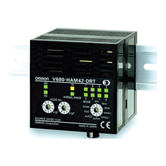
Names and Functions of Components ID Controller Part Names Operation Indicators MS: Unit status NS: Network status TR: ID Tag communications status NORM/ERR: Result of communications with ID Tag V680-HAM42-DRT OMRON Data/Error Code Indicators (Two-color) Data (green) Error code (red) NORM/ERR NODE No. MODE... - Page 21 Section 2 Names and Functions of Components Functions Operation Indicators MS Indicator (Machine Status) The MS indicator shows the Controller status. Status Definition Lit green Normal Flashing green Settings not made. Lit red Fatal error Flashing red Non-fatal error Not lit No power NS Indicator (Network Status) The NS indicator shows the network status.
- Page 22 Section 2 Names and Functions of Components Mode Switch The mode switch sets the DeviceNet Remote ID Controller’s operating mode. Mode Symbol Description 4-byte access mode 16CH 26-byte access mode 32CH 58-byte access mode SYNC1 V600-compatible Trigger Mode, 100-ms output time SYNC2 V600-compatible Trigger Mode, 500-ms output time AUTO1...
- Page 23 Section 2 Names and Functions of Components DeviceNet Connector The DeviceNet connector port connects the DeviceNet Remote ID Controller to the Master Unit. Use the enclosed connector. Enclosed connector model: FKC2.5/5-ST-5.08-RFAUM (Phoenix Contact) Pin No. Name Signal type Power supply negative side CAN_L Low communications data...
-
Page 24: Antennas
Section 2 Names and Functions of Components Antennas (2) Communications surface (3) Ferrite core (4) Connector (2) Communications (1) Operation indicator (3) Ferrite core sufrace (4) Connector (2) Communications surface (3) Ferrite core (4) Connector (1) Operation indicator (2) Communications surface (1) Operation (3) Ferrite core indicator... -
Page 25: Id Tags
Section 2 Names and Functions of Components ID Tags The ID Controller communications with the ID Tags through the Antenna to read and write data in the internal memory of the ID Tags. The printed side is the communications surface. Mount the ID Tags with the communications surfaces facing the Antenna. - Page 26 Section 2 Names and Functions of Components MEMO RFID System User's Manual...
-
Page 27: Section 3 Functions And Operation
Section 3 Functions and Operation ID Controller ID Tags RFID System User's Manual... -
Page 28: Id Controller
ID Tag. The DeviceNet Remote ID Controller reads the Tag data and outputs the results to the PLC. Master Unit ID Tag DeviceNet Remote ID V680-HAM42-DRT Antenna Palette, etc. Sensor or Switch Auto Mode When the ID Tag of a workpiece or palette is within the communications range of the Antenna, the Remote ID Controller automatically begins communications with the ID Tag and outputs the result to the PLC. - Page 29 Section 3 Functions and Operation Test Mode During system installation or maintenance, the mode switch can be set to 7 (Test Mode) to read ID Tag data when the power supply is turned ON. The communications results are display on the operation indicators and the data/error code indicators.
- Page 30 Section 3 Functions and Operation Commands Communications with the ID Tag is controlled by commands allocated to the DeviceNet Remote ID Controller signals. Using 4-byte, 26-byte, and 56-byte Access Modes The commands given in the following table can be used if the mode switch is set to 0 to 2. Command Explanation READ...
- Page 31 Section 3 Functions and Operation Options The following functions can be used with the DeviceNet Remote ID Controller by setting the control signal options. Using 4-byte, 26-byte, and 56-byte Access Modes The functions given in the following table can be used if the mode switch is set to 0 to 2. Function Explanation Communications Speed...
- Page 32 Section 3 Functions and Operation Noise Measurement You can check whether noise that affects communications with ID Tags exists in the area where the Antenna and ID Controller are installed. When a noise measurement command is sent from the PLC, the noise strength received by the Antenna is output in a value from 00 to 99.
-
Page 33: Id Tags
Section 3 Functions and Operation ID Tags ID Tag Memory Map V680-D1KP@@ Address (hex) Data 0000 0001 0002 0003 User area 03E6 03E7 1 byte V680-D2KF@@ Address (hex) Data 0000 0001 0002 0003 User area 07CEH 07CFH 1 byte V680-D8KF@@ Address (hex) Data 0000... - Page 34 Section 3 Functions and Operation Write Protection The write protection function protects important data stored in the memory of a ID Tag, such as the product model or type, from being overwritten inadvertently. Enable the write protection function after writing important data as described in this section. Setting Write Protection For the write protection function to be effective, it must be enabled or disabled in both the DeviceNet Remote ID Controller settings and the ID Tag settings.
- Page 35 Section 3 Functions and Operation Example of Write Protection Start Address Is Lower Than the End Address The memory area between the start address and end address will be write-protected. 0000 Address Upper digits Lower digits 0015 Write-protected 0000H 0120 0001H 0002H 0003H...
- Page 36 Section 3 Functions and Operation Start Address Is Higher Than End Address The memory area between the start address and the last ID Tag address, as well as the area between 0004H and the end address will be write-protected. Address Upper digits Lower digits 0000H...
-
Page 37: Section 4 Installation, Connections, And Wiring
Section 4 Installation, Connections, and Wiring DeviceNet Remote ID Controller Installing Antennas Installing ID Tags RFID System User's Manual... -
Page 38: Devicenet Remote Id Controller
Installation, Connections, and Wiring DeviceNet Remote ID Controller Installation To ensure full functionality of the V680-HAM42-DRT DeviceNet Remote ID Controller, follow the instructions provided in this section for installation. Installation Site Do not install the DeviceNet Remote ID Controller in the following locations. - Page 39 DIN Track, pull the End Plate downwards and tighten the screw. Recommended tightening torque: 1.2 N·m. Mounting Interval The V680-HAM42-DRT DeviceNet Remote ID Controllers will generate heat if they are mounted side- by-side. Leave space between the Controllers of at least 10 mm. 10 mm min.
- Page 40 If the connector is difficult to remove, press on the DeviceNet Remote ID Controller while pulling on the connector. Do not connect cables to the connector after attaching the connector to the DeviceNet Remote ID Controller. Use the recommended Power Supply (S8VS-03024, OMRON). RFID System User's Manual...
- Page 41 If the connector is difficult to remove, press on the DeviceNet Remote ID Controller while pulling on the connector. Do not connect cables to the connector after attaching the connector to the DeviceNet Remote ID Controller. Use the recommended Power Supply (S8VS-03024, OMRON). RFID System User's Manual...
- Page 42 Section 4 Installation, Connections, and Wiring Antenna Connector Mounting the Antenna Hold the connector part of the Antenna and insert it into the Antenna port while matching the key on the Unit with the groove on the connector. Antenna connector Turn the connector clockwise to lock it in place.
-
Page 43: Installing Antennas
Section 4 Installation, Connections, and Wiring Installing Antennas V680-HS51 Install the Antenna using the nuts and toothed washers that are provided on both sides of the mounting material, as shown in the diagram below. Metallic material Antenna +0.5 dia. Toothed washers Securely tighten the screws to a maximum torque of 6 N·m. - Page 44 Section 4 Installation, Connections, and Wiring V680-HS63 Installation from the Front Coil center Two, M4 ±0.2 Installation from the Back Insert the nuts that come with the Antenna into sections A. Two, M4 Coil center ±0.2 Securely tighten screws to a maximum torque of 1.2 N·m. RFID System User's Manual...
- Page 45 Section 4 Installation, Connections, and Wiring V680-HS65 Use M4 screws and spring washers (in four places) for Antenna installation. Four, M4 ±0.2 Tighten the screws to a torque of 0.7 to 1.2 N·m. There are no restrictions on the mounting direction or the direction of access to the Tag, but if the Antenna is to be installed near a device such as a conveyance belt, make sure there is no danger of the Antenna being...
-
Page 46: Installing Id Tags
Section 4 Installation, Connections, and Wiring Installing ID Tags V680-D1KP52MT Tag Installation Mount Tags as shown in the diagram on the right. The epoxy R0.2 max. adhesives listed in the following table are recommended for the given temperature ranges. +0.1 dia. - Page 47 Section 4 Installation, Connections, and Wiring V680-D1KP66MT Mount the ID Tag to metal using M3 pan-head screws Mounting Hole Dimensions from the marked side. Tighten the screws to a torque Two, M3 of 0.3 to 0.5 N·m. M3 pan-head screw ±0.2 Marked ±0.2...
- Page 48 Section 4 Installation, Connections, and Wiring V680-D2KF67/-D2KF67M Tag Installation Secure the Tag with M3 screws. Tighten the screws Mounting Hole Dimensions to a torque of 0.6 N·m or less. Two, M3 M3 pan-head screw ±0.2 Marked ±0.2 side V680-D8KF68/-D32KF68 Tag Installation Secure the Tag with M4 screws.
-
Page 49: Section 5 I/O Settings And Control Methods
Section 5 I/O Settings and Control Methods I/O Specifications Timing Charts RFID System User's Manual... -
Page 50: I/O Specifications
Section 5 I/O Settings and Control Methods I/O Specifications I/O Allocation Table Mode: 4-byte Access The DeviceNet Remote ID Controller is allocated 64 inputs (4 words) and 64 outputs (4 words) in the PLC. The inputs and outputs that are allocated (X words, Y words) depend on the node address set for the Master and the DeviceNet Remote ID Controller. - Page 51 Section 5 I/O Settings and Control Methods Signal Names and Functions Master Unit to Remote ID Controller Category Symbol Meaning Interface signal INHIBT/TRG Auto Mode: Functions as INHIBT. 0: No communications with ID Tag. 1: Communications with ID Tag. Sync Mode: Functions as TRIG. 1: Communications with ID Tag.
- Page 52 Section 5 I/O Settings and Control Methods Mode: 26-byte/58-byte Access In 26-byte Access Mode, the DeviceNet Remote ID Controller is allocated 256 inputs (16 words) and 256 outputs (16 words) in the PLC, and in 58-byte Access Mode, it is allocated 512 inputs (32 words) and 512 outputs (32 words) in the PLC.
- Page 53 Section 5 I/O Settings and Control Methods V600-compatible Mode The DeviceNet Remote ID Controller is allocated 32 inputs (2 words) and 32 outputs (2 words) in the PLC. The inputs and outputs that are allocated (X words, Y words) depend on the node address set for the Master and the DeviceNet Remote ID Controller.
- Page 54 Section 5 I/O Settings and Control Methods Signal Names and Functions Master Unit to Remote ID Controller Category Symbol Meaning Interface signal INHIBT/TRG Auto Mode: Functions as INHIBT. 0: No communications with ID Tag. 1: Communications with ID Tag. Sync Mode: Functions as TRIG. 1: Communications with ID Tag.
- Page 55 Section 5 I/O Settings and Control Methods Detailed Command Settings Using 4-byte, 26-byte, and 58-byte Access Modes DATA READ Master Unit to DeviceNet Remote ID Controller Signal Bit length Value Description CMD0 to 3 0000B Data read LEN0 to LEN7 01H to 3AH Number of bytes to process (no ASCII/hex conversion) 01H to 74H...
- Page 56 Section 5 I/O Settings and Control Methods DATA WRITE Master Unit to DeviceNet Remote ID Controller Signal Bit length Value Description CMD0 to 0001B DATAN WRITE CMD3 LEN0 to LEN7 01H to 3AH Number of bytes to process (no ASCII/hex conversion) 01H to 74H Number of bytes to process (ASCII/hex conversion) ADDR0 to...
- Page 57 Section 5 I/O Settings and Control Methods BIT SET Master Unit to DeviceNet Remote ID Controller Signal Bit length Value Description CMD0 to 0010B BIT SET CMD3 LEN0 to LEN7 1 to 4 Number of BIT SET data bytes An error will occur if 0, or 5 or higher is specified. ADDR0 to 0000H to FFFFH BIT SET start address...
- Page 58 Section 5 I/O Settings and Control Methods BIT CLEAR Master Unit to DeviceNet Remote ID Controller Signal Bit length Value Description CMD0 to 0011B BIT Clear CMD3 LEN0 to LEN7 1 to 4 Number of BIT CLEAR data bytes A specification error will occur if 0H, or 5H or higher is specified. ADDR0 to 0000H to FFFFH BIT CLEAR start address...
- Page 59 Section 5 I/O Settings and Control Methods DATA FILL Master Unit to DeviceNet Remote ID Controller Signal Bit length Value Description CMD0 to 0100B DATA FILL CMD3 LEN0 to LEN7 1H to FH Number of blocks to process (specified number of blocks x 8 bytes) 4-byte mode If the number of blocks is 0, all memory will be selected.
- Page 60 Section 5 I/O Settings and Control Methods NOISE MEASUREMENT Master Unit to DeviceNet Remote ID Controller Signal Bit length Value Description CMD0 to 0111B NOISE MEASUREMENT CMD3 DeviceNet Remote ID Controller to Master Unit Mode: 4-byte Access Signal Bit length Value Description NORM...
- Page 61 Section 5 I/O Settings and Control Methods Using V600-compatible Mode BIT SET Master Unit to DeviceNet Remote ID Controller Signal Bit length Value Description WRITE/READ Write operation WT_MODE1 BIT WRITE WT_MODE2 BIT SET WT_BYTE 0 or 1 If the bit is 0, the operation will be 8-bit write, and 16-bit write if the bit is 1.
- Page 62 Section 5 I/O Settings and Control Methods BIT CLEAR Master Unit to DeviceNet Remote ID Controller Signal Bit length Value Description WRITE/READ Write operation WT_MODE1 BIT WRITE WT_MODE2 BIT CLEAR WT_BYTE 0 or 1 If the bit is 0, the operation will be 8-bit write, and 16-bit write if the bit is 1.
-
Page 63: Timing Charts
Section 5 I/O Settings and Control Methods Timing Charts Trigger Mode The Trigger Mode timing chart is shown below. Mode Switch Settings 0 to 2 (4-byte, 26-byte, and 58-byte Access Modes) Communications Range ID Tag BUSY NORM ERR1 ERR_SUB C D E ID Tag within the Antenna's Communications Range A: The PLC turns ON TRG, and sends the execution command to DeviceNet Remote ID Controller. - Page 64 Section 5 I/O Settings and Control Methods Mode Switch Settings 3 and 4 (V600-compatible Trigger Mode) Communications Range ID Tag BUSY Set time NORM Set time ERR1 ERR_SUB C D E ID Tag within the Antenna's Communications Range A: The PLC turns ON TRG, and sends the execution command to DeviceNet Remote ID Controller. B: The DeviceNet Remote ID Controller receives TRG, determines the CMD (command), LEN (data length), and ADDR (start address), then turns ON HS output, starts communications with the ID Tag, and turns ON BUSY.
- Page 65 Section 5 I/O Settings and Control Methods Auto Mode with 100-ms Output Time The timing chart for Auto Mode with a 100-ms output time is shown in the following figure. Mode Switch Settings 0 to 2 (4-byte, 26-byte, and 58-byte Access Mode) Communications Communications Range ID Tag...
- Page 66 Section 5 I/O Settings and Control Methods Mode Switch Setting 5 (V600-compatible Auto Mode) ID Tag Communications Communications Range Range INHIBIT BUSY 100 ms NORM ERR_SUB A B C A: The PLC turns ON INHIBIT and sends the execution command to the DeviceNet Remote ID Controller.
- Page 67 Section 5 I/O Settings and Control Methods Auto Mode (500 ms Output Time) The timing chart for Auto Mode with a 500-ms output time is shown in the following figure. Mode Switch Settings 0 to 2 (4-byte, 26-byte, and 58-byte Access Mode) Communications Communications ID Tag...
- Page 68 Section 5 I/O Settings and Control Methods Mode Switch Setting 6 (V600-compatible Auto Mode) Communications Communications Range ID Tag Range INHIBIT BUSY 500 ms NORM ERR_SUB A B C A: The PLC turns ON INHIBIT, and sends the execution command to the DeviceNet Remote ID Controller.
- Page 69 Section 5 I/O Settings and Control Methods Noise Check Control Handling Errors Check the status of the DeviceNet Remote ID Controller network and hardware by using the MS and NS operation indicators. MS Indicator (Machine Status) Error Corrective action Lit red Hardware error If the error continues after resetting the power, replace the DeviceNet Remote ID Controller.
- Page 70 Section 5 I/O Settings and Control Methods Indicator Output bits Error Corrective action Bit 7 to bit 0 Error Mode switch setting error Set the mode switch correctly. Flashing red Termination + Switch Error Bit 7 to bit 0 Error The DeviceNet Remote If the error continues after resetting the power, replace the Lit red...
-
Page 71: Section 6 Appendices
Section 6 Appendices Product Specifications Dimensions Characteristics Reference Data Chemical Resistance of the Antennas Chemical Resistance of Tags Degree of Protection RFID System User's Manual... -
Page 72: Product Specifications
Section 6 Appendices Product Specifications DeviceNet Remote ID Controller General Specifications V680-HAM42-DRT Item Model V680-HAM91/V680-HAM81 Supply volTage 24 VDC +10%/-15%, Ripple (p-p): 10% max. Power consumption 3.6 W (5 W max.) −10 to 55°C (with no icing) Ambient operating temperature −20 to 65°C (with no icing) - Page 73 Section 6 Appendices Antenna Four models of Antennas can be used with I/O Sensors. Select the best Antenna for the application. General Specifications V680-HS51 Item Model V680-HS51 −10 to 60°C (with no icing) Ambient operating temperature −25 to 75°C (with no icing) Ambient storage temperature Ambient operating...
- Page 74 Section 6 Appendices V680-HS63-W/-R Item Model V680-HS63-W V680-HS63-R (Standard cable, waterproof connector) (Flexible cable, non-waterproof connector) −10 to 60°C (with no icing) Ambient operating temperature −25 to 75°C (with no icing) Ambient storage temperature Ambient operating 35% to 95% (with no condensation) humidity Insulation resistance 20 MΩ...
- Page 75 Weight Approx. 0.5 g Metal countermeasures Note: OMRON Test Method Usage condition: 10 m or less under water in natural conditions 1. No water ingress after 1 hour under water at 2 atmospheres of pressure. 2. Sensing distance and insulation resistance specifications must be met after 100 repetitions of half hour in 5°C water and half hour in 85°C water.
- Page 76 Approx. 7.5 g Metal countermeasures None Note: OMRON Test Method Usage condition: 10 m or less under water in natural conditions 1. No water ingress after 1 hour under water at 2 atmospheres of pressure. 2. Sensing distance and insulation resistance specifications must be met after 100 repetitions of half hour in 5°C water and half hour in 85°C water.
- Page 77 Section 6 Appendices V680-D1KP66T-SP Item Specifications Memory capacity 1,000 bytes Memory type EEPROM Data backup time 10 years after writing (85°C or less) Memory longevity 100,000 times per block (25°C) When communicating: −25 to 70°C (with no icing) Ambient operating When not communicating: −40 to 110°C (with no icing) temperature Ambient operating...
- Page 78 Section 6 Appendices V680-D2KF67/-D2KF67M Item Model V680-D2KF67 V680-D2KF67M Memory capacity 2,000 bytes (user area) Memory type FRAM Data backup time 10 years after writing (55°C or less), 2.9 years after writing (85°C max.) Memory longevity 10 billion times per block. Access frequency (See note.): 10 billion times −25 to 85°C (with no icing) Ambient operating temperature...
- Page 79 Section 6 Appendices V680-D8KF68/-D32KF68 Item Model V680-D8KF68 V680-D32KF68 Memory capacity 8,192 bytes (user area) 32,744 bytes (user area) Memory type FRAM Data backup time 10 years after writing (70°C max.), 6 years after writing (85°C max.) Memory longevity 10 billion times per block (85°C or less) Access frequency (See note.): 10 billion times −20 to 85°C (with no icing) Ambient operating...
-
Page 80: Dimensions
Section 6 Appendices Dimensions DeviceNet Remote ID Controller V680-HAM42-DRT Data indicator Operation indicator Node address switches Mode switch Antenna connector port 21.5 20.5 5.06 DeviceNet connector Power supply terminals (Unit: mm) RFID System User's Manual... - Page 81 Section 6 Appendices Antennas V680-HS51 (Unit: mm) Two toothed washers Connector Ferrite core Two lock nuts Mounting Hole Dimensions M12 x 1 Coaxial cable, 2.9 dia., standard length: 2 m Insulation cover Case material Brass Communications surface ABS resin Fill resin Epoxy resin Cable PVC (gray)
- Page 82 Section 6 Appendices V680-HS52 V680-HS52-W (Unit: mm) 22.5 dia. Two toothed washers Two lock nuts M22 × 1 Mounting Hole Dimensions Ferrite core Operation indicator Antenna Connector 35 dia. 47.8 Insulation cover Coaxial cable, 5.5 dia., standard length: 2 m Case material Brass Communications surface...
- Page 83 Section 6 Appendices V680-HS63-R/-W V680-HS63-W (Unit: mm) Antenna Ferrite core Connector Insulation cover Coaxial cable, 5.5 dia., Operation indicator standard length: 2 m Note: Mounting Hole Dimensions Two, M4 or 4.5 dia. holes Coil center Case material ABS resin Fill resin Epoxy resin Cable PVC (gray)
- Page 84 Section 6 Appendices V680-HS65-R/-W V680-HS65-W (Unit: mm) 90±0.2 Four, 4.5 dia. (Mounting holes) Ferrite core Connector Operation indicator Bushing Insulation cover Coaxial cable, 5.5 dia., standard length: 2 m Case material ABS resin Fill resin Epoxy resin Cable PVC (gray) V680-HS65-R (Unit: mm) 90±0.2...
- Page 85 Section 6 Appendices ID Tags V680-D1KP52MT R0.2 dia. −0.1 −0.1 (Unit: mm) Case material ABS resin Fill resin Epoxy resin When embedding the V680-D1KP52MT into a metal surface, use the V680-HS52 Antenna. Transmission will not be possible if the V680-HS63 Antenna is used. The side with the markings is the communications surface.
- Page 86 Section 6 Appendices Tag Heat Resistivity • Storing Tags under high temperatures will adversely affect the performance of the internal parts and the service life of the Tags. • An LTPD of 10% was determined during the evaluation for Tags that reached the end of their life after testing under the following test conditions.
- Page 87 Section 6 Appendices V680-D2KF52M (Unit: mm) R0.2 dia. −0.1 −0.1 Case material PPS resin Fill resin Epoxy resin When embedding the V680-D1KP52M into a metal surface, use the V680-HS51/-HS52 Antenna. Transmission will not be possible if the V680-HS63 Antenna is used. The side with the markings is the communications surface.
- Page 88 Section 6 Appendices V680-D8KF68/-D32KF68 Two, 4.5-dia. (Unit: mm) mounting holes Mounting Hole Dimensions 44±0.2 Two, M4 44±0.2 Case material PBT resin Fill resin Epoxy resin The side with the markings is the communications surface. Mount the Tag with this side facing the Antenna. V680-A81 Attachment Two, 4.5-dia.
-
Page 89: Characteristics
Section 6 Appendices Characteristics Communications Distance Specifications V680-D1KP52MT Antenna ID Tag Communications distance 0.5 to 6.5 mm (Axis offset: ±2) Read V680-D1KP52MT 0.5 to 6.0 mm (Axis offset: ±2) Write V680-HS51 0.5 to 3.5 mm (Axis offset: ±2) Read V680-D1KP52MT embedded in metal (steel) 0.5 to 3.0 mm (Axis offset: ±2) Write... - Page 90 Section 6 Appendices V680-D1KP66T Antenna ID Tag Communications distance 1.0 to 17.0 mm (Axis offset: ±2) Read V680-HS52 V680-D1KP66T 1.0 to 17.0 mm (Axis offset: ±2) Write 5.0 to 30.0 mm (Axis offset: ±10) Read V680-HS63 V680-D1KP66T 5.0 to 25.0 mm (Axis offset: ±10) Write 5.0 to 47.0 mm (Axis offset: ±10) Read...
- Page 91 Section 6 Appendices V680-D1KP66MT Antenna ID Tag Communications distance 1.0 to 16.0 mm (Axis offset: ±2) Read V680-D1KP66MT V680-HS52 embedded in metal (steel) 1.0 to 14.0 mm (Axis offset: ±2) Write 5.0 to 25.0 mm (Axis offset: ±10) Read V680-D1KP66MT V680-HS63 5.0 to 20.0 mm Axis offset: ±10) embedded in metal (steel)
- Page 92 Section 6 Appendices V680-D1KP66-SP Antenna ID Tag Communications distance 0 to 15.0 mm (Axis offset: ±2) Read V680-HS52 0 to 15.0 mm (Axis offset: ±2) Write 0 to 25.0 mm (Axis offset: ±10) Read V680-HA63A V680-HS63 0 to 20.0 mm (Axis offset: ±10) Write 0 to 42.0 mm (Axis offset: ±10) Read...
- Page 93 Section 6 Appendices V680-D2KF52M Antenna ID Tag Communications distance 0.5 to 5.5 mm (Axis offset: ±2) Read V680-D2KF52M 0.5 to 5.5 mm (Axis offset: ±2) Write V680-HS51 0.5 to 3.5 mm (Axis offset: ±2) Read V680-D2KF52M 0.5 to 3.5 mm (Axis offset: ±2) embedded in metal (steel) Write 0.5 to 8.0 mm (Axis offset: ±2)
- Page 94 Section 6 Appendices V680-D2KF67 Antenna ID Tag Communications distance 7.0 to 30.0 mm (Axis offset: ±2) Read V680-HS52 V680-D2KF67 7.0 to 30.0 mm (Axis offset: ±2) Write 7.0 to 30.0 mm (Axis offset: ±10) Read V680-HS63 V680-D2KF67 7.0 to 30.0 mm (Axis offset: ±10) Write 5.0 to 42.0 mm (Axis offset: ±10) Read...
- Page 95 Section 6 Appendices V680-D2KF67M Antenna ID Tag Communications distance 6.0 to 25.0 mm (Axis offset: ±2) Read V680-D2KF67M V680-HS52 embedded in metal (steel) 6.0 to 25.0 mm (Axis offset: ±2) Write 6.0 to 25.0 mm (Axis offset: ±10) Read V680-D2KF67M V680-HS63 6.0 to 25.0 mm (Axis offset: ±10) embedded in metal (steel)
- Page 96 Section 6 Appendices V680-D8KF68/-D32KF68 Antenna ID Tag Communications distance 5.0 to 45.0 mm (Axis offset: ±2) Read V680-D8KF68 5.0 to 45.0 mm (Axis offset: ±2) Write 5.0 to 35.0 mm (Axis offset: ±10) Read V680-D8KF68 (with ATTACHMENT, V680-A81) with metal on back surface (steel) 5.0 to 35.0 mm (Axis offset: ±10) Write V680-HS63...
- Page 97 Section 6 Appendices Communications Area 680-D1KP52MT ● V680-HS51 and V680-D1KP52MT ● V680-HS51 and V680-D1KP52MT (Embedded in Metal: Steel) Read Read Write Write 0 −15 −10 −5 0 −15 −10 −5 X Axis (Unit: mm) X Axis (Unit: mm) ● V680-HS52 and V680-D1KP52MT ●...
- Page 98 Section 6 Appendices V680-D1KP66T ● V680-HS52 and V680-D1KP66T ● V680-HS63 and V680-D1KP66T Read Read Write Write −50 −40 −30 −20 −10 −50 −40 −30 −20 −10 X Axis X Axis (Unit: mm) (Unit: mm) ● V680-HS65 and V680-D1KP66T Read Write −100 −80 −60...
- Page 99 Section 6 Appendices V680-D1KP66T-SP ● V680-HS52 and V680-D1KP66T-SP ● V680-HS63 and V680-D1KP66T-SP Read Read Write Write −50 −40 −30 −20 −10 −50 −40 −30 −20 −10 X Axis (Unit: mm) X Axis (Unit: mm) ● V680-HS65 and V680-D1KP66T-SP Read Write −100 −80 −60...
- Page 100 Section 6 Appendices V680-D2KF52M ● V680-HS51 and V680-D2KF52M ● V680-HS51 and V680-D2KF52M (Embedded in Metal: Steel) Read/Write Read/Write 0 −15 0 −15 −10 −5 −10 −5 X Axis (Unit: mm) X Axis (Unit: mm) ● V680-HS52 and V680-D2KP52M ● V680-HS52 and V680-D2KF52M (Embedded in Metal: Steel) Read/Write Read/Write...
- Page 101 Section 6 Appendices V680-D2KF67 ● V680-HS52 and V680-D2KF67 ● V680-HS63 and V680-D2KF67 Read/Write Read/Write −60 −40 −20 −60 −40 −20 X Axis (Unit: mm) X Axis (Unit: mm) ● V680-HS65 and V680-D2KF67 Read/Write −100 −80 −60 −40 −20 X Axis (Unit: mm) V680-D2KF67M ●...
- Page 102 Section 6 Appendices V680-D8KF68/-D32KF68 ● V680-HS63 and V680-D8KF68/-D32KF68 ● V680-HS63 and V680-D8KF68/-D32KF68 (Horizontal-facing ID Tag) (Vertical-facing ID Tag) Read/Write Read/Write −80 −60 −40 −20 −80 −60 −40 −20 X Axis X Axis (Unit: mm) (Unit: mm) ● V680-HS63 and V680-D8KF68/-D32KF68 ●...
- Page 103 Section 6 Appendices Communications Time The communications time is the time required for communications between the Antenna and the ID Tag. The communications time of the DeviceNet Remote ID Controller is longer when data is being written. Communications Time Specifications Model V680-HAM91/V680-HAM81 Read...
-
Page 104: Reference Data
Section 6 Appendices Reference Data Effect of Surrounding Metals on the Antenna (Reference) V680-HS51 When embedding the Antenna in metal, be sure the metal does not extend beyond the communications section (coil surface) of the Antenna. Surrounding metal Surrounding metal (steel) (steel) R18 min. - Page 105 Section 6 Appendices V680-HS63 In addition to surface mounting, it is also possible to embed the V680-HS63 in a metal casing to protect it from being struck by other objects. To prevent malfunctioning, allow a space of at least 30 mm between the Antenna and the sides of the metal casing.
- Page 106 Section 6 Appendices Effect of Surrounding Metals on the ID Tags V680-D1KP52MT Differences in Surrounding Metals Communications distances are affected by the type of metal in back of or surrounding the Tag, as shown in the following table. Steel Brass Aluminum V680-D2KF52M 100%...
- Page 107 Section 6 Appendices V680-D2KF52M Differences in Surrounding Metals Communications distances are affected by the type of metal in back of or surrounding the Tag, as shown in the following table. Steel Brass Aluminum V680-D2KF52M 100% 80% to 85% 80% to 85% 75% to 80% Note: The value for steel around or behind the Tag is set to 100%.
- Page 108 Section 6 Appendices V680-D8KF67/-D32KF68 Effect of Surrounding Metals (Reference) •Special Attachment (V680-A81) Installation Direction M4 screw Spring washer The transmission distance will be reduced if there is metal in back of Flat washer a Tag. When mounting on a metal surface, use the special Attachment (V680-A81) of another sales or insert a non-metallic spacer (e.g., plastic, wood, etc.).
- Page 109 Section 6 Appendices Effect of Metal behind Tags (Reference) V680-D1KP66T Effect of Metal behind Tags (Reference) The V680-D1KP66T communications distance is reduced if there is any metal material behind the Tag. If the Tag is to be mounted to metal, then either use a V600-A86 Attachment (sold separately) or insert a non-metal spacer (such as plastic or resin).
- Page 110 Section 6 Appendices V680-D1KP66T-SP The V680-D1KP66T-SP communications distance is reduced if there is any metal material behind the Tag. If the Tag is mounted on metal, insert a non-metal spacer (such as plastic or resin). The relationship between the distance from the Tag to the metal surface and the communications distance is shown below.
- Page 111 Section 6 Appendices V680-D2KF67 Effect of Metal behind Tags (Reference) The V680-D2KF67 communications distance is reduced if there is any metal material behind the Tag. ● V680-HS52 and V680-D2KF67 ● V680-HS63 and V680-D2KF67 (mm) (mm) Distance to metal (x) Distance to metal (x) ID Tag ID Tag Antenna...
- Page 112 Section 6 Appendices Mutual Interference between Antennas (Reference) To prevent malfunctioning due to mutual interference when using more than one Antenna, leave sufficient space between them as shown in the following diagrams. V680-HS51 • Installing the Antennas Facing Each Other •...
- Page 113 Section 6 Appendices Mutual Interference with ID Tags (Reference) To prevent malfunctioning due to mutual interference when using more than one Tag, leave sufficient space between them as shown in the following diagram. V680-D1KP52MT 25 mm min. 25 mm min. V680-D1KP66T 100 mm min.
- Page 114 Section 6 Appendices V680-D2KF52M When V680-HS51, V680-HS52, and V680-HS63 Are Used 25 mm min. 25 mm min. V680-D2KF67 When V680-HS52, V680-HS63, and V680-HS65 Are Used 200 mm min. 200 mm min. V680-D2KF67M When V680-HS52, V680-HS63, and V680-HS65 Are Used 120 mm min. 120 mm min.
- Page 115 Section 6 Appendices V680-D8KF68/-D32KF68 When V680-HS63 Is Used 120 mm min. 120 mm min. 120 mm min. 120 mm min. When V680-HS65 Is Used 150 mm min. 150 mm min. 150 mm min. 150 mm min. RFID System User's Manual...
- Page 116 Section 6 Appendices Influence of Tag Angle (Reference) Install Antennas and Tags as close to parallel to each other as possible. Communications are possible even when an Antenna and a Tag are mounted at an angle, but the communications distance will be shortened. The relation between the angle and the communications distance is shown below.
- Page 117 Section 6 Appendices Reduction in Communications Distance for V680-D1KP66T Angle Tag angle (θ°) V680-HS52 and V680-D1KP66T −1% −2% −4% −7% V680-HS63 and V680-D1KP66T −2% −3% −5% −9% V680-HS65 and V680-D1KP66T −1% −3% −6% −11% Measurement Conditions V680-HS52 and V680-D1KP66T V680-HS63 and V680-D1KP66T θ...
- Page 118 Section 6 Appendices Reduction in Communications Distance for V680-D1KP66MT Angle Tag angle (θ°) V680-HS52 and V680-D1KP66MT −1% −2% −5% −9% (Metal on back: Steel) V680-HS63 and V680-D1KP66MT −1% −4% −7% −13% (Metal on back: Steel) V680-HS65 and V680-D1KP66MT −1% −6% −15% (Metal on back: Steel) ---: Measurement is not possible because Antenna and Tag would strike each other.
- Page 119 Section 6 Appendices Reduction in Communications Distance for V680-D1KP66T-SP Angle Tag angle (θ°) V680-HS52 and V680-D1KP66T −1% −2% −4% −7% V680-HS63 and V680-D1KP66T −2% −3% −5% −9% V680-HS65 and V680-D1KP66T −1% −3% −6% −11% Measurement Conditions V680-HS52 and V680-D1KP66T V680-HS63 and V680-D1KP66T θ...
- Page 120 Section 6 Appendices Reduction in Communications Distance for V680-D2KF52M Angle Tag angle (θ°) V680-HS51 and V680-D2KF52M −2% −6% −22% -− V680-HS51 and V680-D2KF52M −7% −30% (Metal on back: Steel) V680-HS52 and V680-D2KF52M −2% −5% V680-HS52 and V680-D2KF52M −2% −7% (Metal on back: Steel) V680-HS63 and V680-D2KF52M −1% −4%...
- Page 121 Section 6 Appendices Reduction in Communications Distance for V680-D2KF67 Angle Tag angle (θ°) V680-HS52 and V680-D2KF67 −1% −2% V680-HS63 and V680-D2KF67 −1% −2% −3% −6% V680-HS65 and V680-D2KF67 −1% −3% −7% −11% Measurement Conditions V680-HS52 and V680-D2KF67 V680-HS63 and V680-D2KF67 θ...
- Page 122 Section 6 Appendices Reduction in Communications Distance for V680-D2KF67M Angle Tag angle (θ°) V680-HS52 and V680-D2KF67M −1% −2% −4% −6% (Metal on back: Steel) V680-HS63 and V680-D2KF67M −2% −5% −8% −14% (Metal on back: Steel) V680-HS65 and V680-D2KF67M −2% −7% −16% −31% (Metal on back: Steel)
- Page 123 Section 6 Appendices Reduction in Communications Distance for V680-D8KF68/-D32KF68 Angle Tag angle (θ°) V680-HS63 and V680-D8KF68/-D32KF68 (Horizontal-facing ID Tag) V680-HS63 and V680-D8KF68/-D32KF68 −1% −2% −3% −5% (Vertical-facing ID Tag) V680-HS65 and V680-D8KF68/-D32KF68 −1% −2% −4% −6% (Horizontal-facing ID Tag) V680-HS65 and V680-D8KF68/-D32KF68 −1% −3% −6%...
- Page 124 Masters, installing the EDS file in the Configurator also enables setting specific parameters for each Slave by using the Configurator. If the EDS file cannot be obtained or the non-OMRON Configurator does not support EDS files, you must directly input the connection type and the data size.
- Page 125 Section 6 Appendices Object Implementation Identity Object (0 × 01) Object class Attribute Not supported Service Not supported Object instance Attribute Description Value (hex) ✕ Vender ✕ Product type ✕ Product code ✕ Revision ✕ Status (Bits Supported) bit 0 only ✕...
- Page 126 Section 6 Appendices Object instance Attribute Description Value (hex) ✕ MAC ID ✕ Baud rate ✕ ✕ Bus off counter ✕ Allocation information ✕ MAC ID switch changed ✕ ✕ Baud rate switch changed ✕ MAC ID switch value ✕ ✕...
- Page 127 Section 6 Appendices Object instance1 Section Data Maximum number of instances Instance type Explicit Message Production trigger Cyclic Transport type Server Transport class Attribute Description Value (hex) ✕ State ✕ Instance type ✕ Transport class trigger ✕ Produced connection ID ✕...
- Page 128 Section 6 Appendices Object instance2 Section Data Maximum number of instances Instance type Polled I/O Production trigger Cyclic Transport type Server Transport class Attribute Description Value (hex) ✕ State ✕ Instance type ✕ Transport class trigger ✕ Produced connection ID ✕...
- Page 129 Section 6 Appendices Object instance3 Section Data Maximum number of instances Instance type Polled I/O Production trigger Cyclic Transport type Server Transport class Attribute Description Value (hex) ✕ State ✕ Instance type ✕ Transport class trigger ✕ Produced connection ID ✕...
-
Page 130: Chemical Resistance Of The Antennas
Section 6 Appendices Chemical Resistance of the Antennas Applicable Models V680-HS51 V680-HS52-W/R V680-HS63-W/R V680-HS65-W/R ABS resin is used for case material and epoxy resin for filling material. Refer to the following lists and do not use chemicals that affect ABS and epoxy resin. Chemicals That Cause Deformations, Cracks, Etc. -
Page 131: Chemical Resistance Of Tags
Section 6 Appendices Chemical Resistance of Tags Applicable Models V680-D1KP52 V680-D2KF52M PPS resin is used for case material and epoxy resin for filling material. Refer to the following lists and do not use chemicals that affect PPS and epoxy resin. Tags cannot be used in applications with explosion-proof specifications. - Page 132 Section 6 Appendices Applicable Models V680-D1KP66T/MT At room At room Chemical temper- 90°C Chemical temper- 90°C ature ature Hydrochloric acid Sodium hypochlorite Phenol solution Sulfuric acid Glacial acetic acid Acetic acid Oleic acid Methyl alcohol Nitric acid Ethyl alcohol Ethyl acetate Sebacic acid diethylhexyl Hydrogen fluoride solution Acetone...
- Page 133 Section 6 Appendices Applicable Model V680-D1KP66T-SP PFA is used for the V680-D1KP66T-SP ID Tag coating. Refer to the following materials and check the characteristics before using them. Chemical Resistance of PFA Fluororesin (Reference Material) PFA: Tetrafluorethylene-Perfluoroalkylvinyletheir copolymer PFA fluororesin is non-reactive to most chemicals. It reacts to alkaline metals in the melted state, F2 (fluorine) under high temperature and high pressure, and some halogen derivatives.
- Page 134 Section 6 Appendices Organic Chemicals Residual characteristic (%) Test temperature Chemical Weight gain (%) (°C) Tensile strength Stretch Water-acetic acid Acetic anhydride Trichloroacetic acid Isooctane Naphtha Mineral oil Toluene o-Creosol Nitrobenzene Benzyl alcohol Aniline n-Butylamine Ethylenediamine Tetrahydrofuran Benzaldehyde Cyclohexane Methyl ethyl ketone Acetophenone Dimethylphtalate n-Butyl acetate...
- Page 135 Section 6 Appendices Substances Extracted from Tag (Reference) If chemicals penetrate through PFA into the Tag (V680-D1KP66T) built into the V680-D1KP66T-SP, ions may be extracted from the Tag. Results of Ion-exchange Chromatography A built-in Tag was soaked in hot water (100°C for 16 hours), and extracted ions were analyzed. The results are shown below.
- Page 136 Section 6 Appendices Applicable Models V680-D2KF67/67M Chemicals that affect Tags are shown below. ABS resin is used for case material and epoxy resin for filling material. Refer to the following lists and do not use chemicals that affect ABS and epoxy resin. Tags cannot be used in applications with explosion-proof specifications.
- Page 137 Section 6 Appendices Applicable Models V680-D8KF68/D32KF68 Chemicals that affect Tags are shown below. Polybutylene terephthalate (PBT) resin is used for case material and epoxy resin for filling material. Refer to the following lists and do not use chemicals that affect PBT and epoxy resins. Tags cannot be used in applications with explosion-proof specifications.
-
Page 138: Degree Of Protection
Section 6 Appendices Degree of Protection Ingress protection degrees (IP-@@) are determined by the following tests. Be sure to check the sealing capability under the actual operating environment and conditions before actual use. IEC (International Electrotechnical Commission) IEC 60529:1989-11 (A) First Digit: Degree of Protection from Solid Materials Degree Protection No protection... - Page 139 No adverse affect from oil drops or oil spray approaching from any direction. Oil-proof Protects against penetration of oil drops or oil spray approaching from any direction. Note: This OMRON in-house standard confirms resistance to cutting and other oils. It is equivalent to the former JEM standard. RFID System User's Manual...
- Page 140 Section 6 Appendices MEMO RFID System User's Manual...
- Page 141 Section 6 Appendices RFID System User's Manual...
-
Page 142: Revision History
Revision History A manual revision code appears as a suffix to the catalog number at the bottom of the front and rear pages. Cat. No.: NTLP-E1-01 Revision code Revision code Date Revised contents January 2008 Original production RFID System User's Manual... - Page 143 OMRON ELECTRONICS LLC One Commerce Drive Schaumburg, IL 60173-5302 U.S.A. Tel: (1) 847-843-7900/Fax: (1) 847-843-7787 OMRON ASIA PACIFIC PTE. LTD. No. 438A Alexandra Road # 05-05/08 (Lobby 2), Alexandra Technopark, Singapore 119967 Tel: (65) 6835-3011/Fax: (65) 6835-2711 OMRON (CHINA) CO., LTD.
Need help?
Do you have a question about the V680-HAM42-DRT and is the answer not in the manual?
Questions and answers