
Related Manuals for Mira elite 2


Summary of Contents for Mira elite 2
- Page 1 PUMPED ELECTRIC SHOWER Installation, Operation & Maintenance Guide THESE INSTRUCTIONS ARE TO BE LEFT WITH THE USER...
-
Page 2: Table Of Contents
Contents Section Page 1 ..Introduction ..............3 2 ..Important Safety Information .......... 4 3 ..Pack Contents Checklist ..........7 4 ..Dimensions ..............8 5 ..Wiring Diagram ..............9 6 ..Specifications ..............10 7 ..Installation Requirements ..........11 8 .. -
Page 3: Introduction
The Mira Elite 2 features an internal pump unit which has been designed to provide all year round performance, even at the highest flow rates which are necessary during the summer months. -
Page 4: Important Safety Information
1.3. DO NOT twist the individual cable cores of the live and neutral conductors, as this will prevent them from entering the terminal block. 1.4. DO NOT connect the Elite 2 to a mains-fed water supply. Such a connection will damage the appliance, and is not covered under the manufacturer’s guarantee. - Page 5 2.2. Pass on this guide in the event of change of ownership of the installation site. 2.3. Follow all warnings, cautions and instructions contained in this guide, and on or inside the Mira Sport. 2.4. The electrical installation must comply with the “Requirements for Electrical Installations”...
- Page 6 2.6.1. Institute of Plumbing (IOP), throughout the UK. 2.6.2. National Association of Plumbing, Heating and Mechanical Services Contractors (NAPH & MSC), England and Wales. 2.6.3. Scottish and Northern Ireland Plumbing Employers’ Federation (SNIPEF), Scotland and Northern Ireland. 2.7. Anyone who may have difficulty understanding or operating the controls of any shower should be attended whilst showering.
-
Page 7: Pack Contents Checklist
3 x Rubber Feet 1 x Olive 1 x Compression Nut 3 x Fixing Screws 3 x Wall Plug 1 x Mira Elite 2 2. Documentation 1 x Installation, Operation and Maintenance Guide 1 x Installer Product Checklist 1 x Customer Support Brochure... -
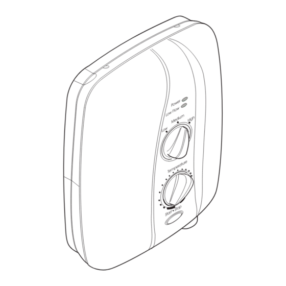
Page 8: Dimensions
Section Dimensions 270 mm 85 mm Power Low Flow Medium High 344 mm Temperature Start Stop... -
Page 9: Wiring Diagram
Section Wiring Diagram Pressure/Power Selector Switch High Load Medium Low Flow Neon Thermal Trip Motor Thermal Cutout Dual Disc Tank Connection Inlet Connector On/Off Power On Neon Solenoid Valve... -
Page 10: Specifications
2.5. The motor will absorb approximately 100 Watts maximum power under normal working conditions. 3. Standards and Approvals 3.1. The Mira Elite 2 has been designed to comply with the requirements of the British Electrotechnical Approvals Board (BEAB) and the requirements of UK Water Regulations/Bylaws (Scotland). -
Page 11: Installation Requirements
(80 millimetres head) to 1 bar (10 metres head) (i.e. the vertical distance from the base of the cold cistern to the top of the Elite 2). However, the minimum head required will increase with pipe length and the guide given in paragraph 1.17. - Page 12 DO NOT block the air ventilation gaps around the sides of the unit, either by tiling up to the sides of the unit or by using a sealant around the case. This Elite 2 is designed to be ventilated. Failure to do this may cause product failure.
- Page 13 1.17. Long pipe runs and excessive use of 90° elbows will significantly reduce the available head to supply the Elite 2. The pipework table should be completed to ensure that adequate head is available for any given application.
- Page 14 The dimension (x) is calculated from the table below to give you a minimum effective head of 80 mm which is necessary to produce a satisfactory shower in all conditions. Pipework Quantity Size Head Loss (mm) 15 mm Pipe + (B) x 120 22 mm Pipe + (B)
- Page 15 2.2. In a domestic installation, the electricity company fuse must be a minimum of 80 Amps. As the Elite 2 is a high power unit it is essential to contact your electricity supply company to ensure that the supply is adequate for the purpose.
- Page 16 Ensure the water supply is turned on as the unit must not be operated dry. 2.9. The Elite 2 is fitted with a pump motor, and some mechanical noise can be expected in addition to the noise generated by the spray from the handset.
-
Page 17: Installation
1.6. Swivel the inlet connector assembly to suit. Remove the inlet blanking cap. Avoid trapping the green earth bonding wire. 1.7. A case insert is supplied with the Mira Elite 2, this can be removed to suit the supplies entering the product. Before fitting the unit, if necessary, make sure that the case insert is fitted. - Page 18 1.10. Drill and plug the top two fixing holes. Secure the Mira Elite 2 to the wall with the screws provided. Drill the bottom fixing hole with the product in place.
- Page 19 Important! Do not fit the Mira Elite 2 to the wall and tile up to the case. The Mira Elite 2 must be fitted on to a finished flat and even wall surface (small pillars moulded on to the back of the case allow air circulation).
-
Page 20: Commissioning
Section Commissioning 1. Mira Elite 2 If you are unsure how electric showers work, please read through the Operation Section before continuing. 1.1. Make sure that the START/STOP button is in the outermost position and that the electrical supply has been isolated. - Page 21 Isolate the power at the double pole switch. Note! A slight hissing sound may be heard from the Mira Elite 2 during operation. High shower temperatures will effect the tone. This is quite normal in use.
-
Page 22: Operation
The switch will cycle on/off/on if the flow rate is not increased, and the shower temperature reduced. The “OVERHEAT” light on the Elite 2 will provide a visual indication of this condition. 1.7. When the shower is first turned on or a different temperature is selected, there will be a slight delay before the shower temperature changes, to allow the previously heated water to be used up. - Page 23 THE SPRAY PLATE HOLES MUST BE KEPT CLEAR. The spray plate should be regularly removed and cleaned in descalent. Lack of regular spray plate cleaning will lead to poor performance and cause early failure of the Mira Elite 2. 2.1. Switch on pullcord or wall mounted switch. The 'POWER' neon will provide a visual indication that the switch is on.
- Page 24 Clockwise rotation will give warmer water with less flow. Anticlockwise rotation will give cooler water with more flow. 2.6. TO TURN OFF the Mira Elite 2 press the STOP button.The shower will continue to flow for a few seconds before stopping.
- Page 25 High Medium COLD Power Low Flow Medium High Temperature Start Stop Stop Start Press to Start/Stop Hotter Cooler Operation of the Mira Elite 2...
-
Page 26: Fault Diagnosis
Fault Diagnosis Fault Diagnosis Warning! There are no user serviceable components beneath the cover of the Elite 2. Only a competent tradesperson should remove the cover. The trouble shooting information tabled below gives details on what you can do as a user without removing the cover, should you encounter difficulties whilst operating the shower. - Page 27 Shower cycles from Turn the temperature knob positioned at an unsafe hot to cold. sufficiently anti clock-wise to level causing the Elite 2 increase water flow and thermal trip to operate reduce temperature. and cut the power to the heater tank.
-
Page 28: Maintenance
Before replacing any parts ensure that the underlying cause of the malfunction has been resolved. WARNING! There are no user serviceable components beneath the cover of the Elite 2. Only a competent tradesperson should remove the cover. - Page 29 3.6. Carefully pull the flow valve and switch assembly and the heater tank away from the case. Make sure that you ease the flow valve and switch assembly off the motor/pump assembly.. 3.7. Remove the outlet connector from the heater tank. 3.8.
- Page 30 Cistern Fed Cold Water Supply Pipe PCB Assembly Motor/Pump Assembly Heater Tank Splash Guard Microswitch Electrical Supply Cable Switch Assembly Terminal Block Flow Valve Inlet Connector Assembly Heater Tank Retaining Screws Clamp Bracket Outlet Connector Clamp Bracket Flow Valve and Retaining Screws Switch Assembly Retaining Screw...
- Page 31 4. Heater Tank - Removal and Installation WARNING! Isolate the electrical and water supplies before removing the cover. Mains electricity connections are exposed when the cover is removed. 4.1. Unscrew the four cover retaining screws sufficient to remove the cover and service tunnel.
- Page 32 Cistern Fed Cold Water Supply Pipe PCB Assembly Motor/Pump Assembly Heater Tank Splash Guard Microswitch Electrical Supply Cable Switch Assembly Terminal Block Flow Valve Inlet Connector Assembly Heater Tank Retaining Screws Clamp Bracket Outlet Connector Clamp Bracket Flow Valve and Retaining Screws Switch Assembly Retaining Screw...
- Page 33 5. Motor/Pump Assembly - Removal and Installation WARNING! Isolate the electrical and water supplies before removing the cover. Mains electricity connections are exposed when the cover is removed. 5.1. Unscrew the four cover retaining screws sufficient to remove the cover and service tunnel.
- Page 34 Cistern Fed Cold Water PCB Assembly Supply Pipe Heater Tank Motor/Pump Assembly Motor Dust Shield Electrical Supply Cable Inlet Tube Clamp Bracket Top Clamp Clamp Bracket Retaining Screws Transfer Tube Bottom Clamp Inlet Connector Assembly Clamp Bracket Retaining Screws Clamp Bracket Motor/Pump Assembly - Removal and Installation...
- Page 35 6. Thermal Switch - Removal and Installation WARNING! Isolate the electrical and water supplies before removing the cover. Mains electricity connections are exposed when the cover is removed. 6.1. Unscrew the four cover retaining screws sufficient to remove the cover and service tunnel.
- Page 36 Cistern Fed Cold Water Supply Pipe PCB Assembly Motor/Pump Assembly Heater Tank Splash Guard Microswitch Electrical Supply Cable Switch Assembly Terminal Block Flow Valve Inlet Connector Assembly Heater Tank Retaining Screws Clamp Bracket Outlet Connector Clamp Bracket Flow Valve and Retaining Screws Switch Assembly Retaining Screw...
- Page 37 7. Inlet Filter - Cleaning WARNING! Isolate the electrical and water supplies before removing the cover. Mains electricity connections are exposed when the cover is removed. 7.1. Unscrew the four cover retaining screws sufficient to remove the cover and service tunnel. Note! The cover retaining screws are captive and need not be removed.
-
Page 38: Spare Parts
Section Spare Parts Mira Elite 2 Spare Parts List 215 12 Thermal Trip Pack 405 58 Inlet Connector Assembly 406 27 Inlet Filter (with 'O' seal fitted) 416 38 Clamp Bracket 416 41 Thermal Switch 416 43 Splash Guard 416 48... - Page 39 Mira Elite 2 Spare Parts Diagram 416 41 428 68 417 33 428 67 416 43 428 60 872 01 417 51 416 52 215 12 872 28 417 50 428 59 428 62 428 55 428 64 428 61...
-
Page 40: Optional Accessories
Available as an optional accessory from your Kohler Mira stockists. RF2 Fixed handset holder. A simple alternative or additional holder for a shower handset, available as an optional accessory from your Kohler Mira stockists. - Page 41 Notes...
- Page 42 Notes...
- Page 43 Notes...
-
Page 44: Customer Service
(2 years for Mira Select and 3 years for Mira Excel Spare Parts ranges).
Need help?
Do you have a question about the elite 2 and is the answer not in the manual?
Questions and answers