Table of Contents
Advertisement
i. Installation Instructions
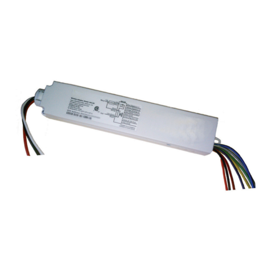
The Daintree WA100-PM Wireless Adapter forms part of the Daintree ControlScope wireless controls solution for smart
commercial and industrial buildings. It transmits and receives messages over the wireless ZigBee
The WA100-PM is an AC powered device that provides On/Off switching as well as 0-10V analog dimming control for
LED drivers and ballasts.* It also provides power for low voltage occupancy sensors, photosensors (daylight harvesters),
wall switches, and control signals while it provides the wireless adaptation that enables them to communicate with the
rest of the wireless control solution. The control signals to and from these connected devices pass between the WA100-PM
and the Wireless Area Controller in ControlScope Manager (CSM), the Daintree management app.
Installation Process
1. Disconnect power before installation. Turn off all
power to affected light fixtures by turning off circuit
breakers. Confirm that power is off at all light fixtures
before continuing installation.
2. Set the WA100-PM DIP switches to support the device(s)
being connected to it . See
3. IMPORTANT: Affix the small label with 4-5 digits of the
WA100-PM's IEEE address on the floor Plan to indicate
its location.
4. Mount the WA100-PM in the driver cavity of the light
fixture, or external to the light fixture, or to a junction box
approved for the application. See
5. Connect low voltage wiring from the WA100-PM to the
driver, switch(es) and/or sensors as appropriate for your
application. See
6. Connect line voltage wires from the supply circuit to the
WA100-PM and to the driver as shown in
unused wire.
7. Check load circuits then turn on the circuit breakers
to power up the WA100-PM. The light connected to the
WA100-PM turns On when power is initially applied (and
when power is restored after a power failure).
8. Ensure the WA100-PM green Power
9. Press and hold the blue RESET button on the WA100-PM
for 3 seconds to reset the unit. Release the button when the
green Joined
LED and the red Error
10. Perform the installation test appropriate for your
application. See
DT113 (Rev. 12.8.17)
(pages 2-3).
(page 13).
(pages 4-11). Cap any unused wires.
Wiring.
LED is On.
LEDs begin flashing.
(pages 14-16) .
LED Indicators
Error—On when the Wireless Adapter is in an error state.
Flashes once per second to indicate DIP Switch
configuration error. Flashes to indicate unit Reset
and during Installation Test Mode (red).
Joined—On when the Wireless Adapter has joined a
ZigBee
sensor Installation Test Mode (green).
Power—On when power is applied to the Wireless
Adapter (green).
Cap any
network and controls lights.
®
network. Flashes to indicate Reset and during
®
RESET
Error
Joined
Power
Reset
LED
LED
LED
1
Advertisement
Table of Contents

Related Manuals for Current WA100-PM

Summary of Contents for Current WA100-PM
-
Page 1: Installation Process
® The WA100-PM is an AC powered device that provides On/Off switching as well as 0-10V analog dimming control for LED drivers and ballasts.* It also provides power for low voltage occupancy sensors, photosensors (daylight harvesters), wall switches, and control signals while it provides the wireless adaptation that enables them to communicate with the rest of the wireless control solution. -
Page 2: Dip Switch Settings
Wireless Adapter (WA100-PM) WA100-PM Model Variants The model number WA100 was the original version of the adapter and is no longer sold. The WA100-PM model monitors and WA100-PM measures the power consumption of the connected lighting load. The reports power measurement data to CSM. - Page 3 To provide wireless adaptation for sensors, set DIP switches 1, 5 & 6 according to the type(s) of sensors connected to the WA100-PM. Range Extender The WA100-PM joins the ZigBee network and acts only as a wireless repeater to improve the wireless range and/ or reliability. No lights or devices are connected to the WA100-PM. Switch Adapter Mode Switch Type Dimming: operating the connected switch generates dimming and On/Off signals.
- Page 4 While the WA100-PM is in Installation Test mode the low voltage devices connected to the WA100-PM directly control the lights wired to the same WA100-PM. After you exit Installation Test mode, the lights turn On and are NOT controlled by the devices connected to the WA100-PM.
- Page 5 All installation and maintenance of line voltage equipment must be performed by a qualified electrician. • The WA100-PM must be installed in accordance with all local, state, and national electrical codes and requirements. • Wiring connectors are not supplied. UL recognized wiring connectors must be used in...
- Page 6 Wireless Adapter (WA100-PM) Fig. 4: Dimming Light Fixtures: DIP Switches Driver type: Wired ↓ DIP Switch Positions: Sensor: On/Off + 0-10V 1 2 3 4 5 6 None dimming ( a l l O F F ) WHITE Neutral BLACK Hot 120-277VAC...
- Page 7 Wireless Adapter (WA100-PM) Fig. 5: On/Off (non-dimming) Light Fixtures: This configuration allows the WA100-PM to provide automatic On/Off switching of light fixtures. DIP Switches Wired Driver type: ↓ DIP Switch Positions: Sensor: On/Off (no dimming) 1 2 3 4 5 6...
- Page 8 Wireless Adapter (WA100-PM) Fig. 6: On/Off (non-dimming) Light Fixture(s), Occupancy Sensor configuration: This configuration allows the WA100-PM to provide automatic On/Off switching based on occupancy. Set occupancy sensor for minimum time delay. DIP Switches Wired Driver type: ↓ Sensor: DIP Switch Positions:...
- Page 9 Wireless Adapter (WA100-PM) Fig. 7: Dimming Driver(s), Occupancy Sensor configuration: This configuration allows the WA100-PM to provide automatic 0-10V dimming control and to switch drivers On/Off based on occupancy. Set occupancy sensor for minimum time delay. DIP Switches Driver type: Wired ↓...
- Page 10 Wireless Adapter (WA100-PM) Fig. 8: Dimming Light Fixture(s), Photosensor configuration: This configuration allows the WA100-PM to provide automatic 0-10V dimming control and to switch light fixtures On/Off. DIP Switches Driver: Wired Sensor: ↓ DIP Switch Positions: On/Off + 0-10V Photosensor...
- Page 11 Wireless Adapter (WA100-PM) Fig. 9: Dimming Light Fixture(s), Photosensor, Occupancy Sensor configuration: This configuration allows the WA100-PM to provide automatic 0-10V dimming control and to switch drivers On/Off. Set occupancy sensor for minimum time delay. DIP Switches Driver: Wired Sensor: ↓...
- Page 12 Wireless Adapter (WA100-PM) Fig. 10: Dimming Light Fixture(s) and Switch configuration: This configuration allows the WA100-PM to provide 0-10V dimming control and to switch light fixtures On/Off. It also provides manual On/Off control through a low voltage momentary contact switch.
- Page 13 Wireless Adapter (WA100-PM) Fig. 11: Bi-level Switching: This configuration allows the WA100-PM to switch loads independently in a bi-level driver (or 2 drivers), providing no load (0%), partial load (according to the driver/ballast capability) or full load (100%). DIP Switches...
- Page 14 Wireless Adapter (WA100-PM) Fig. 12: Alternate Switching: This configuration allows the WA100-PM to alternate in switching separate drivers, providing no load (0%), partial load (according to the driver loading) or full load (100%). Always connect the smaller proportion of the total load to the WA100-PM’s RED Switched Load wire.
- Page 15 Wireless Adapter (WA100-PM) Fig. 13: Switching a Branch Circuit: This configuration allows the WA100-PM to provide On/Off switching of a branch circuit . DIP Switches Wired Driver type: ↓ DIP Switch Positions: Sensor: On/Off (no dimming) 1 2 3 4 5 6...
- Page 16 Wireless Adapter (WA100-PM) Fig. 14: 208V 2-Pole (Phase-to-Phase) wiring This configuration allows the WA100-PM to provide On/Off switching of a branch circuit . DIP Switches Wired Driver type: ↓ DIP Switch Positions: Sensor: On/Off (no dimming) 1 2 3 4 5 6...
- Page 17 Wireless Adapter (WA100-PM) Fig. 15: Switching Contactors: This configuration allows the WA100-PM to provide On/Off switching control to an external contactor. DIP Switches Wired Driver type: ↓ DIP Switch Positions: Sensor: On/Off (no dimming) 1 2 3 4 5 6...
- Page 18 Fig. 16: Bypass WA100 switched power and 0-10V dimming control during power failure In the wiring diagram here, while Regular power is supplied to the LVS model RRU-X-UM the WA100-PM provides switched On/Off power and 0-10V dimming control to the fixture driver or ballast .
- Page 19 Fig. 17: Emergency and Regular Light Fixtures: Wiring to Dim while Regular Power is Available In this application, the WA100-PM is powered by the Regular power circuit and is installed inside the Regular Light Fixture. While Regular power is supplied to the RRU-2 the WA100-PM provides switched On/Off power to the Regular Light Fixture.
- Page 20 1. Make sure the unit is NOT powered. 2. Cut the unused low voltage wires approximately five inches from where they exit the WA100-PM body. 3. Isolate the end of each wire using a wire nut , shrink tubing, or equivalent .
- Page 21 Wireless Adapter (WA100-PM) Mounting Fig. 19: Mounting in driver channel The WA100-PM is designed so that it can be mounted in a variety of ways. Depending on the construction of the fixture and its ability to propagate radio signals, it can be mounted inside the fixture in the ballast/driver channel.
- Page 22 If you have not already done so, be sure that each WA100-PM’s IEEE address (last 4 or 5 digits) is recorded on the facility floor plan. You can use the 4 or 5 digit label supplied with the WA100-PM or you can write the last 4 or 5 digits on the floor plan.
- Page 23 Off. 5. Press and immediately release the Reset button to exit testing. 6. Press and hold the blue RESET button on the WA100-PM for 3 seconds to reset the unit . Release the button when the green Joined LED and the red Error LEDs begin flashing.
- Page 24 4. Operate the switch(es) connected to the WA100-PM and observe that the lights turn On, Off, and Dim as expected. 5. Press and immediately release the Reset button to exit testing. 6. Press and hold the blue RESET button on the WA100-PM for 3 seconds to reset the unit . Release the button when the green Joined LED and the red Error LEDs begin flashing.
- Page 25 Shine a bright light at the photosensor – the light turns On. 6. Press and immediately release the Reset button to exit testing. 7. Press and hold the blue RESET button on the WA100-PM for 3 seconds to reset the unit . Release the button when the green Joined LED and the red Error LEDs begin flashing.
-
Page 26: Troubleshooting
(WAC) and the Daintree ControlScope Manager (CSM) web-based lighting management user interface. Upon commissioning, the WA100-PM “Join” LED turns on solid and remains on as long as the WA100-PM is included in the ZigBee Network. After joining the network, the low voltage devices connected to the WA100-PM do not directly control the lights that are wired to the same WA100-PM. - Page 27 GE is a trademark of the General Electric Company. All other trademarks are the property of their respective owners. Information provided is subject to change without notice. All values are design or typical values when measured under laboratory conditions. Current and GE Lighting are businesses of the General Electric Company. © 2017 GE...
- Page 28 Appendix 1: Installation Advisory - Plug Load Applications (WA100-PM) Plug load control functionality for the WA100-PM is made available with WA100-PM firmware provided in ControlScope Manager version 3.5.3.1. During testing the Plug Load cycles on/off in sync with the lighting load. Relays used to control plug loads must be compliant with UL498 (Attachment Plug and Receptacles) or equivalent.
- Page 29 1 2 3 4 5 6 Plug Load: On/Off None In the wiring diagram below, the WA100-PM is used to (# 2, 3 ON ) control both a dimming light and a plug load circuit. Perform Installation Test Suite 1...
- Page 30 GE is a trademark of the General Electric Company. All other trademarks are the property of their respective owners. Information provided is subject to change without notice. All values are design or typical values when measured under laboratory conditions. Current and GE Lighting are businesses of the General Electric Company. © 2017 GE...
Need help?
Do you have a question about the WA100-PM and is the answer not in the manual?
Questions and answers