
Related Manuals for Extreme Networks ExtremeSwitching 210-12t-GE2


Summary of Contents for Extreme Networks ExtremeSwitching 210-12t-GE2
- Page 1 ExtremeSwitching 210 and 220 Series Switches: Hardware Installation Guide 122039-00 Published May 2017...
-
Page 2: Legal Notice
Copyright © 2017 Extreme Networks, Inc. All rights reserved. Legal Notice Extreme Networks, Inc. reserves the right to make changes in specifications and other information contained in this document and its website without prior notice. The reader should in all cases consult representatives of Extreme Networks to determine whether any such changes have been made. -
Page 3: Table Of Contents
Table of Contents Preface............................5 Audience....................................5 Conventions..................................... 5 Providing Feedback to Us..............................6 Getting Help.....................................7 Related Publications................................7 Chapter 1: ExtremeSwitching 210 and 220 Series Switches..........9 Overview of the ExtremeSwitching 210 Series Switches.................10 Overview of the ExtremeSwitching 220 Series Switches................16 ExtremeSwitching 210 and 220 Series Switch LEDs..................23 Pluggable Interfaces for ExtremeSwitching Switches..................23 Chapter 2: External Power Supplies..................25... - Page 4 Table of Contents Power Cord Requirements for AC-Powered Switches and AC Power Supplies........77 Index............................79 ExtremeSwitching 210 and 220 Series Switches: Hardware Installation Guide...
-
Page 5: Preface
• Basic equipment installation procedures Note If the information in an installation note or release note shipped with your Extreme Networks equipment differs from the information in this guide, follow the installation or release note. Conventions This section discusses the conventions used in this guide. -
Page 6: Providing Feedback To Us
Preface Table 1: Notice Icons Icon Notice Type Alerts you to... General Notice Helpful tips and notices for using the product. Note Important features or instructions. Caution Risk of personal injury, system damage, or loss of data. Warning Risk of severe personal injury. This command or section is new for this release. -
Page 7: Getting Help
Preface If you would like to provide feedback to the Extreme Networks Information Development team about this document, please contact us using our short online feedback form. You can also email us directly at internalinfodev@extremenetworks.com. Getting Help If you require assistance, contact Extreme Networks using one of the following methods: •... - Page 8 Preface Open Source Declarations Some software files have been licensed under certain open source licenses. More information is available at: www.extremenetworks.com/support/policies/software-licensing ExtremeSwitching 210 and 220 Series Switches: Hardware Installation Guide...
-
Page 9: Chapter 1: Extremeswitching 210 And 220 Series Switches
• Has 48 ports of copper providing PoE. • Has four ports that can transmit at 10GbE speed. The following sections provide detailed descriptions of the switches: • ExtremeSwitching 210-12t-GE2 switch • ExtremeSwitching 210-12p-GE2 switch • ExtremeSwitching 210-24t-GE2 switch •... -
Page 10: Overview Of The Extremeswitching 210 Series Switches
Switch cooling is provided by one, two, or three non-replaceable fan modules with side-to-side airflow. AC power is supplied by a built-in power supply unit that is not user-replaceable. ExtremeSwitching 210-12t-GE2 Switch Ports and Slots The ExtremeSwitching 210-12t-GE2 switch ports and slots include: • 12 10/100/1000BASE-T ports (ports 1–12) that provide 1 GbE connectivity •... - Page 11 ExtremeSwitching 210 and 220 Series Switches Figure 1: ExtremeSwitching 210-12t-GE2 Switch Front Panel 1 = Ethernet management port 3 = 10/100/1000BASE-T ports 2 = Console port 4 = SFP ports Figure 2: ExtremeSwitching 210-12t-GE2 Switch Rear Panel 1 = Grounding point...
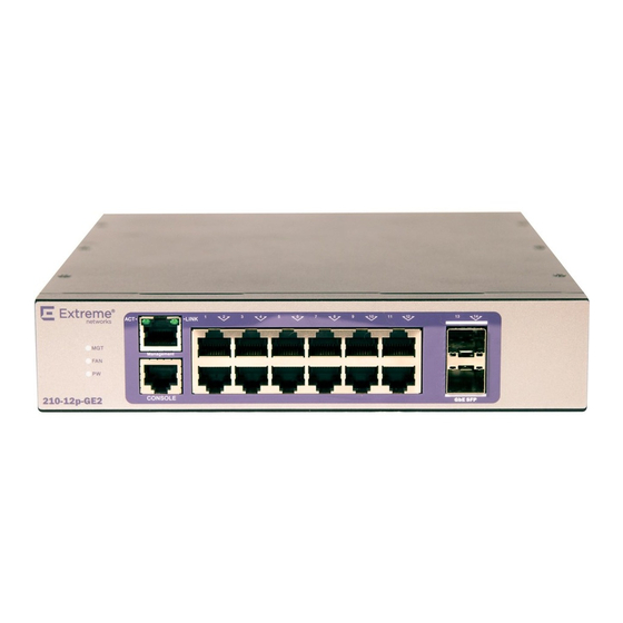
- Page 12 ExtremeSwitching 210 and 220 Series Switches For a description of the LEDs and their operation, see ExtremeSwitching 210 and 220 Series Switch LEDs on page 23. Figure 3: ExtremeSwitching 210-12p-GE2 Switch Front Panel 1 = Ethernet management port 3 = 10/100/1000BASE-T ports 2 = Console port 4 = SFP ports Figure 4: ExtremeSwitching 210-12p-GE2 Switch Rear Panel...
- Page 13 ExtremeSwitching 210 and 220 Series Switches • Serial console port used to connect a terminal and perform local management • LEDs to indicate switch operating conditions For a description of the LEDs and their operation, see ExtremeSwitching 210 and 220 Series Switch LEDs on page 23.
- Page 14 ExtremeSwitching 210 and 220 Series Switches Figure 7: ExtremeSwitching 210-24p-GE2 Switch Front Panel 1 = Ethernet management port 3 = 10/100/1000BASE-T ports 2 = Console port 4 = SFP ports Figure 8: ExtremeSwitching 210-24p-GE2 Switch Rear Panel 1 = Grounding point 2 = AC power input connector ExtremeSwitching 210-48t-GE4 Switch Ports and Slots The ExtremeSwitching 210-48t-GE4 switch ports and slots include:...
- Page 15 ExtremeSwitching 210 and 220 Series Switches Figure 9: ExtremeSwitching 210-48t-GE4 Switch Front Panel 1 = Ethernet management port 3 = 10/100/1000BASE-T ports 2 = Console port 4 = SFP ports Figure 10: ExtremeSwitching 210-48t-GE4 Switch Rear Panel 1 = Grounding point 2 = AC power input connector ExtremeSwitching 210-48p-GE4 Switch Ports and Slots The ExtremeSwitching 210-48p-GE4 switch ports and slots include:...
-
Page 16: Overview Of The Extremeswitching 220 Series Switches
ExtremeSwitching 210 and 220 Series Switches Figure 11: ExtremeSwitching 210-48p-GE4 Switch Front Panel 1 = Ethernet management port 3 = 10/100/1000BASE-T ports 2 = Console port 4 = SFP ports Figure 12: ExtremeSwitching 210-48p-GE4 Switch Rear Panel 1 = Grounding point 2 = AC power input connector Overview of the ExtremeSwitching 220 Series Switches The ExtremeSwitching 220 series switches are 12-, 24, or 48-port switches that provide 10-gigabit... - Page 17 ExtremeSwitching 210 and 220 Series Switches The 12-port switches have a small form factor that allows you to install two switches side-by-side in a standard equipment rack. Switch cooling is provided by one, two, or three non-replaceable fan modules with side-to-side airflow. AC power is supplied by a built-in power supply unit that is not user-replaceable.
- Page 18 ExtremeSwitching 210 and 220 Series Switches Figure 14: ExtremeSwitching 220-12t-10GE2 Switch Rear Panel 1 = Grounding point 2 = AC power input connector ExtremeSwitching 220-12p-10GE2 Switch Ports and Slots The ExtremeSwitching 220-12p-10GE4 switch ports and slots include: • 12 10/100/1000BASE-T PoE+ ports (ports 1–12) that provide 1 GbE connectivity •...
- Page 19 ExtremeSwitching 210 and 220 Series Switches 2 = Console port 4 = 10 GbE SFP+ ports Figure 16: ExtremeSwitching 220-12p-10GE2 Switch Rear Panel 1 = Grounding point 2 = AC power input connector ExtremeSwitching 220-24t-10GE2 Switch Ports and Slots The ExtremeSwitching 220-24t-10GE2 switch ports and slots include: •...
- Page 20 ExtremeSwitching 210 and 220 Series Switches Figure 18: ExtremeSwitching 220-24t-10GE2 Switch Rear Panel 1 = Redundant power input 3 = AC power input connector 2 = Grounding point ExtremeSwitching 220-24p-10GE2 Switch Ports and Slots The ExtremeSwitching 220-24p-10GE2 switch ports and slots include: •...
- Page 21 ExtremeSwitching 210 and 220 Series Switches Figure 20: ExtremeSwitching 220-24p-10GE2 Switch Rear Panel 1 = Redundant power input 3 = AC power input connector 2 = Grounding point ExtremeSwitching 220-48t-10GE4 Switch Ports and Slots The ExtremeSwitching 220-48t-10GE4 switch ports and slots include: •...
- Page 22 ExtremeSwitching 210 and 220 Series Switches Figure 22: ExtremeSwitching 220-48t-10GE4 Switch Rear Panel 1 = Redundant power input 3 = AC power input connector 2 = Grounding point ExtremeSwitching 220-48p-10GE4 Switch Ports and Slots The ExtremeSwitching 220-48p-10GE4 switch ports and slots include: •...
-
Page 23: Extremeswitching 210 And 220 Series Switch Leds
Some 210 and 220 series switches include ports that are compatible with a variety of optical modules, including SFP and SFP+ modules. Extreme Networks optical modules are tested to work in all supported Extreme Networks devices. We recommend that all customers use Extreme Networks optical modules in their Extreme Networks devices. - Page 24 ExtremeSwitching 210 and 220 Series Switches operate properly in all Extreme Networks devices. The customer assumes all risks associated with using third-party optical modules in Extreme Networks devices. For more information, refer to the Extreme Networks Pluggable Transceivers Installation Guide.
-
Page 25: Chapter 2: External Power Supplies
28. RPS-150XT Redundant Power Supply The RPS-150XT provides backup power to Extreme Networks stackable switches. If for some reason the switch loses power from its internal power supply, the RPS-150XT can provide up to 150 W maximum operating power to support switch operation. - Page 26 External Power Supplies • ExtremeSwitching X440-G2-24t-GE4 switch • ExtremeSwitching X620-8t-2x switch • ExtremeSwitching X620-10x switch The RPS-150XT is compatible with the following Extreme Networks switches: • ExtremeSwitching 220-24t-10GE2 switch • ExtremeSwitching 220-48t-10GE4 switch Figure 25: RPS-150XT Front Panel 1 = Captive screws...
-
Page 27: Rps-500P Redundant Power Supply
Four rubber feet (for flat surface installation) • Two rack mount brackets • Eight flathead screws (M3x6mm) The RPS-500p is compatible with the following Extreme Networks switches: • Summit X440 switches (all models that are compatible with external power supplies) • ExtremeSwitching X440-G2 switches (most models) •... -
Page 28: Installing External Power Supplies
External Power Supplies Installing External Power Supplies Read the information in the following sections thoroughly before you start to install or remove an external power supply. Installing an RPS-150XT Redundant Power Supply You can install the RPS-150XT power supply on a flat surface or in a 19-inch rack in the three-slot modular shelf (STK-RPS-1005CH3), which is available for purchase separately. - Page 29 External Power Supplies To install the RPS-150XT in a rack, follow these steps. Secure the front of the three-slot modular shelf (STK-RPS-1005CH3) to the rack by screwing four rack screws into the mounting ears on the right and left front of the shelf. Figure Figure 27: Securing the Three-slot Modular Shelf to a Rack 2 Slide the power supply into an empty bay in the shelf.
- Page 30 External Power Supplies Installing an RPS-150XT on a Flat Surface Caution Observe all Electrostatic Discharge (ESD) precautions when handling sensitive electronic equipment. When installing the RPS-150XT power supply on a flat surface, we recommend installing the rubber feet to prevent the power supply from sliding. Note Do not install the rubber feet on the power supply if you are installing the power supply in the three-slot modular shelf (STK-RPS-1005CH3).
- Page 31 External Power Supplies Figure 29: RPS Cable and AC Power Cord Connections for the RPS-150XT 1 = Switch 4 = Redundant Power Supply connector 2 = RPS cable 5 = AC power cord 3 = RPS-150XT 6 = AC power outlet with ground connection Note AC power cords and outlets vary depending on country.
- Page 32 External Power Supplies Installing an RPS-500p Redundant Power Supply You can install the RPS-500p power supply on a flat surface or in a 19-inch rack. Caution Observe all Electrostatic Discharge (ESD) precautions when handling sensitive electronic equipment. Locate the RPS-500p within 6 ft (1.8 m) of its power source. Only qualified personnel should install redundant power supply (RPS) units.
- Page 33 External Power Supplies Figure 30: Attaching the Rack-Mounting Brackets 1 = Rack-mounting brackets (2) 2 = M3x6mm flathead screws (8) 2 With the rack-mounting brackets attached, position the RPS-500p between the vertical rack rails of the 19-inch rack as shown in Figure Figure 31: Fastening the RPS-500p to the Rack 1 = RPS-500p...
- Page 34 External Power Supplies 4 If you are installing the RPS-500p in a stacked configuration, repeat this procedure for each power supply. 5 Connect the RPS-500p to its power source. Connecting the RPS Cable and AC Power Cord to an RPS-500p on page 34.
- Page 35 External Power Supplies Figure 32: RPS Cable and AC Power Cord Connections for the RPS-500p 1 = PoE-compliant switch 4 = Redundant Power Supply connector on switch 2 = RPS cable 5 = AC power cord 3 = Redundant Power Supply connector on power supply 6 = AC power outlet with ground connection Note AC power cords and outlets vary depending on country.
-
Page 36: Chapter 3: Installing Your 210 Or 220 Switch
Installing a Switch on a Desktop or Other Flat Surface Installing Optional Components Connecting Power to the Switch Connecting Network Interface Cables Before you attempt to install or remove an Extreme Networks switch, read the precautions in Safety Considerations for Installing Switches on page 37. -
Page 37: Safety Considerations For Installing Switches
Installing Your 210 or 220 Switch Safety Considerations for Installing Switches Read the information in this chapter thoroughly before you attempt to install or remove an Extreme Networks switch. Caution Be sure that proper ESD controls are in use before switch maintenance is performed. This includes but is not limited to wrist straps that are grounded to the switch chassis and earth grounds. -
Page 38: Attaching A 24- Or 48-Port Switch To A Rack
Installing Your 210 or 220 Switch Attaching a 24- or 48-Port Switch to a Rack Before you begin the installation, refer to Pre-installation Requirements on page 37. To mount your 210 or 220 series switch in a two-post rack, follow these steps. For 12-port switches, see Mounting 12-Port Switches on page 39. -
Page 39: Mounting 12-Port Switches
Connect power to the switch. See Connecting Power to the Switch on page 50. Mounting 12-Port Switches The instructions in this section pertain to the following switch models: • ExtremeSwitching 210-12t-GE2 switch • ExtremeSwitching 210-12p-GE2 switch • ExtremeSwitching 220-12t-10GE2 switch •... - Page 40 No. 1 Phillips screwdriver for attaching bracket hardware (a magnetic screwdriver is recommended) • Flat-head screwdriver for mounting the switch in the rack The instructions in this section pertain to the following switch models: • ExtremeSwitching 210-12t-GE2 switch • ExtremeSwitching 210-12p-GE2 switch • ExtremeSwitching 220-12t-10GE2 switch •...
- Page 41 No. 1 Phillips screwdriver for attaching bracket hardware (a magnetic screwdriver is recommended) • Flat-head screwdriver for mounting the switches in the rack The instructions in this section pertain to the following switch models: • ExtremeSwitching 210-12t-GE2 switch • ExtremeSwitching 210-12p-GE2 switch • ExtremeSwitching 220-12t-10GE2 switch •...
- Page 42 Installing Your 210 or 220 Switch 2 Attach mounting hardware to the first switch. a Using four chassis screws, attach a short bracket to the left side of the switch. Figure Figure 36: Dual-Mount: Attaching a Short Bracket to the First Switch ExtremeSwitching 210 and 220 Series Switches: Hardware Installation Guide...
- Page 43 Installing Your 210 or 220 Switch b Using four chassis screws, attach the long middle-support bracket to the right side of the switch. Figure Figure 37: Dual-Mount: Attaching the Long Middle-Support Bracket to the First Switch ExtremeSwitching 210 and 220 Series Switches: Hardware Installation Guide...
- Page 44 Installing Your 210 or 220 Switch 3 Attach mounting hardware to the second switch. a Using two chassis screws, attach a short middle-support bracket to the left side of the switch, at the front end. Position the bracket so that the tab end is toward the front of the switch. See Figure Figure 38: Dual-Mount: Attaching the Middle-Support Brackets to the Second Switch...
- Page 45 Installing Your 210 or 220 Switch Figure 39: Dual-Mount: Attaching the Connecting Brackets to Each Other The switches can now be handled as if they were a single unit, as shown in Figure Figure 40: Two Switches Connected to Each Other for Dual Mounting 6 Attach the switches to the rack using rack-mounting hardware (not provided).
- Page 46 No. 1 Phillips screwdriver for attaching bracket hardware (a magnetic screwdriver is recommended) • Flat-head screwdriver for mounting the switches in the rack The instructions in this section pertain to the following switch models: • ExtremeSwitching 210-12t-GE2 switch • ExtremeSwitching 210-12p-GE2 switch • ExtremeSwitching 220-12t-10GE2 switch •...
- Page 47 Installing Your 210 or 220 Switch 4 Using four chassis screws, attach a wall-mounting bracket to the left side of the switch, at the front end. Figure Figure 41: Wall-Mount: Attaching a Wall-Mounting Bracket 5 In the same way, attach a wall-mounting bracket to the right side of the switch. Caution Two people should perform the following steps: one to hold the switch in place and one to attach it to the wall.
-
Page 48: Installing A Switch On A Desktop Or Other Flat Surface
Installing Your 210 or 220 Switch 6 Mount the switch assembly on the wall by screwing an anchor screw through each hole in the wall- mounting brackets into the anchors. Figure Figure 42: Wall-Mount: Mounting the Switch on the Wall 7 Check that all screws have been securely fastened and that the switch is firmly attached to the wall. -
Page 49: Installing Optional Components
Installing Your 210 or 220 Switch The pads keep the switch from scratching the supporting surface and help ensure adequate airflow around the switches when they are mounted on top of one another. You can safely place up to four switches on top of one another. -
Page 50: Pluggable Transceiver Modules
Installing Your 210 or 220 Switch Pluggable Transceiver Modules Extreme Networks offers several optical transceiver modules for transmitting and receiving data over optical fiber rather than through electrical wires. Install these modules using the instructions in Extreme Networks Pluggable Transceivers Installation Guide. - Page 51 Installing Your 210 or 220 Switch Set up local management access, and configure the switch's software, by following the instructions in Basic Configuration for Your Switch on page 60. ExtremeSwitching 210 and 220 Series Switches: Hardware Installation Guide...
-
Page 52: Chapter 4: Building Stacks
Building Stacks Planning to Create Your Stack Setting up the Physical Stack Managing Stacks A stack consists of a group of up to four 220 series switches that are connected to form a logical ring. The stack offers the combined port capacity of the individual switches – but it operates as if it were a single switch, making network administration easier. - Page 53 Building Stacks For more information about specialized terms used for stacking, see Stacking Terms on page 53. Stacking Terms Table 7 describes common terms used when stacking 220 series switches. The terms are listed in the recommended reading sequence. Table 7: List of Stacking Terms Term Description Stackable switch or Unit...
-
Page 54: Stacking Cables
53 for physically situating your equipment. Stacking Cables Connections between switches in a stack require stacking cables. These cables are available from Extreme Networks in varying lengths. You can use the following cables as stacking connectors for 220 series switches. •... -
Page 55: Setting Up The Physical Stack
SFP+ pluggable copper cable, 3 meters (part number 10GB-C03-SFPP) Caution Use of non-recommended cables or optics could cause stack instability. For the most recent information about available cables, contact your Extreme Networks sales representative or refer to Extreme Hardware/Software Compatibility and Recommendation Matrices. - Page 56 Building Stacks Examples of Stacking Configurations Here are some sample stacking configurations for 220 series switches. Note In each example, the stacks consist of 48-port switches and connections are made through SFP+ ports 49 and 50. If you are stacking 24-port switches, make the connections through SFP+ ports 25 and 26. If you are stacking 12-port switches, make the connections through SFP+ ports 13 and 14.
- Page 57 Building Stacks Stacked Switches Across Two Racks The following example shows four switches physically located in two adjacent racks. In this example, start by connecting the top switches together (slots 1 and 2). The first switch you power on will be designated the stack manager, and the second will be the standby. Figure 45: Cable Connections for Four Switches in Two Racks Table 9 lists the recommended order for connecting the stacking ports in this example.
-
Page 58: Managing Stacks
Building Stacks Table 10: Stacked Switches Across Several Racks: Recommended Connections (48- Port Switches) Connect this slot and port ..To this slot and port Slot 1 Rack A Port 50 Slot 2 Rack B Port 49 Slot 2 Rack B... - Page 59 Building Stacks • Merging two operational stacks • Preconfiguring stack units ExtremeSwitching 210 and 220 Series Switches: Hardware Installation Guide...
-
Page 60: Chapter 5: Basic Configuration For Your Switch
Basic Configuration for Your Switch First-time Network Connection and Configuration When you set up a switch for the first time, you must connect to the console to access the switch and perform initial security configuration. You can also: • Download and configure the operating-system software for the switch. •... - Page 61 Basic Configuration for Your Switch 6 Optionally, open the web interface. a Open a web browser and enter the IP address of the switch in the browser's address field. b Type the user name and password into the fields on the login screen, then click Login. The user name and password are the same as those you use to log on to the command-line interface.
- Page 62 Basic Configuration for Your Switch • To view the network information, enter show network • To save these changes so they are retained during a switch reset, enter the following command: copy system:running-config nvram:startup-config For details, see the ExtremeSwitching 200 Series Switches Administration Guide.
-
Page 63: Appendix A: Safety Information
Only trained and qualified service personnel (as defined in IEC 60950-1 and AS/NZS 3260) should install, replace, or perform service to Extreme Networks switches and their components. Qualified personnel have read all related installation manuals, have the technical training and experience necessary to be aware of the hazards to which they are exposed in performing a task, and are aware of measures to minimize the danger to themselves or other persons. -
Page 64: General Safety Precautions
Make sure that your power supplies meet the site DC power or AC power requirements of all the network equipment. • Racks for Extreme Networks equipment must be permanently attached to the floor. Failure to stabilize the rack can cause the rack to tip over when the equipment is removed for servicing. •... -
Page 65: Cable Routing For Lan Systems
OSP wiring. Selecting Power Supply Cords Extreme Networks does not include power input cords in the product box. A power input cord is included in the product packaging for your switch .If additional cords are needed, you can obtain them as follows. -
Page 66: Battery Replacement And Disposal
Battery Warning - Taiwan Fiber Optic Ports and Optical Safety The following safety warnings apply to all optical devices used in Extreme Networks equipment that are removable or directly installed in an I/O module or chassis system. ExtremeSwitching 210 and 220 Series Switches: Hardware Installation Guide... - Page 67 Never alter, modify, or change an optical device in any way other than suggested in this document. GBIC, SFP (Mini-GBIC), QSFP+, XENPAK, and XFP Regulatory Compliance Extreme Networks pluggable optical modules and direct-attach cables meet the following regulatory requirements: •...
-
Page 68: Appendix B: Technical Specifications
The following sections contain technical specifications for the ExtremeSwitching 210 series switches, 220 series switches, and supported external power supplies. ExtremeSwitching 210 and 220 Switches The ExtremeSwitching 210 series includes the following switches: • ExtremeSwitching 210-12t-GE2 switch • ExtremeSwitching 210-12p-GE2 switch • ExtremeSwitching 210-24t-GE2 switch •... - Page 69 Technical Specifications Table 11: Physical Dimensions (Unpackaged) (continued) 220-12t-10GE2 Height: 4.30 cm (1.69 in) 220-12p-10GE2 Width: 20.90 cm (8.23 in) Length: 25.50 cm (10.05 in) 220-24t-10GE2 Height: 4.40 cm (1.73 in) 220-24p-10GE2 Width: 44.10 cm (17.38 in) 220-48t-10GE4 Length: 25.40 cm (10.01 in) 220-48p-10GE4 Table 12: Weight (Unpackaged) 210-12t-GE2...
- Page 70 Technical Specifications Table 14: Weight (Packaged) 210-12t-GE2 2.02 kg (4.45 lb) 210-12p-GE2 2.44 kg (5.38 lb) 210-24t-GE2 4.01 kg (8.84 lb) 210-24p-GE2 4.56 kg (10.05 lb) 210-48t-GE4 5.35 kg (11.79 lb) 210-48p-GE4 4.59 kg (10.12 lb) 220-12t-10GE2 2.02 kg (4.45 lb) 220-12p-10GE2 2.39 kg (5.27 lb) 220-24t-10GE2...
- Page 71 Technical Specifications Table 16: Power Consumption and Dissipation Switch Model Heat Dissipation Power Consumption Heat Dissipation Power Consumption (Minimum) (Minimum) (Maximum) (Maximum) 210-12t-GE2 10.5 W, 35.83 BTU/hr 10.5 W 18.4 W, 62.78 BTU/hr 18.4 W 210-12p-GE2 16.4 W, 55.96 BTU/hr 16.4 W 25 W, 85.30 BTU/hr 25 W...
- Page 72 Technical Specifications Table 17: Temperature and Acoustical Sound (continued) Switch Model Temperature Fan Speed Number Sound Sound Declared of Fans Pressure Power Sound (dBA) (dBA) Power (BA) 210-12p-GE2 0°-35°C (32°-95°F) 18.7 26.7 220-12p-10GE2 35°-45°C (95°-113°F) 37.5 48.0 45°-50°C (113°-122°F) high 50.1 60.6 210-24t-GE2...
- Page 73 Technical Specifications Table 20: EMI/EMC Standards North America EMC for ITE FCC CFR 47 part 15 Class A (USA) ICES-003 Class A (Canada) European EMC standards EN 55032:2012 EN 55024:1998+A1:2001+A2:2003 Class A includes IEC 61000-4-2, 3, 4, 5, 6, 11 EN 61000-3-2: 2006+A2:2009 (Harmonics) EN 61000-3-3:2008 (Flicker) ETSI EN 300 386: v1.4.1 (2008-04) (EMC Telecommunications)
-
Page 74: Rps-150Xt Redundant Power Supply Technical Specifications
Technical Specifications Table 23: Environmental Data Environmental standards EN/ETSI 300 019-2-1 v2.1.2 (2000 - 2009) - Class 1.2 Storage EN/ETSI 300 019-2-2 v2.1.2 (1999 - 09) - Class 2.3 Transportation EN/ETSI 300 019-2-3 v2.1.2 (2003 - 04) - Class 3.1e Operational EN/ETSI 300 753 (1997-10) - Acoustic Noise ASTM D3580 Random Vibration Unpackaged 1.5G Operating conditions... - Page 75 Technical Specifications Table 26: Environmental Specifications Operating temperature 0°C to 60°C (32°F to 140°F) Storage temperature -45°C to 85°C (-49°F to 185°F) Operating relative humidity 10% to 90% operating/95% non-condensing RPS-150XT Connector Figure 47 Table 27 on page 75or pin locations and function. Note The following information is for troubleshooting purposes only.
-
Page 76: Rps-500P Redundant Power Supply Technical Specifications
Technical Specifications Table 27: RPS-150XT Connector Pin Functions (continued) Function Function 12 V power Start 2 12 V power Power good Ground Ground RPS-500p Redundant Power Supply Technical Specifications External Power Supplies for PoE Switches The following tables list the specifications for the 500 W DC RPS-500p (model 10923). Table 28: Physical Specifications Dimensions 4.45 H x 44.5 W x 16.5 D (cm) 1.75 H x 17.5 W x 6.5 D (in) - Page 77 Technical Specifications RPS-500p Connector Figure 48 Table 31 on page 77 for pin locations and function. Note The following information is for troubleshooting purposes only. For proper operation, use only the 1 meter RPS cable supplied with the RPS-500p. This cable is specially designed for this application and meets all necessary regulatory and safety standards.
- Page 78 The power cords for switches that use either the 1100 W or 715 W power supplies are keyed with a “notch” to ensure the proper orientation when plugged in. These cords are of 3x14 AWG. You can purchase AC power cords for use in the US and Canada from Extreme Networks or from your local supplier.
- Page 79 ExtremeSwitching 210 series switches connecting power 50 acoustical sound 71 installing 36 dimensions 68 installing optional components 49, 50 ExtremeSwitching 210-12p-GE2 switch 11 40G cable 58 ExtremeSwitching 210-12t-GE2 switch 10 ExtremeSwitching 210-24p-GE2 switch 13 ExtremeSwitching 210-24t-GE2 switch 12 ExtremeSwitching 210-48p switch 15 AC power ExtremeSwitching 210-48t switch 14 connecting to switch 50 features 10 requirements for cords 77...
- Page 80 Index ExtremeSwitching 220 series switches (continued) overview 52 weight 68 ports failover 53 for stacked configurations 58 fiber optic cable power connecting 50 connecting to switch 50 free-standing installation 48 requirements for cords 77 power cords selecting 65 power specifications installing ExtremeSwitching 210 series switches 70 12-port switches 39–41, 46 ExtremeSwitching 220 series switches 70 connecting power 50 power supply desktop 48...
- Page 81 Index stacking (continued) warm failover 53 standards ExtremeSwitching 210 series switches 72 ExtremeSwitching 220 series switches 72 standby stacking 52–58 support 7 technical support contacting 7 temperature range ExtremeSwitching 210 series switches 71 ExtremeSwitching 220 series switches 71 tools for installing equipment switches 37 wall mounting 46 ExtremeSwitching 210 and 220 Series Switches: Hardware Installation Guide...
Need help?
Do you have a question about the ExtremeSwitching 210-12t-GE2 and is the answer not in the manual?
Questions and answers