Extreme Networks ExtremeSwitching Virtual Services Platform 4450GSX-PWR+ Installation Manual
Hide thumbs
Also See for ExtremeSwitching Virtual Services Platform 4450GSX-PWR+:
- Quick install manual (2 pages)
Table of Contents
Advertisement
Quick Links
Advertisement
Table of Contents

Related Manuals for Extreme Networks ExtremeSwitching Virtual Services Platform 4450GSX-PWR+


Summary of Contents for Extreme Networks ExtremeSwitching Virtual Services Platform 4450GSX-PWR+
- Page 1 Installing the Virtual Services Platform 4450GSX-PWR+ 9035361 Rev.02 August 2018...
- Page 2 Extreme Networks including the selection, arrangement and design ON BEHALF OF YOURSELF AND THE ENTITY FOR WHOM YOU of the content is owned either by Extreme Networks or its licensors ARE DOING SO (HEREINAFTER REFERRED TO and is protected by copyright and other intellectual property laws INTERCHANGEABLY AS “YOU”...
- Page 3 VIDEO IN COMPLIANCE WITH THE AVC STANDARD (“AVC consent of Extreme Networks can be a criminal, as well as a civil VIDEO”) AND/OR (II) DECODE AVC VIDEO THAT WAS ENCODED offense under the applicable law.
-
Page 4: Table Of Contents
.......................... 6 Training ...................... 6 Providing Feedback to Us .......................... 6 Getting Help .................... 7 Extreme Networks Documentation .................. 7 Subscribing to Service Notifications Chapter 2: New in this document.................... 9 Chapter 3: Hardware models.................... 10 ........................ 10 Management port ...................... 11 Platform power supplies .................. - Page 5 Contents ...................... 35 Front panel LEDs .................... 35 Switch LED state indicators .................... 36 Port LED state indicators .................... 38 Viewing hardware information Chapter 6: Translations of safety messages................ 41 August 2018 Installing the Virtual Services Platform 4450GSX-PWR+...
-
Page 6: Chapter 1: Preface
• Ideas for improvements to our documentation so you can find the information you need faster. • Broken links or usability issues. If you would like to provide feedback to the Extreme Networks Information Development team about this document, please contact us using our short online feedback form. -
Page 7: Extreme Networks Documentation
– A forum for Extreme customers to connect with one another, get questions answered, share ideas and feedback, and get problems solved. This community is monitored by Extreme Networks employees, but is not intended to replace specific guidance from GTAC. •... - Page 8 Preface About this task You can modify your product selections at any time. Procedure 1. In an Internet browser, go to http://www.extremenetworks.com/support/service-notification- form/ 2. Type your first and last name. 3. Type the name of your company. 4. Type your email address. 5.
-
Page 9: Chapter 2: New In This Document
Extreme Networks does not provide support for operational issues related to the use of third party transceivers and direct attach cables used in the switches. -
Page 10: Chapter 3: Hardware Models
11. Management port Extreme Networks Virtual Services Platform 4000 Series requires one port to be configured as the management port. This port separates user traffic from management traffic in highly sensitive environments, such as brokerages and insurance agencies. By using this dedicated network to manage the switch, and by configuring access policies (if you enable routing), you can manage the switch in a secure fashion. -
Page 11: Platform Power Supplies
Platform power supplies Platform power supplies The VSP 4450GSX series supports both AC and DC power supplies. One power supply is installed in the system. You can install a redundant power supply to support additional power requirements or to provide power redundancy. -
Page 12: Supported Optical Devices
VSP 4000 system. Important: Extreme Networks recommends using SFP and SFP+ transceivers as they undergo extensive qualification and testing. Extreme Networks will not be responsible for issues related to third party transceivers. Small Form Factor Pluggable (SFP) transceivers SFPs are hot-swappable input and output enhancement components designed to allow gigabit Ethernet ports to link with other gigabit Ethernet ports over various media types. - Page 13 System Software. Compatible transceivers Important: Extreme Networks recommends using SFP and SFP+ transceivers as they have been through extensive qualification and testing. Extreme Networks will not be responsible for issues related to third party transceivers. • The VSP 4450GSX-PWR+ operates in forgiving mode for SFP, and for coarse wave digital multiplexing (CWDM) and dense wave digital multiplexing (DWDM) SFP+ transceivers.
-
Page 14: Chapter 4: Preinstallation Checklist
Package contents on page 21 for a package. description of the components that are provided with the switch. If any components are missing, contact Extreme Networks support. Make sure that the power cord has the correct country-specific termination. Prepare the rack. - Page 15 Task Description Ensure that the rack is grounded to the same grounding electrode used by the power service in the area. The ground path must be permanent and must not exceed 1 Ohm of resistance from the rack to the grounding electrode.
-
Page 16: Chapter 5: Installing The Vsp 4450Gsx-Pwr+ Series
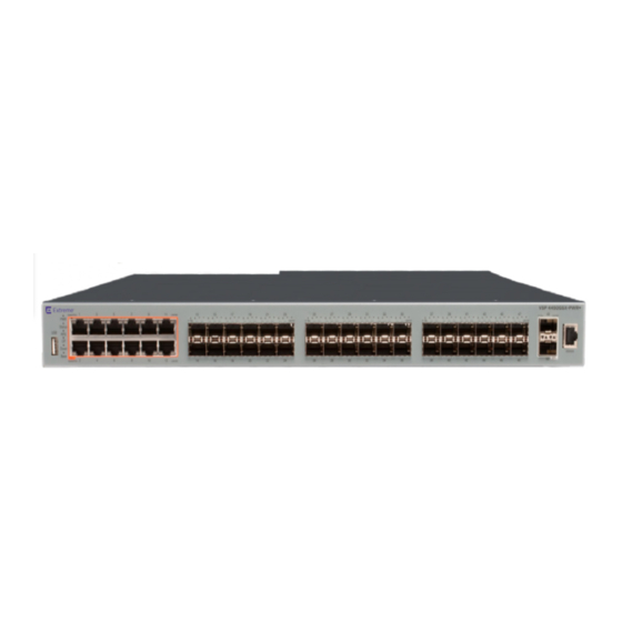
Chapter 5: Installing the VSP 4450GSX- PWR+ series Installation checklist Use this checklist to install the VSP 4450GSX-PWR+and VSP 4450GSX-DC. Task Description Install the VSP 4450GSX series. You can install the switch in two ways: • Installing the Virtual Services Platform 4000 on a table or shelf on page 22 •... - Page 17 Installation fundamentals 1. 12 10/100/1000 Mbps RJ45 ports with PoE+ 2. 36 100/1000 Mbps SFP ports 3. 2 1/10 Gbps SFP+ ports Figure 1: VSP 4450GSX-PWR+ 1. USB 2.0 port Note: The VSP 4450GSX-PWR+ model does not require a USB device in the USB port for normal operation. The USB port can be used for additional storage using USB memory stick.
-
Page 18: Electrostatic Discharge
Installing the VSP 4450GSX-PWR+ series Note: The VSP 4450GSX-DC model does not require a USB device in the USB port for normal operation. The USB port can be used for additional storage using USB memory stick. No log messages are generated when you plug or unplug the USB from the VSP 4450GSX-DC. 2. -
Page 19: Preventing Electrostatic Damage In New Cable Installations
Technical specifications Preventing electrostatic damage in new cable installations With new cable installations, you are recommended to use an ESD discharge cable to reduce the potential for damage from static, that can build up in cables. The following figure illustrates an ESD cable. -
Page 20: Environmental Requirements
Installing the VSP 4450GSX-PWR+ series Table 5: Physical specifications Specifications 4450GSX-PWR+ 4450GSX-DC Height 4.4 cm. – 1U 4.4 cm. – 1U Width 44 cm. 44 cm. Depth 43.6 cm. 43.68 cm. Weight 17.2lbs (7.80 kg) with 1 PSU 17.2lbs (7.80 kg) with 1 PSU installed. -
Page 21: Airflow Direction
Airflow direction Environmental requirement Virtual Services Platform 4000 models • Adequate clearance at the front and rear of the switch for access to cables. Warning: To avoid bodily injury from hazardous electrical shock and current, never remove the top of the device. -
Page 22: Installing The Virtual Services Platform 4000 On A Table Or Shelf
Installing the VSP 4450GSX-PWR+ series Installing the Virtual Services Platform 4000 on a table or shelf You can install a single VSP 4000 switch on any flat surface. The surface must support the combined weight of the switch and attached cables (from 15 and 20 pounds [7 to 9 kilograms]). Note: A factory-supplied 4450GSX series switch has a USB port but no USB device or cover. -
Page 23: Installing The Virtual Services Platform 4000 In An Equipment Rack
Installing the Virtual Services Platform 4000 in an equipment rack Installing the Virtual Services Platform 4000 in an equipment rack To install an VSP 4000 switch in an equipment rack, perform this procedure. Note: A factory-supplied 4450GSX series switch has a USB port but no USB device or cover. Prerequisites for installing the VSP 4000 in an equipment rack: •... -
Page 24: Cable Requirements For The Virtual Services Platform 4000
Installing the VSP 4450GSX-PWR+ series 2. Slide the switch into the rack as illustrated. 3. Insert and tighten the rack-mount screws. Cable requirements for the Virtual Services Platform 4000 The following table describes the cables required for the VSP 4000 switch. August 2018 Installing the Virtual Services Platform 4450GSX-PWR+... -
Page 25: Installation And Removal Of Small Form Factor Pluggable (Sfp) Transceivers
Installation and removal of Small Form Factor Pluggable (SFP) transceivers Table 7: Switch cable requirements Required Cable Description 10/100/1000BASE-T Ports The interconnect cabling must conform to the Cat5e, Cat6, or Cat6e specification of the Commercial Building Telecommunications Cabling Standard, ANSI/TIA/EIA 568-B fitted with an RJ45 Module jack. 10/100BASE-TX Ports The interconnect cabling for 10BASE-T Ethernet must conform to Cat3, Cat4, Cat5 (or better) UTP cabling for distances up to 100... -
Page 26: Removing Sfp Transceivers
Installing the VSP 4450GSX-PWR+ series 3. Grasp the transceiver between your thumb and forefinger. 4. Insert the transceiver into the proper module on the switch. Apply a light pressure to the transceiver until it clicks and locks into position in the module. 5. -
Page 27: Console Port Pin Assignments
Console port pin assignments Table 8: PWR+ RJ45 connector pin assignments Connector Pin Number Signal Description RX+/power– Receive Data+/power– RX–/power– Receive Data–/power– TX+/power+ Transmit Data+/power+ Not applicable Not applicable Not applicable Not applicable TX–/power+ Transmit Data–/power+ Not applicable Not applicable Not applicable Not applicable Important:... -
Page 28: Installing The Virtual Services Platform 4000 Power Supply
VSP 4000 hardware can vary. This procedure only applies to hardware models with field replaceable power supplies. Important: Extreme Networks does not support installing a combination of AC-input and DC-input power supplies in the same chassis. Procedure 1. If a blanking plate covers the required power supply slot, remove the blanking plate before attempting to insert the power supply. -
Page 29: Power Supply Power Specifications For The Vsp 4450Gsx Series Switches
Installing the Virtual Services Platform 4000 power supply Note: Do not connect an AC and DC power supply in the same chassis. Load sharing may be affected. Important: You can hot swap power supplies while the switch is operational. One power supply is required for continued switch operation. - Page 30 Installing the VSP 4450GSX-PWR+ series Figure 5: IEC 60320 C16 connector Power over Ethernet Plus (PoE+) specifications Table 11: VSP 4450GSX-PWR+ PoE+ specifications Maximum PoE+ W Average PoE+ W on 12 ports 835W with one power supply 17.8W or 32.4W (802.3.at) — 1 power supply 1835W with two power supplies •...
-
Page 31: Connect Ac Power
Connect AC power Table 13: DC power supply specifications Description DC-DC-12V-300 W Output power 300 W Input voltage 48 V DC Input current 10 A Output voltage 12 V DC Output current 25 A Mean time between failures 293,000 hours The following table describes the regulatory DC power specifications for the VSP 4450GSX-DC switch. -
Page 32: Connect Power To The Rear Panel
Installing the VSP 4450GSX-PWR+ series Country and Plug Specification Specifications Typical Plug • Harmonized cord (HAR marking on the outside of the cord jacket to comply with the CENELEC Harmonized Document HD-21) United States of America, Canada, and Japan: • 100 or 120VAC •... - Page 33 Connect AC power Figure 6: Connecting AC power to the rear panel Warning: Disconnecting the AC power cord is the only way to turn off AC power to the VSP 4000. Always connect the AC power cord in a quickly and safely accessible location in case of an emergency. For a translation of this statement, see Translations of safety messages on page 41.
- Page 34 Installing the VSP 4450GSX-PWR+ series CP1 [03/24/14 18:39:06.000] LifeCycle: INFO: Stopping all processes CP1 [03/24/14 18:39:08.000] LifeCycle: INFO: All processes have stopped CP1 [03/24/14 18:39:08.000] LifeCycle: INFO: All applications shutdown, starting power down sequence INIT: Sending processes the TERM signal Stopping OpenBSD Secure Shell server: sshdno /usr/sbin/sshd found;...
-
Page 35: Led State Definitions
LED state definitions LED state definitions The figures and tables in the following sections describe the LEDs on the Virtual Services Platform 4000 Series switches. The tables describe LED operation for a switch that finishes the power-on self-test. Front panel LEDs The following diagram illustrates the components on the front panels of the VSP 4450GSX-PWR+ switch. -
Page 36: Port Led State Indicators
Installing the VSP 4450GSX-PWR+ series Note: Indicator states are applicable to all models of VSP 4000 switches. Table 16: Switch LED state indicators Label Color and Status Description Green (solid) The switch is receiving power either from the primary or secondary power supply. - Page 37 LED state definitions • Link indicates the presence of an Ethernet link. • Speed indicates the port speed (for example, 10 Mbps, 100 Mbps, 1000 Mbps). Table 17: RJ45 Port LED state indicators Label Color and Status Description Speed/PoE+ Green, Blink The port is set to operate at 1000 Mbps with PoE.
-
Page 38: Viewing Hardware Information
: 0 day(s), 00:06:12 SysContact : http://www.extremenetworks.com/contact/ SysLocation : 9 Northeastern Blvd,Salem,NH. 03079 Chassis Info: Chassis : 4450GSX-PWR+ ModelName : 4450GSX-PWR+ BrandName : Extreme Networks. Serial# : SDNIV50S1016 H/W Revision : R0B H/W Config Part Number NumSlots NumPorts : 50 BaseMacAddr... - Page 39 Viewing hardware information Power Supply Info : Ps#1 Status : UP Ps#1 Type : AC Ps#1 Description : AC-DC-54V-1000W Ps#1 Serial Number: LBNNTMDT202R7H Ps#1 Version : -- Ps#1 Part Number : 325220-A.01 Ps#2 Status : empty Total Power Available : 1000 watts Total Power Usage : 127 watts Fan Info :...
- Page 40 Installing the VSP 4450GSX-PWR+ series Variable definitions Use data in the following table to use the show sys-info command. Variable Value card Displays information about the device. Includes type, serial number, and assembly date. Displays information about installed cooling ports. Displays LED information in detail.
-
Page 41: Chapter 6: Translations Of Safety Messages
Chapter 6: Translations of safety messages Caution: When you mount this device in a rack, do not stack units directly on top of one another. You must secure each unit to the rack with appropriate mounting brackets. Mounting brackets cannot support multiple units. Important: Achtung: Wenn diese Einheit in einem Rack montiert wird, muß... - Page 42 Translations of safety messages Caution: If you are not installing a module in the slot, be sure to keep the metal cover plate in place over the slot. Removing the cover plate impedes airflow and proper cooling of the unit. Important: Achtung: Wenn Sie kein Modul im Schacht verwenden, muß...
- Page 43 Warning: Disconnecting the AC power cord is the only way to turn off AC power to this device. Always connect the AC power cord in a quickly and safely accessible location in case of an emergency. Important: Warnung: Das Gerät kann nur durch Ziehen des Netzsteckers ausgeschaltet werden. Schließen Sie das Netzkabel an einer Steckdose an, die in Notfällen schnell und sicher zugänglich ist.
- Page 44 L'assenza di un percorso per la messa a terra verso lo switch può comportare un eccesso di emissioni. Warning: The lithium battery is not field replaceable. It must only be removed and replaced by authorized personnel. Contact Extreme Networks Technical Support for assistance if the battery requires replacement. Important: Warnung: Die Lithiumbatterie kann nicht vor Ort ausgetauscht werden.
- Page 45 Important: Aviso: A bateria de lítio não é substituível em campo. Só deve ser removida e substituída por pessoal autorizado. Entre em contato com o Suporte Técnico da Extreme Networks para obter assistência, se a bateria precisar de substituição. Important: Предупреждение:...
Need help?
Do you have a question about the ExtremeSwitching Virtual Services Platform 4450GSX-PWR+ and is the answer not in the manual?
Questions and answers