Table of Contents
Advertisement
Quick Links
Advertisement
Table of Contents

Related Manuals for Extreme Networks ExtremeSwitching Virtual Services Platform 4850GTS Series


Summary of Contents for Extreme Networks ExtremeSwitching Virtual Services Platform 4850GTS Series
- Page 1 Installing Virtual Services Platform 4850GTS Series 9035363 Rev.02 August 2018...
- Page 2 Extreme Networks including the selection, arrangement and design ON BEHALF OF YOURSELF AND THE ENTITY FOR WHOM YOU of the content is owned either by Extreme Networks or its licensors ARE DOING SO (HEREINAFTER REFERRED TO and is protected by copyright and other intellectual property laws INTERCHANGEABLY AS “YOU”...
- Page 3 VIDEO IN COMPLIANCE WITH THE AVC STANDARD (“AVC consent of Extreme Networks can be a criminal, as well as a civil VIDEO”) AND/OR (II) DECODE AVC VIDEO THAT WAS ENCODED offense under the applicable law.
-
Page 4: Table Of Contents
Training ...................... 6 Providing Feedback to Us .......................... 6 Getting Help .................... 7 Extreme Networks Documentation .................. 7 Subscribing to Service Notifications Chapter 2: New in this document.................... 9 Chapter 3: Hardware models for VSP 4850GTS Series............ 10 ...................... 11 VSP 4000 power supplies .................. - Page 5 Contents .................. 34 Connect power to the rear panel ...................... 36 LED state definitions ...................... 36 Front panel LEDs .................... 38 Switch LED state indicators .................... 39 Port LED state indicators .................... 40 Viewing hardware information Chapter 6: Translations of safety messages................ 43 August 2018 Installing Virtual Services Platform 4850GTS Series...
-
Page 6: Chapter 1: Preface
• Ideas for improvements to our documentation so you can find the information you need faster. • Broken links or usability issues. If you would like to provide feedback to the Extreme Networks Information Development team about this document, please contact us using our short online feedback form. -
Page 7: Extreme Networks Documentation
– A forum for Extreme customers to connect with one another, get questions answered, share ideas and feedback, and get problems solved. This community is monitored by Extreme Networks employees, but is not intended to replace specific guidance from GTAC. •... - Page 8 Preface About this task You can modify your product selections at any time. Procedure 1. In an Internet browser, go to http://www.extremenetworks.com/support/service-notification- form/ 2. Type your first and last name. 3. Type the name of your company. 4. Type your email address. 5.
-
Page 9: Chapter 2: New In This Document
Chapter 2: New in this document There are no feature-related changes for this release in Installing the Virtual Services Platform 4850GTS Series. August 2018 Installing Virtual Services Platform 4850GTS Series... -
Page 10: Chapter 3: Hardware Models For Vsp 4850Gts Series
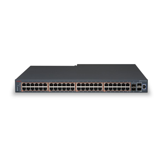
Chapter 3: Hardware models for VSP 4850GTS Series The following table describes the VSP 4850GTS Series hardware. Table 1: Hardware VSP 4000 model Description Part number VSP 4850GTS • 48 10/100/1000 Mbps RJ45 ports EC4800A78-E6 • 2 Combo 100/1000 Mbps ports •... -
Page 11: Vsp 4000 Power Supplies
VSP 4000 power supplies VSP 4000 power supplies The VSP 4000 supports both AC and DC power supplies. One power supply is installed in the system. You can install a redundant power supply to support additional power requirements or to provide power redundancy. -
Page 12: Important Operational Note
Hardware models for VSP 4850GTS Series Table 3: Power cords for power distribution units Order Code Length Power supply side Power source Safety Approval connector side connector 700512240 700512242 International except Japan and Taiwan Table 4: Power cords for use with C14 or C16 power supply side connector Order Code Description Region... - Page 13 Compatible transceivers Important: It is recommended to use Extreme Networks-branded SFP and SFP+ transceivers as they have been through extensive qualification and testing. Extreme Networks will not be responsible for issues related to non-Extreme Networks branded transceivers.
-
Page 14: Chapter 4: Preinstallation Checklist
Chapter 4: Preinstallation checklist Before you install the VSP 4850GTS, VSP 4850GTS-DC, and VSP 4850GTS-PWR+, make sure that you complete the tasks in the preinstallation checklist. Task Description Review the technical specification for For the physical, electrical, and environmental the switch. Make sure that the area specifications, see Technical specifications where you install the switch and where... - Page 15 Task Description Ensure that the rack is grounded to the same grounding electrode used by the power service in the area. The ground path must be permanent and must not exceed 1 Ohm of resistance from the rack to the grounding electrode.
-
Page 16: Chapter 5: Installing The Vsp 4000 4850Gts Series
Chapter 5: Installing the VSP 4000 4850GTS Series Installation checklist Use this checklist to install the VSP 4850GTS series. Task Description Install the VSP 4850GTS series. You can install the switch in two ways: • Installing the Virtual Services Platform 4000 on a table or shelf on page 23 •... - Page 17 2. Switch LEDs 3. 10/100/1000 Mbps ports (LEDs above ports) 4. Combo 100/1000 Mbps SFP slots. Supports Extreme Networks 1 Gbps SFPs and 100 Mbps low speed SFPs. 5. 1/10 Gbps SFP+ slots. Supports Extreme Networks 1 Gbps SFPs and 10 Gbps SFP+s.
-
Page 18: Converting Ers 4850 To Vsp 4000
2. Switch LEDs 3. 10/100/1000 Mbps PoE+ ports (LEDs above ports) 4. Combo 100/1000 Mbps SFP slots. Supports Extreme Networks 1G SFPs and 100 Mbps low-speed SFPs. 5. 1/10 Gbps SFP+ slots. Supports Extreme Networks 1 Gbps SFPs and 10 Gbps SFP+s. -
Page 19: Electrostatic Discharge
Electrostatic discharge USB considerations for factory supplied and converted VSP 4000 switches Warning: The USB FLASH drive on all models of VSP 4850 (factory built and converted from ERS 4850) must be treated as a permanent non-removable part of the switch and must NEVER be removed from the switch to ensure proper operation. -
Page 20: Preventing Electrostatic Damage In New Cable Installations
Installing the VSP 4000 4850GTS Series • Avoid contact between equipment and clothing. The wrist or ankle strap protects only the equipment from ESD voltages on the body; ESD voltages on clothing can still cause damage. • Avoid touching any connector pins. •... -
Page 21: Environmental Requirements
Environmental requirements Warning: To avoid bodily injury from hazardous electrical shock and current, never remove the top of the device. No user-serviceable components are inside. Table 5: Physical specifications Specifications 4850GTS 4850GTS-DC 4850GTS-PWR+ Height 4.4 cm. – 1RU 4.4 cm. – 1RU 4.4 cm. -
Page 22: Airflow Direction
Installing the VSP 4000 4850GTS Series Environmental requirement Virtual Services Platform 4000 models • An adequate power source is within 6 feet (1.83 meters) of the switch. One 15-amp circuit is required for each power supply. • At least 2 inches (5.08 centimeters) of clearance on each side of the switch unit for ventilation. -
Page 23: Installing The Virtual Services Platform 4000 On A Table Or Shelf
Installing the Virtual Services Platform 4000 on a table or shelf Note: Cable trays can be provided as an option. Note: Power cords must be ordered separately. Ensure you order the correct power code for your region. For more information, see Power cord types and order codes on page 11. -
Page 24: Installing The Virtual Services Platform 4000 In An Equipment Rack
Installing the VSP 4000 4850GTS Series 3. Set the switch on a table or shelf as illustrated below. Allow at least 2 inches (5.1 centimeters) on each side for proper ventilation and at least 5 inches (12.7 centimeters) at the back for power cord clearance. Installing the Virtual Services Platform 4000 in an equipment rack To install an VSP 4000 switch in an equipment rack, perform this procedure. - Page 25 Installing the Virtual Services Platform 4000 in an equipment rack Prerequisites for installing the Virtual Services Platform 4000 in an equipment rack: • Ensure that you have a space of 1.75 inches (4.45 centimeters) in height for each switch in an EIA or IEC-standard 19-inch (48.2-centimeter) equipment rack.
-
Page 26: Cable Requirements For The Virtual Services Platform 4000
Installing the VSP 4000 4850GTS Series 4. Insert and tighten the rack-mount screws. Cable requirements for the Virtual Services Platform 4000 The following table describes the cables required for the VSP 4000 switch. Table 7: Switch cable requirements Required Cable Description 10/100/1000BASE-T Ports The interconnect cabling must conform to the Cat5e, Cat6, or Cat6e... -
Page 27: Installation And Removal Of Small Form Factor Pluggable (Sfp) Transceivers
Installation and removal of Small Form Factor Pluggable (SFP) transceivers Required Cable Description Note: 100BASE-FX Transceivers are supported in SFP ports only, and not in SFP+ ports. Console Port Varies depending on the user device. The VSP 4000 has an RJ45 female connector, so a serial cable with RJ45 connectors, or a serial cable with a DB-9 female connector on one end and an RJ45 on the other is appropriate. -
Page 28: Rj45 Connector Pin Assignments
Installing the VSP 4000 4850GTS Series 3. Slide the transceiver from the module slot. 4. If the transceiver does not slide easily from the module slot, use a gentle side-to-side rocking motion while firmly pulling the transceiver from the slot. 5. -
Page 29: Console Port Pin Assignments
Console port pin assignments Important: The VSP 4000 PWR+ models use pins 1, 2, 3, and 6 for PoE+, and is compliant with Type 2 (MDI-X) in IEEE802.3at. Console port pin assignments The following table describes the console port pin assignments in the VSP 4000. Important: VSP 4000 supports only CLI Quickstart use on the console port. -
Page 30: Installing The Virtual Services Platform 4000 Power Supply
VSP 4000 hardware can vary. This procedure only applies to hardware models with field replaceable power supplies. Important: Extreme Networks does not support installing a combination of AC-input and DC-input power supplies in the same chassis. Procedure 1. If a blanking plate covers the required power supply slot, remove the blanking plate before attempting to insert the power supply. -
Page 31: Vsp 4000 Power Supply Power Specification
Installing the Virtual Services Platform 4000 power supply VSP 4000 power supply power specification The VSP 4000 supports two external field-replaceable power supplies. One power supply ships with the chassis. You can install a secondary power supply to provide redundancy and load sharing, and to add Power over Ethernet Plus (PoE+) power budget on PWR+ models. - Page 32 Installing the VSP 4000 4850GTS Series Power over Ethernet Plus specifications Table 11: VSP 4850GTS and 4850GTS-PWR+ models Maximum PoE+ W Average PoE+ W on 50 port model 855 W with one power supply 15.4 W (802.3af) 1855 W with two power supplies 17.8 W (802.3.at) —...
-
Page 33: Connect Ac Power
Connect AC power Table 14: DC power supply specifications Specifications 4850GTS-DC Output power 300 W Input voltage 48 V DC Input current 10 A Output voltage 12 V DC Output current 25 A Connect AC power This section explains power cord specifications and how to connect AC power. Power cord specifications To connect AC power to the switch, you need an appropriate AC power cord as described in the following table, also see the following table for plug specifications. -
Page 34: Connect Power To The Rear Panel
Installing the VSP 4000 4850GTS Series Danger: Using power cords with a proper grounding path Use only power cords that have a grounding path. Without a proper ground, a person who touches the switch is in danger of receiving an electrical shock. Lack of a grounding path to the switch can result in excessive emissions. - Page 35 Connect AC power Caution: Before you unplug the AC power cord, always perform the following shutdown procedure. This procedure flushes any pending data to ensure data integrity. 1. Enter the Privileged EXEC command mode: enable 2. Shutdown the VSP 4000: sys shutdown 3.
-
Page 36: Led State Definitions
Installing the VSP 4000 4850GTS Series Stopping syslogd/klogd: no syslogd found; none killed Sending all processes the TERM signal... Sending all processes the KILL signal... hwclock: can't open '/dev/misc/rtc': No such file or directory /etc/rc0.d/S25save-rtc.sh: line 5: /etc/timestamp: Read-only file system Unmounting remote filesystems... - Page 37 2. Switch LEDs 3. 10/100/1000 Mbps PoE+ ports (LEDs above ports) 4. Combo 100/1000 Mbps SFP slots. Supports Extreme Networks 1 Gbps SFPs and 100 Mbps low speed SFPs. 5. 1/10 Gbps slots. Supports Extreme Networks 1 Gbps SFPs and 10 Gbps SFP+s.
-
Page 38: Switch Led State Indicators
Installing the VSP 4000 4850GTS Series Related links LED state definitions on page 36 Switch LED state indicators The following table describes the main switch LED state indications provided by LED color and fluctuation cues. Note: Indicator states are applicable to all models of VSP 4000 switches. Table 16: Switch LED state indicators Label Color and Status... -
Page 39: Port Led State Indicators
LED state definitions Related links LED state definitions on page 36 Port LED state indicators This section describes the port LED state indicators by color and fluctuation cues. Note: Indicator states are applicable to all models of VSP 4000 switches. The following list describes the three port LEDs: •... -
Page 40: Viewing Hardware Information
Installing the VSP 4000 4850GTS Series Label Color and Status Description Amber, Steady SFP Installed—TX Port Inactive No SFP transceiver is present. Link / Activity Green, Blink Activity exists on the port. Green, Slow Blink Software disabled this port. Green, Steady The link is operating normally. - Page 41 : 0 day(s), 00:04:19 SysContact : http://www.extremenetworks.com/contact/ SysLocation : 9 Northeastern Blvd,Salem,NH. 03079 Chassis Info: Chassis : 4850GTS-PWR+ ModelName : 4850GTS-PWR+ BrandName : Extreme Networks. Serial# : 12JP442H70GH H/W Revision : 10 H/W Config : none Part Number : AL4800A88-E6 NumSlots NumPorts...
- Page 42 Installing the VSP 4000 4850GTS Series LED#5 Label : Down LED#5 Status : UnSupported LED#6 Label : Base LED#6 Status : UnSupported USB Info : Vendor Id : 196d Manufacturer : InnoDisk Product Id : 0201 Product Name : Nano : 02.50 Serial Number : 000000000077 Max Current...
-
Page 43: Chapter 6: Translations Of Safety Messages
Chapter 6: Translations of safety messages Caution: When you mount this device in a rack, do not stack units directly on top of one another. You must secure each unit to the rack with appropriate mounting brackets. Mounting brackets cannot support multiple units. Important: Achtung: Wenn diese Einheit in einem Rack montiert wird, muß... - Page 44 Translations of safety messages Caution: If you are not installing a module in the slot, be sure to keep the metal cover plate in place over the slot. Removing the cover plate impedes airflow and proper cooling of the unit. Important: Achtung: Wenn Sie kein Modul im Schacht verwenden, muß...
- Page 45 Warning: Disconnecting the AC power cord is the only way to turn off AC power to this device. Always connect the AC power cord in a quickly and safely accessible location in case of an emergency. Important: Warnung: Das Gerät kann nur durch Ziehen des Netzsteckers ausgeschaltet werden. Schließen Sie das Netzkabel an einer Steckdose an, die in Notfällen schnell und sicher zugänglich ist.
- Page 46 L'assenza di un percorso per la messa a terra verso lo switch può comportare un eccesso di emissioni. Warning: The lithium battery is not field replaceable. It must only be removed and replaced by authorized personnel. Contact Extreme Networks Technical Support for assistance if the battery requires replacement. Important: Warnung: Die Lithiumbatterie kann nicht vor Ort ausgetauscht werden.
- Page 47 Important: Aviso: A bateria de lítio não é substituível em campo. Só deve ser removida e substituída por pessoal autorizado. Entre em contato com o Suporte Técnico da Extreme Networks para obter assistência, se a bateria precisar de substituição. Important: Предупреждение:...
Need help?
Do you have a question about the ExtremeSwitching Virtual Services Platform 4850GTS Series and is the answer not in the manual?
Questions and answers