Table of Contents
Advertisement
Quick Links
Advertisement
Table of Contents

Related Manuals for HT QUICKLAN6050N


Summary of Contents for HT QUICKLAN6050N
- Page 1 ENGLISH User manual Copyright HT ITALIA 2017 Release EN 2.00 - 20/06/2017...
-
Page 2: Table Of Contents
QUICKLAN 6050N Table of contents: PRECAUTIONS AND SAFETY MEASURES ............... 2 1.1. Preliminary instructions ......................2 1.2. During use ..........................2 1.3. After use ..........................2 GENERAL DESCRIPTION ................... 3 PREPARATION FOR USE ................... 3 ... -
Page 3: Precautions And Safety Measures
QUICKLAN 6050N 1. PRECAUTIONS AND SAFETY MEASURES The instrument has been designed in compliance with the safety directives relevant to electronic measuring instruments. For your safety and in order to prevent damaging the instrument, please carefully follow the procedures described in this manual and read all notes preceded by symbol with the utmost attention. -
Page 4: General Description
QUICKLAN 6050N 2. GENERAL DESCRIPTION Model QUICKLAN6050N allows carrying out tests on LAN network cable wirings, telephone cables and coaxial cables. The instrument has the following features: Test of wiring errors on LAN network cables with RJ45 connector in CAT5 and CAT6. -
Page 5: Nomenclature
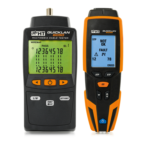
QUICKLAN 6050N 4. NOMENCLATURE 4.1. DESCRIPTION OF THE INSTRUMENT CAPTION: 1. Section input connectors 2. LCD display 3. Arrow keys 4. ON/OFF key 5. L/W key 6. SET/UNIT key 7. TEST/ 8. RJ11 connector 9. F connector 10. RJ45 connector 11. -
Page 6: Description Of Function Keys
QUICKLAN 6050N 4.3. DESCRIPTION OF FUNCTION KEYS 4.3.1. ON/OFF key Press the key to switch on or off the instrument. The LCD display shows all of its segments for a moment. The key is also used to set the instrument s parameters (see §... -
Page 7: Operating Instructions
QUICKLAN 6050N 5. OPERATING INSTRUCTIONS 5.1. INSTRUMENT SETTINGS 5.1.1. Auto Power OFF function 1. Switch on the instrument by pressing the key. 2. Press and hold the SET/UNIT key for 3s. The screen in Fig. 3 left side appears on the –... -
Page 8: Setting The Cable Type
QUICKLAN 6050N 5.1.3. Setting the cable type 1. Switch on the instrument by pressing the key. 2. Press and hold the SET/UNIT key for 3s. The screen in Fig. 3 left side appears on – the display. 3. Press the arrow keys until you display the screen in Fig. -
Page 9: Test Of Cable Mapping With Rj45 Connector
QUICKLAN 6050N 5.2. TEST OF CABLE MAPPING WITH RJ45 CONNECTOR The test allows checking the cable mapping of LAN networks, in CAT5 or CAT6, of type UTP or STP with RJ45 connector, detecting possible wiring errors. Proceed as follows: 1. Switch on the instrument by pressing the key. 2. -
Page 10: Mapping Test Results
QUICKLAN 6050N 5.2.1. Mapping test results Situation Description Display Correctly performed test on Message UTP cable connected to PASS on the display “ ” remote unit #1 Correctly performed test on Message STP cable connected to PASS on the display “... - Page 11 QUICKLAN 6050N Symbol on the display Cables of pair 3-6 inverted INVERTED PAIR Symbol on the display Cables of pair 3-6 crossed with cables of pair 4-5 CROSSED PAIRS Cables pair inverted Symbol on the display Cable 4 of the pair 4-5 short-circuited with GENERIC ERROR...
-
Page 12: Description Of Errors Of Split Pairs
QUICKLAN 6050N 5.2.2. Description of errors of split pairs Inside the network cables, the eight conductors are twisted two by two, thus forming four pairs: 1-2, 3-6, 4-5, 7-8 and this guarantees the performance declared by the manufacturer. The error condition SPLIT PAIRS is given by the exchange of two conductors belonging to different pairs, found in both positions of the cable to be tested (see Fig. -
Page 13: Test Of Cable Mapping With Rj11 Connector
QUICKLAN 6050N 5.3. TEST OF CABLE MAPPING WITH RJ11 CONNECTOR 1. Switch on the instrument by pressing the key. 2. Select the type of cable AJII (RJ11) to be tested (see § 5.1.3). 3. Connect the ends of the cable to be tested to the instrument s input RJ11 connector ’... -
Page 14: Test Of Coax Cable Mapping With F Connector
QUICKLAN 6050N 5.4. TEST OF COAX CABLE MAPPING WITH F CONNECTOR 1. Switch on the instrument by pressing the key. 2. Select the type of cable COA (COAX) to be tested (see § 5.1.3). 3. Connect the ends of the cable to be tested to the instrument s input COAX connector ’... -
Page 15: Measurement Of Cable Length
QUICKLAN 6050N 5.5. MEASUREMENT OF CABLE LENGTH The instrument measures the length of cables with RJ45 connectors of type UTP/STP, on RJ11 cables and on coaxial cables (COAX) with F connector. Proceed as follows: 1. Switch on the instrument by pressing the key. 2. - Page 16 QUICKLAN 6050N 3. The numeric marker (default) flashes on the display. Press the arrow key “ ” to select the value among the options 0 ÷ 9. This numeric marker is associated to the one considered when setting the type of cable (see § 5.1.3). 4.
-
Page 17: Maintenance
QUICKLAN 6050N 6. MAINTENANCE 6.1. GENERAL INFORMATION 1. While using and storing the instrument, carefully observe the recommendations listed in this manual in order to prevent possible damage or danger during use. 2. Do not use the instrument in environments with high humidity levels or high temperatures. -
Page 18: Technical Specifications
QUICKLAN 6050N 7. TECHNICAL SPECIFICATIONS 7.1. TECHNICAL CHARACTERISTICS Input connectors RJ45, RJ11, COAX (F) Cable type RJ45: UTP, STP Category: CAT5, CAT6 Considered standard: TIA/EIA 568B Detected wiring errors: open pairs, short-circuited pairs, inverted pairs, crossed pairs slit pairs, generic errors Max operating altitude: 2000m (6562ft) Length range (1):... -
Page 19: Service
QUICKLAN 6050N 8. SERVICE 8.1. WARRANTY CONDITIONS This instrument is warranted for 1 year against any material or manufacturing defect, in compliance with the general sales conditions. During the warranty period, defective parts may be replaced. However, the manufacturer reserves the right to repair or replace the product.
Need help?
Do you have a question about the QUICKLAN6050N and is the answer not in the manual?
Questions and answers