Table of Contents
Advertisement
Advertisement
Table of Contents

Related Manuals for HT HT7


Summary of Contents for HT HT7
- Page 1 ENGLISH User manual Copyright HT ITALIA 2014 Release EN 1.05 - 21/03/2019...
-
Page 2: Table Of Contents
Table of content : SAFETY PRECAUTIONS AND PROCEDURES ............2 1.1. Preliminary ........................2 1.2. During use ........................3 1.3. After use .......................... 3 1.4. Overvoltage categories - definitions ................. 3 GENERAL DESCRIPTION ................... 4 PREPARATION FOR USE ................... 4 3.1. -
Page 3: Safety Precautions And Procedures
1. SAFETY PRECAUTIONS AND PROCEDURES This instrument complies with IEC/EN61010-1 relative to electronic measuring instruments. For your own safety and to avoid damaging the instrument follow the procedures described in this instruction manual and read carefully all notes preceded by this symbol When taking measurements: ... -
Page 4: During Use
1.2. DURING USE Read the recommendations which follow and the instructions in this manual: CAUTION An improper use may damage the instrument and/or its components or injure the operator. When the instrument is connected to circuits never touch an unused terminal. ... -
Page 5: General Description
2. GENERAL DESCRIPTION HT7 performs the following measurements: DC voltage with 2-wire method AC voltage with 2-wire method AC voltage with 1-wire method (polarity detection) Phase sequence indication Continuity test with buzzer Voltage measurement with low impedance input The measure is displayed with indication of measurement unit both in numerical mode and as bargraph. -
Page 6: Operating Instructions
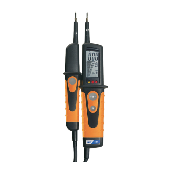
10. Battery cover 11. Low impedance switch (L1) Fig. 1: Instrument description 4.2. DESCRIPTION OF SYMBOLS AT DISPLAY The following symbols can be displayed on HT7: Symbol Description DC voltage measurement AC voltage measurement Negative polarity on DC voltage measurement... -
Page 7: Dc Voltage Measurement
4.4. DC VOLTAGE MEASUREMENT CAUTION The maximum input for DC voltage is 690V. Do not measure higher voltages to avoid risks of electrical shocks or serious damages to the instrument. symbol is lighted up whenever the voltage between the probes ... -
Page 8: Ac Voltage Measurement
4.5. AC VOLTAGE MEASUREMENT CAUTION The maximum input for AC voltage is 690V. Do not measure higher voltages to avoid risks of electrical shocks or serious damages to the instrument. symbol is lighted up whenever the voltage between the probes ... -
Page 9: Ac Voltage Measurement With Low Input Impedance
4.6. AC VOLTAGE MEASUREMENT WITH LOW INPUT IMPEDANCE CAUTION The maximum input for AC voltage is 690V. Do not measure higher voltages to avoid risks of electrical shocks or serious damages to the instrument. symbol is lighted up whenever the voltage between the probes ... -
Page 10: 1-Wire Ac Voltage Detection (Polarity)
4.7. 1-WIRE AC VOLTAGE DETECTION (POLARITY) CAUTION The maximum input for AC voltage is 690V. Do not measure higher voltages to avoid risks of electrical shocks or serious damages to the instrument. The 1-wire AC voltage mode should be used as a quick voltage detection test with no voltage value displaying. -
Page 11: Phase Sequence Indication
4.8. PHASE SEQUENCE INDICATION CAUTION The maximum input for AC voltage is 690V. Do not measure higher voltages to avoid risks of electrical shocks or serious damages to the instrument. symbol is lighted up whenever the voltage between the probes exceeds 50V, even if the batteries are low or have been removed. -
Page 12: Continuity Test
4.9. CONTINUITY TEST CAUTION Before taking the continuity test, disconnect the circuit under test from any power source and discharge all capacitors. 1. Perform the preliminary Autotest (see § 4.3). 2. Connect the L1 and L2 probes to the object under test (see Fig. -
Page 13: Maintenance
5. MAINTENANCE 5.1. GENERAL INFORMATION This instrument is a precision device. Whether in use or in storage, please do not exceed the specification requirements to avoid possible damages or dangers. Do not place this instrument at high temperatures or humidity, or expose it to direct sunlight. Be sure to turn off the instrument after use. -
Page 14: Technical Specifications
6. TECHNICAL SPECIFICATIONS 6.1. TECHNICAL CHARACTERISTICS Accuracy is indicated as [%reading + (no. of digits) * resolution] at 23°C±5°C, <70%RH AC/DC Voltage Range Resolution Accuracy Input impedance Overload protection (1.0rdg+3dgt) (DC voltage) 6, 12, 24, 50, 120, 690VAC/DC 1M 230, 400, 690V (1.5rdg+5dgt) (AC voltage) -
Page 15: General Specifications
6.1.3. General specifications Mechanical characteristics Dimensions (L x W x H): 240 x 78 x 40mm (9.4 x 3.1 x 1.6in) Weight (including batteries): 240g (7.7ounces) Power supply Battery type: 2x1.5V batteries type AAA LR03 Indication of low batteries: " "is displayed Auto power off / on fixed... -
Page 16: Service
7. SERVICE 7.1. WARRANTY CONDITIONS This instrument is guaranteed for one year against material or production defects, in accordance with our general sales conditions. During the warranty period the manufacturer reserves the right to decide either to repair or replace the product. Should you need for any reason to return back the instrument for repair or replacement take prior agreements with the local distributor from whom you bought it.
Need help?
Do you have a question about the HT7 and is the answer not in the manual?
Questions and answers