Table of Contents
Advertisement
Quick Links
Advertisement
Table of Contents

Related Manuals for HT EASYTEST COMBI519


Summary of Contents for HT EASYTEST COMBI519
- Page 1 Copyright HT ITALIA 2021 Release EN 1.00 - 26/04/2021...
-
Page 2: Table Of Contents
EASYTEST-COMBI519 TABLE OF CONTENTS PRECAUTIONS AND SAFETY MEASURES ............... 4 1.1. Preliminary instructions ..................... 4 1.2. During use ......................... 5 1.3. After use ..........................5 1.4. Definition of measurement (overvoltage) category ............5 GENERAL DESCRIPTION ................... 6 ... - Page 3 EASYTEST-COMBI519 6.7.9. Verification of protection against indirect contacts (TT systems) .......... 69 6.7.10. Verification of protection against indirect contacts (TN systems) .......... 71 6.7.11. Anomalous situations ......................73 6.8. LoZ: Line/Loop impedance with high resolution .............. 76 6.9. ...
-
Page 4: Precautions And Safety Measures
EASYTEST-COMBI519 1. PRECAUTIONS AND SAFETY MEASURES The instrument has been designed in compliance with guidelines IEC/EN61557, BS7671 17th and 18th editions and IEC/EN61010, relevant to electronic measuring instruments. Before and after carrying out the measurements, carefully observe the following instructions: ... -
Page 5: During Use
EASYTEST-COMBI519 1.2. DURING USE Please carefully read the following recommendations and instructions: CAUTION Failure to comply with the caution notes and/or instructions may damage the instrument and/or its components or be a source of danger for the operator. Before changing function, disconnect the test leads from the circuit under test. ... -
Page 6: General Description
EASYTEST-COMBI519 2. GENERAL DESCRIPTION 2.1. FOREWORD This user manual is referred to the following models EASYTEST and COMBI521. Unless otherwise specified, the “instrument” is referred to COMBI519 model. The following Table 1 shows the possible functions Name Mesurement description EASYTEST COMBI519 AUTO sequence of Ra , RCD, M... -
Page 7: Instrument Functions
EASYTEST-COMBI519 2.2. INSTRUMENT FUNCTIONS The instrument can perform the following tests: RPE Continuity test of earth, protective and equipotential conductors with test current higher than 200mA and open-circuit voltage between 4V and 24V. M Measurement of insulation resistance with continuous test voltage of 50V, 100V, 250V, 500V or 1000V DC. -
Page 8: Preparation For Use
EASYTEST-COMBI519 3. PREPARATION FOR USE 3.1. INITIAL CHECKS Before shipping, the instrument has been checked from an electric as well as a mechanical point of view. All possible precautions have been taken so that the instrument is delivered undamaged. However, we recommend checking it to detect any damage possibly suffered during transport. -
Page 9: Nomenclature
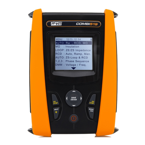
EASYTEST-COMBI519 4. NOMENCLATURE 4.1. INSTRUMENT DESCRIPTION CAPTION: 1. Inputs 2. LCD display 3. ,, , , SAVE/ENTER keys 4. Compartment connector optical cable/USB port 5. GO/STOP key 6. HELP/ 7. ESC/MENU key 8. ON/OFF key Fig. 1: Description of the front part of the instrument CAPTION: 1. -
Page 10: Keyboard Description
EASYTEST-COMBI519 4.3. KEYBOARD DESCRIPTION The keyboard includes the following keys: ON/OFF key to switch on/off the instrument ESC key to exit the selected menu without confirming MENU key to go back to the general menu at any time keys to move the cursor through the different screens in order to select the desired programming parameters SAVE/ENTER key to save the selected setup parameters (SAVE) and to select the desired function (ENTER) from the menu... -
Page 11: General Menu
EASYTEST-COMBI519 5. GENERAL MENU Pressing the MENU/ESC key in any condition of the instrument allows going back to the general menu in which internal parameters may be set and the desired measuring function may be selected. MENU MENU 15/10 – 18:04 15/10 –... -
Page 12: Country
EASYTEST-COMBI519 5.1.2. Country Move the cursor to Country by means of the arrow keys 15/10 – 18:04 S E T (,) and confirm with ENTER. Subsequently, the display E u r o p e shows the screen which allows selecting the country of E x t r a E u r o p e reference, which will influence the LOOP and Ra G e r m a n y... -
Page 13: General Settings
C O M B I 5 1 9 and confirm with ENTER. Subsequently, the display shows the initial screen as indicated in the screen to the side. HT ITALIA SN: 21010037 Press the ESC key to return to the main menu. -
Page 14: Operating Instructions
EASYTEST-COMBI519 6. OPERATING INSTRUCTIONS 6.1. AUTO: AUTOMATIC TEST SEQUENCE (RA , RCD, M) This function allows performing the following measurements in an automatic sequence: Overall earth resistance without causing the RCD’s tripping (Ra ) Tripping current and tripping time of General RCDs type A ( ), AC ( ) or B ( ... - Page 15 EASYTEST-COMBI519 TN systems Press the MENU key, move the cursor to AUTO in the 15/10 – 18:04 A U T O > < main menu by means of the arrow keys (,) and confirm with ENTER. Subsequently the instrument I s c = - - - A Z L - N = - - - Ω...
- Page 16 EASYTEST-COMBI519 Note the correct voltage values between L-N and L-PE as 15/10 – 18:04 A U T O > < shown in the screen to the side. I s c = - - - A Z L - N = - - - Ω I f c = - - - A Z L - P E = - - - Ω...
- Page 17 EASYTEST-COMBI519 The insulation test starts and the screen to the side 15/10 – 18:04 A U T O > < appears on the display. The RL-N, RL-PE and RN-PE values appear on the display. > 9 9 9 M R L - N V t = 5 2 3 V In case of a positive result of all the tests sequentially...
- Page 18 EASYTEST-COMBI519 TT/IT systems 1. Press the MENU key, move the cursor to AUTO in the 15/10 – 18:04 A U T O > < main menu by means of the arrow keys (,) and confirm with ENTER. Subsequently, the instrument R A = - - - ...
- Page 19 EASYTEST-COMBI519 CAUTION If message “Measuring…” appears on the display, the instrument is performing measurement. During this whole stage, do not disconnect the test leads of the instrument from the mains. The Ra test starts and the screen to the side appears on 15/10 –...
- Page 20 EASYTEST-COMBI519 In case of a negative result of the Ra test (see § 12.8), 15/10 – 18:04 A U T O > < the auto test is automatically blocked, the message “NOT OK” is shown and the screen to the side is displayed. R A = 1 8 2 4 ...
-
Page 21: Anomalous Situations
EASYTEST-COMBI519 6.1.1. Anomalous situations 1. If the instrument detects a L-N or L-PE voltage higher 15/10 – 18:04 A U T O than the maximum limit (265V), it does not carry out the I s c = - - - A Z L - N = - - - Ω... -
Page 22: Dmm: Digital Multimeter Function
EASYTEST-COMBI519 6.2. DMM: DIGITAL MULTIMETER FUNCTION This function allows reading the real time TRMS values of P-N Voltage, P-PE Voltage, N- PE Voltage and Frequency (@ P-N inputs) when the instrument is connected to an installation. Fig. 6: Instrument connection through mains plug Fig. - Page 23 EASYTEST-COMBI519 3. The TRMS values of L-N voltage, L-PE voltage, N-PE 15/10 – 18:04 D M M voltage and the frequency of L-N voltage are shown on the display. FREQ. = 50.00 VL-N = 230 Press the GO/STOP key to enable/disable the “HOLD” VL-PE = 230 function in order to fix the value on the display.
-
Page 24: Rpe: Continuity Of Protective Conductors
EASYTEST-COMBI519 6.3. RPE: CONTINUITY OF PROTECTIVE CONDUCTORS This function is performed in compliance with standards IEC/EN61557-4, BS7671 17th/18th edition and allows measuring the resistance of protective and equipotential conductors. CAUTION The instrument can be used for measurements on installations with overvoltage category CAT IV 300V to earth and max 415V between inputs. - Page 25 EASYTEST-COMBI519 Fig. 9: Continuity test by means of remote switch probe Press the MENU key, move the cursor to RPE in the main 15/10 – 18:04 R P E menu by means of the arrow keys (,) and confirm with - - - ...
-
Page 26: Tmr Mode
EASYTEST-COMBI519 CAUTION Always make sure, before any test, that the compensation resistance value of the cables is referred to the cables currently used. In case of doubt, repeat the cable calibration procedure as indicated in § 6.3.2. Press the GO/STOP key on the instrument or the START key on the remote switch probe. -
Page 27: Mode
EASYTEST-COMBI519 At the end of the set duration time, the instrument shows 15/10 – 18:04 R P E on the display the maximum value among all the partial 0 . 5 4 measurements performed and the message "OK" in case of a positive result (value lower than the set limit threshold) I t e s t 2 0 9 m A... -
Page 28: Anomalous Situations
EASYTEST-COMBI519 6.3.3. Anomalous situations In case the detected value is higher than the set limit, the 15/10 – 18:04 R P E instrument gives a long acoustic signal and displays a 4 . 5 4 screen similar to the one reported here to the side. I t e s t 2 1 2 m A N O T O K... -
Page 29: Lo: Continuity Of Protective Conductors With 10A
EASYTEST-COMBI519 6.4. LO: CONTINUITY OF PROTECTIVE CONDUCTORS WITH 10A This function allows measuring the resistance of protective and equipotential conductors with a test current >10A by using the Lo 10A optional accessory connected to the instrument through the C2050 cable. The optional accessory Lo 10A must be directly powered by the mains on which measurements are performed. - Page 30 EASYTEST-COMBI519 Use the , keys to select the “INFO” item. The screen L o 15/10 – 18:04 to the side is shown on the display indicating the L O W 1 0 A S N : 2 0 0 9 0 0 1 1 information relevant to the accessory.
-
Page 31: Anomalous Situations
EASYTEST-COMBI519 6.4.1. Anomalous situations If the instrument detects a voltage higher than 3V at its L o 15/10 – 18:04 terminals, it does not perform the test, it emits a prolonged - - - acoustic signal and displays a screen like the one to the side. -
Page 32: M: Measurement Of Insulation Resistance
EASYTEST-COMBI519 6.5. M: MEASUREMENT OF INSULATION RESISTANCE This function is performed in compliance with standards IEC/EN61557-2, BS7671 17th/18th edition and allows measuring the insulation resistance between the active conductors and between each active conductor and the earth. The following operating modes are available: ... - Page 33 EASYTEST-COMBI519 Fig. 13: Insulation between L-N-PE by means of mains plug (MAN and AUTO) Fig. 14: Insulation between L-PE by means of mains plug (TMR mode) Fig. 15: Insulation between L-PE by means of single cables (TMR mode) EN - 33...
- Page 34 EASYTEST-COMBI519 Fig. 16: Insulation between L-PE by means of single cables and remote switch probe (TMR mode)) Press the MENU key, move the cursor to M in the main M 15/10 – 18:04 menu by means of the arrow keys (,) and confirm with - - - M ...
- Page 35 EASYTEST-COMBI519 CAUTION Disconnect any cable not strictly involved in measurement. Before connecting the test leads, make sure that there is no voltage at the ends of the conductors to be tested. 5. Connect the test leads and remote switch probe to the ends of the conductors to be tested as shown in Fig.
-
Page 36: Tmr Mode
EASYTEST-COMBI519 6.5.1. TMR mode With the arrow keys (,) select the "TMR" option in the M 15/10 – 18:04 "Mode" section. The instrument displays a screen like the - - - M one shown to the side. Set the duration of the Vt = - - - V T = - - - s measurement in the "Time"... -
Page 37: Auto Mode
EASYTEST-COMBI519 6.5.2. AUTO mode With the arrow keys (,) select the "AUTO" option in M 15/10 – 18:04 the "Mode" section. The instrument displays a screen like - - - M Vt = - - - V RL-N the one shown to the side. Set the duration of the RL-PE - - - M... -
Page 38: Anomalous Situations
EASYTEST-COMBI519 6.5.3. Anomalous situations If the instrument fails to generate the nominal voltage, it M 15/10 – 18:04 emits a long acoustic signal to indicate the negative result 0 . 0 1 M of the test and displays a screen like the one at the side. NOT OK 500V 1.00M... - Page 39 EASYTEST-COMBI519 If the instrument detects a voltage higher than 10V at its M 15/10 – 18:04 terminals, it does not perform the test, emits a prolonged - - - M acoustic signal and displays a screen like the one at the side.
-
Page 40: Rcd: Test On Differential Switches
EASYTEST-COMBI519 6.6. RCD: TEST ON DIFFERENTIAL SWITCHES This function is performed in compliance with standard IEC/EN61557-6, BS7671 17th/18th edition and allows measuring the tripping time and current of molded-case differential switches of type A ( ) , AC ( ) or B ( ) being General (G) and Selective (S). - Page 41 EASYTEST-COMBI519 Fig. 17: Connection for single-phase 230V system by means of mains plug Fig. 18: Connection for single-phase 230V system with single cables and remote switch probe Fig. 19: Connection for 400V + N + PE three-phase system by means of single cables and remote switch probe EN - 41...
- Page 42 EASYTEST-COMBI519 Fig. 20: Connection for a 400V + N (no PE) three-phase system by means of single cables and remote switch probe Fig. 21: Connection for a 400V + PE (no N) system with cables and remote switch probe Press the MENU key, move the cursor to RCD in the R C D 15/10 –...
-
Page 43: Auto Mode
EASYTEST-COMBI519 3. Insert the green, blue and black connectors of the three-pin plug cable into the corresponding inputs B3, B4 and B1 of the instrument. As an alternative, use the single cables and apply the relevant alligator clips to the free ends of the cables. It is also possible to use the remote switch probe by inserting its multipolar connector into the input B1. -
Page 44: Auto Mode
EASYTEST-COMBI519 7. In case of a positive result (all tripping times comply 15/10 – 18:04 R C D with what indicated in 12.4) of all the test sequentially 0 ° 1 8 0 ° performed, the “OK” message is shown and the screen 3 8 m s 3 5 m s to the side is displayed by the instrument. -
Page 45: X1, X5 Modes
EASYTEST-COMBI519 7. In case of a positive result (all tripping times comply 15/10 – 18:04 R C D with what indicated in 12.4) of all the tests sequentially 0 ° 1 8 0 ° performed, the “OK” message is shown and the screen to the side is displayed by the instrument. -
Page 46: Mode
EASYTEST-COMBI519 6.6.4. mode The standard defines the tripping times for RCDs at nominal current. The mode is used to detect the tripping time at tripping current (which could also be lower than the nominal current). Press the GO/STOP key on the instrument, the START R C D 15/10 –... -
Page 47: Anomalous Situations
EASYTEST-COMBI519 6.6.5. Anomalous situations If the instrument detects a frequency higher than the R C D 15/10 – 18:04 maximum limit (63Hz), it does not carry out the test and - - - displays a screen like the one to the side. - - - FREQ. - Page 48 EASYTEST-COMBI519 If the instrument detects that the phase L and neutral N R C D 15/10 – 18:04 leads are inverted, it does not carry out the test and a - - - screen similar to the one reported to the side is displayed. Rotate the mains plug or check the connection of - - - measuring cables.
- Page 49 EASYTEST-COMBI519 If the instrument detects the absence of the signal to R C D 15/10 – 18:04 terminal B1 (phase conductor), it provides the warning - - - screen shown to the side and blocks the execution of the tests. - - - FREQ.
-
Page 50: Loop: Line/Loop Impedance And Overall Earth Resistance
EASYTEST-COMBI519 6.7. LOOP: LINE/LOOP IMPEDANCE AND OVERALL EARTH RESISTANCE This function is performed in compliance with standard IEC/EN61557-3, BS7671 17th/18th edition and allows measuring the line impedance, the fault loop impedance and the prospective short-circuit current. CAUTION Depending on the selected electrical system (TT, TN or IT), some connections and function modes are disabled by the instruments (see Table 2: Conditions of positive outcome depending on the test parameters). - Page 51 EASYTEST-COMBI519 Fig. 23: P-N/P-PE test for single-phase/two-phase systems with cables and remote probe Fig. 24: P-N/P-PE test for 400V+N+PE three-phase with single cables and remote probe Fig. 25: P-P measurement for 400V+N+PE three-phase systems Fig. 26: P-PE/P-N test for 400V + PE systems by means of single cables and remote probe EN - 51...
- Page 52 EASYTEST-COMBI519 Fig. 27: P-PE measurement for IT systems by means of single cables and remote probe Fig. 28: P-PE 2-wire test for single-phase/two-phase 230V systems with mains plug Fig. 29: P-PE 2-wire test for single-phase/two-phase systems with cables and remote probe Fig.
-
Page 53: Test Types
EASYTEST-COMBI519 6.7.1. Test types The protection of electrical lines is the essential part of a project to guarantee correct functionality and avoid injury to persons or damage of property. To this purpose, the safety guidelines impose on electrical designers to also design the electrical installation in order to obtain: 1. - Page 54 EASYTEST-COMBI519 Mode Condition x OK outcome Condition x OK outcome Condition x OK outcome No outcome No outcome No outcome Br.Cap Isc L-L max < BC Isc L-L max < BC Isc L-L max < BC (IscL-Lmin 2F) Tmax Tmax < TripT (IscL-Lmin 2P) Tmax ...
-
Page 55: Test Cable Calibration (Zeroloop)
EASYTEST-COMBI519 6.7.2. Test cable calibration (ZEROLOOP) In order to obtain better results, it is strongly recommended to perform the preliminary calibration of the test cables or of the cable with mains plug by using the ZEROLOOP accessory before performing the test. In this way, the instrument automatically subtracts the resistance of the test cables, providing the actual result on the display. - Page 56 EASYTEST-COMBI519 The value of the test leads/mains plug resistance is L O O P 15/10 – 18:04 maintained by the instrument up to the reset operation - - - performed by the user (for example, for the insertion of - - - ...
-
Page 57: Std Mode - Generic Test
EASYTEST-COMBI519 6.7.3. STD Mode – Generic test This mode performs the impedance measurement and the calculation of prospective short- circuit current without any evaluation. Therefore, at the end of the test, no outcome is given by the instrument. Press the MENU key, move the cursor to LOOP in the L O O P 15/10 –... - Page 58 EASYTEST-COMBI519 Press the GO/STOP key on the instrument, the START L O O P 15/10 – 18:04 key on the remote switch probe or use the AutoStart Ipfc - - - feature (see § 5.1.5). The instrument starts the measurement and the “Measuring…” message is shown ...
-
Page 59: Br.cap Mode - Verification Of The Breaking Capacity Of Protection Devices
EASYTEST-COMBI519 6.7.4. Br.Cap mode – Verification of the breaking capacity of protection devices Press the MENU key, move the cursor to LOOP in the L O O P 15/10 – 18:04 main menu by means of the arrow keys (,) and - - - confirm with ENTER. - Page 60 EASYTEST-COMBI519 Press the GO/STOP key on the instrument, the START L O O P 15/10 – 18:04 key on the remote switch probe or use the AutoStart - - - feature (see § 5.1.5). The instrument starts the measurement and the “Measuring…” message is shown ...
-
Page 61: Tript - Verification Of Protection Coordination
EASYTEST-COMBI519 6.7.5. TripT - Verification of protection coordination Press the MENU key, move the cursor to LOOP in the L O O P 15/10 – 18:04 main menu by means of the arrow keys (,) and - - - confirm with ENTER. Subsequently, the instrument displays a screen similar to the one reported here to the - - - ... - Page 62 EASYTEST-COMBI519 Note the presence of the correct voltage values between L O O P 15/10 – 18:04 L-L and L-PE corresponding to the selections carried out - - - in the initial phase (see § 5.1.3) as shown in the screen to the side.
-
Page 63: Ra 2-Wire Test - Verification Of Protection Against Indirect Contacts
EASYTEST-COMBI519 6.7.6. Ra 2-wire test - Verification of protection against indirect contacts Press the MENU key, move the cursor to LOOP in the L O O P 15/10 – 18:04 main menu by means of the arrow keys (,) and - - - confirm with ENTER. - Page 64 EASYTEST-COMBI519 Note the presence of the correct voltage values between L O O P 15/10 – 18:04 L-PE corresponding to the selections carried out in the - - - initial phase (see § 5.1.3) as shown in the screen to the side.
-
Page 65: Ra 3-Wire Test - Verification Of Protection Against Indirect Contacts
EASYTEST-COMBI519 6.7.7. Ra 3-wire test - Verification of protection against indirect contacts 1. Press the MENU key, move the cursor to AUTO in the 15/10 – 18:04 L O O P main menu by means of the arrow keys (,) and confirm with ENTER. - Page 66 EASYTEST-COMBI519 5. Note the correct voltage values between L-N and L-PE as 15/10 – 18:04 A U T O shown in the screen to the side. I s c = - - - A Z L - N = - - - Ω I f c = - - - A Z L - P E = - - - Ω...
-
Page 67: Verification Of Protection Against Indirect Contacts (It Systems)
EASYTEST-COMBI519 6.7.8. Verification of protection against indirect contacts (IT systems) Press the MENU key, move the cursor to LOOP in the L O O P 15/10 – 18:04 main menu by means of the arrow keys (,) and Ipfc - - - confirm with ENTER. - Page 68 EASYTEST-COMBI519 In case of positive result (contact voltage at the point L O O P 15/10 – 18:04 <50V or <25V), the “OK” message and the screen to the Ipfc side are displayed by the instrument. The screen contains the value of the first fault current measured, expressed in mA (see §...
-
Page 69: Verification Of Protection Against Indirect Contacts (Tt Systems)
EASYTEST-COMBI519 6.7.9. Verification of protection against indirect contacts (TT systems) Press the MENU key, move the cursor to LOOP in the L O O P 15/10 – 18:04 main menu by means of the arrow keys (,) and - - - ... - Page 70 EASYTEST-COMBI519 Press the GO/STOP key on the instrument, the START L O O P 15/10 – 18:04 key on the remote switch probe or use the AutoStart - - - feature (see § 5.1.5). The instrument starts the measurement and the “Measuring…” message is shown - - - on the display.
-
Page 71: Verification Of Protection Against Indirect Contacts (Tn Systems)
EASYTEST-COMBI519 6.7.10. Verification of protection against indirect contacts (TN systems) Press the MENU key, move the cursor to LOOP in the L O O P 15/10 – 18:04 main menu by means of the arrow keys (,) and - - - confirm with ENTER. - Page 72 EASYTEST-COMBI519 13. Note the presence of the correct voltage values between L O O P 15/10 – 18:04 L-N and L-PE corresponding to the selections carried out - - - in the initial phase (see § 5.1.3) as shown in the screen to the side.
-
Page 73: Anomalous Situations
EASYTEST-COMBI519 6.7.11. Anomalous situations If the instrument detects a frequency higher than the L O O P 15/10 – 18:04 maximum limit (63Hz), it does not carry out the test and Ipfc - - - displays a screen like the one to the side. ZL-PE - - - ... - Page 74 EASYTEST-COMBI519 If the instrument detects a dangerous voltage on PE L O O P 15/10 – 18:04 conductor, it provides the warning screen shown to the Ipfc - - - side and blocks the execution of the tests. Check the PE conductor and earth connection efficiency.
- Page 75 EASYTEST-COMBI519 If the instrument detects that the phase L and neutral N L O O P 15/10 – 18:04 leads are inverted, it does not carry out the test and a Ipfc - - - screen similar to the one reported to the side is displayed. Rotate the mains plug or check the connection of ZL-PE - - -...
-
Page 76: Loz: Line/Loop Impedance With High Resolution
EASYTEST-COMBI519 6.8. LOZ: LINE/LOOP IMPEDANCE WITH HIGH RESOLUTION This Line/loop impedance measurements with high resolution (0.1m) is performed by using the optional accessory IMP57 connected to the Master unit through the optical cable/RS-232 C2001 supplied with same accessory. The IMP57 must be directly powered by the mains on which measurements are performed. -
Page 77: 1,2,3: Phase Sequence And Phase Concordance Test
EASYTEST-COMBI519 6.9. 1,2,3: PHASE SEQUENCE AND PHASE CONCORDANCE TEST This function allows testing the phase sequence and concordance with 1-wire method by direct contact with live parts (not on cables with insulating sheath). Fig. 31: Phase sequence check with test leads Fig. - Page 78 EASYTEST-COMBI519 Press the GO/STOP key on the instrument or the START 1 2 3 15/10 – 18:04 key on the remote switch probe. The instrument will start the test. - - - The "Touch L1" message is shown on the display to indicate that the instrument is waiting to be connected to the L1 phase of the system being tested.
- Page 79 EASYTEST-COMBI519 At the end of the test, if the detected phase sequence is 1 2 3 15/10 – 18:04 incorrect, the instrument displays a screen like the one shown to the side (result "213") and the “NOT OK” message. 2 1 3 NOT OK MODE At the end of the test, if the two detected voltages are in...
-
Page 80: Anomalous Situations
EASYTEST-COMBI519 6.9.1. Anomalous situations If the instrument detects an input voltage frequency 1 2 3 15/10 – 18:04 exceeding the allowed full scale, it will display a screen like the one to the side. - - - Freq. out of range MODE If the instrument detects an input L-PE voltage 1 2 3... -
Page 81: V%: Voltage Drop Of Mains
EASYTEST-COMBI519 6.10. V%: VOLTAGE DROP OF MAINS This feature allows evaluating the percentage value of voltage drop between two points of mains in which a protection device is installed and comparing this value to possible limit values specified by guidelines. The following modes are available: ... - Page 82 EASYTEST-COMBI519 Press the MENU key, move the cursor to V% in the V % 15/10 – 18:04 main menu by means of the arrow keys (,) and V% - - - confirm with ENTER. Subsequently, the instrument displays a screen similar to the one reported here to the - - - ...
- Page 83 EASYTEST-COMBI519 Use the , keys and move the cursor to the “Z><” V % 15/10 – 18:04 position. Press the GO/STOP key on the instrument to V% - - - start the test. The result of the Z1(offset ) measurement is shown on the display above the “Z><”...
-
Page 84: Anomalous Situations
EASYTEST-COMBI519 6.10.1. Anomalous situations If the instrument detects a frequency higher than the V % 15/10 – 18:04 maximum limit (63Hz), it does not carry out the test and V% - - - displays a screen like the one to the side. - - - ... - Page 85 EASYTEST-COMBI519 If the instrument detects a dangerous voltage on PE V % 15/10 – 18:04 conductor, it provides the warning screen shown to the V% - - - side and blocks the execution of the tests. Check the PE conductor and earth connection efficiency.
- Page 86 EASYTEST-COMBI519 If the instrument detects that the phase L and neutral N V % 15/10 – 18:04 leads are inverted, it does not carry out the test and a V% - - - screen similar to the one reported to the side is displayed. Rotate the mains plug or check the connection of ...
-
Page 87: Storing Results
EASYTEST-COMBI519 7. STORING RESULTS The instrument allows saving max 999 measured values. The saved data can be recalled to the display and deleted at any moment, and, upon saving, they can be associated with up to a maximum of 3 levels of numeric markers relevant to the installation name, the PV string and the PV module (with max value 250). -
Page 88: Recall Of Data To Display And Memory Deletion
EASYTEST-COMBI519 7.2. RECALL OF DATA TO DISPLAY AND MEMORY DELETION 1. Position the cursor onto MEM by using the arrow keys 15/10 – 18:04 D a t e T y p e (,) and confirm with ENTER. The screen to the side 0 0 1 1 4 / 0 1 / 2 1 R P E... -
Page 89: Connecting The Instrument To The Pc
EASYTEST-COMBI519 8. CONNECTING THE INSTRUMENT TO THE PC CAUTION The connection between instrument and PC is realized by means of cable C2006. In order to transfer the data onto a PC, it is necessary to install beforehand both the management software and the drivers of cable C2006 on the PC itself. -
Page 90: Maintenance
EASYTEST-COMBI519 9. MAINTENANCE 9.1. GENERAL INFORMATION While using and storing the instrument, carefully observe the recommendations listed in this manual in order to prevent possible damage or danger during use. Do not use the instrument in environments with high humidity levels or high temperatures. -
Page 91: Technical Specifications
EASYTEST-COMBI519 10. TECHNICAL SPECIFICATIONS Accuracy is calculated as: ±[%reading + (no. of digits) * resolution] at 23°C, <80%RH 10.1. TECHNICAL CHARACTERISTICS AC TRMS voltage Range [V] Resolution [V] Accuracy 15 460 (3%rdg + 2dgt) Frequency Range [Hz] Resolution [Hz] Accuracy 47.50 ... - Page 92 EASYTEST-COMBI519 Test on RCD protection (molded-case type) Differential protection type (RCD): AC ( ), A ( ),General (G), Selective (S) and B( 100V 265V RCD type A, A and B (IN ≤100mA) Voltage range P-PE, P-N: 190V 265V RCD type B (IN = 300mA) Voltage range N-PE : <10V Rated tripping currents (IN):...
- Page 93 EASYTEST-COMBI519 Overall earth resistance without RCD tripping (Ra ) 100V 265V Voltage range P-PE, P-N: Voltage range N-PE: <10V 50/60Hz 5% Frequency: Overall earth resistance in systems with Neutral (3-wire) – (30mA or higher RCD) Range [] Resolution [] Accuracy 0.05 ...
-
Page 94: Reference Guidelines
EASYTEST-COMBI519 10.2. REFERENCE GUIDELINES Safety: IEC/EN61010-1,IEC/EN61010-2-030,IEC/EN61010-2-033 EMC: IEC/EN61010-2-034, IEC/EN61557-1 Technical documentation: IEC/EN61187 Safety of accessories: IEC/EN61010-031 Insulation: double insulation Pollution level: Max. operating altitude: 2000m (6562ft) Measurement category: CAT IV 300V to earth, maximum 415V between inputs RPE: IEC/EN61557-4,BS7671 17th/18th ed., AS/NZS3000/3017 M: IEC/EN61557-2,BS7671 17th/18th ed., AS/NZS3000/3017 RCD:... -
Page 95: Service
EASYTEST-COMBI519 11. SERVICE 11.1. WARRANTY CONDITIONS This instrument is warranted against any material or manufacturing defect, in compliance with the general sales conditions. During the warranty period, defective parts may be replaced. However, the manufacturer reserves the right to repair or replace the product. Should the instrument be returned to the After-sales Service or to a Dealer, transport will be at the Customer’s charge. -
Page 96: Theoretical
EASYTEST-COMBI519 12. THEORETICAL APPENDIXES 12.1. CONTINUITY OF PROTECTIVE CONDUCTORS Check the continuity of: Protective conductors (PE), main equalizing potential conductors (EQP), secondary equalizing potential conductors (EQS) in TT and TN-S systems Neutral conductors having functions of protective conductors (PEN) in TN-C systems. This test is to be preceded by a visual check verifying the existence of yellow-green protective and equalizing potential conductors as well as compliance of the sections used with the standards requirements. -
Page 97: Insulation Resistance
EASYTEST-COMBI519 12.2. INSULATION RESISTANCE Purpose of the test Check that the insulation resistance of the installation complies with the requirements of the applicable guidelines. This test has to be performed with the circuit being tested not powered and with the possible loads it supplies disconnected. Allowable values The values of the measured voltage and of the minimum insulation resistance can be taken from the following table. -
Page 98: Measurement Of Polarization Index (Pi)
EASYTEST-COMBI519 12.2.1. Measurement of polarization index (PI) The purpose of this diagnostic test is to evaluate the influence of the polarization effects. Upon the application of a high voltage to insulation, the electric dipoles distributed in the insulation align in the direction of the applied electric field. This phenomenon is called polarization. -
Page 99: Checking Circuit Separation
EASYTEST-COMBI519 12.3. CHECKING CIRCUIT SEPARATION A SELV system is a zero-category system or safety extra low voltage system characterized by power supply from an independent (e.g. batteries, small generator set) or safety source (e.g. safety transformer), protective separation from other electrical systems (double or reinforced insulation or earthed metal screen) and absence of earthed points (insulated from the earth). - Page 100 EASYTEST-COMBI519 EXAMPLE OF SEPARATION TEST BETWEEN ELECTRICAL CIRCUITS Insulation or safety transformer separating the circuits TEST BETWEEN ACTIVE PARTS Connect an instrument probe to one of the two conductors of the separated circuit and the other to one of the conductors of a non- separated circuit.
-
Page 101: Test On Differential Switches (Rcd)
EASYTEST-COMBI519 12.4. TEST ON DIFFERENTIAL SWITCHES (RCD) Purpose of the test Checking that the General (G) and Selective (S) differential protection devices have been correctly installed and adjusted and that they maintain their characteristics over time. The check must make sure that the differential switch trips at a current not higher than its nominal operating current IdN and that the tripping time meets the following conditions, according to the case: ... -
Page 102: Verification Of The Breaking Capacity Of Protection Devices
EASYTEST-COMBI519 Measurement of tripping current for protection differential switches This test aims at checking the real tripping current of general differential switches (it does not apply to selective differential switches). In the presence of differential switches with selectable tripping current, it is useful to perform this test in order to check the real tripping current of the differential switch. -
Page 103: Verify Of Protection Against Indirect Contacts In Tn Systems
EASYTEST-COMBI519 12.6. VERIFY OF PROTECTION AGAINST INDIRECT CONTACTS IN TN SYSTEMS Purpose of the test Protection against indirect contacts in TN systems must be guaranteed by means of a protection device against overcurrents (typically MCB or fuse), which switches off the power supply of the circuit or the electrical equipment in case of faults between an active part and a ground mass or a protection conductor within a interval not exceeding 5s, sufficient for the equipments, or in compliance with the times declared in the following... - Page 104 EASYTEST-COMBI519 Depending on the set values of phase-phase, phase-neutral or phase-PE voltage (see § 5.1.3) and the measured value of fault loop impedance, the instrument calculates the minimum value of the prospective short-circuit current to be interrupted by the protection device.
-
Page 105: Ra Test In Tn Systems
EASYTEST-COMBI519 12.7. RA TEST IN TN SYSTEMS Protection against indirect contacts in TN systems must be guaranteed by means of a protection device against overcurrents (typically MCB or fuse) which switches off the power supply of the circuit or the electrical equipment in case of faults between an active part and a ground mass or a protection conductor within a interval not exceeding 5s, sufficient for the equipments. -
Page 106: Verify Of Protection Against Indirect Contacts In Tt Systems
EASYTEST-COMBI519 12.8. VERIFY OF PROTECTION AGAINST INDIRECT CONTACTS IN TT SYSTEMS Purpose of the test Checking that the protection device is coordinated with the value of earth resistance. We cannot assume a priori a reference limit value for earth resistance when checking the measurement’s result. -
Page 107: Verify Of Protection Against Indirect Contacts In It Systems
EASYTEST-COMBI519 12.9. VERIFY OF PROTECTION AGAINST INDIRECT CONTACTS IN IT SYSTEMS In IT systems, the active parts must be isolated from the ground or be connected to earth through an impedance of sufficiently high value. In case of a single earth fault, the first fault current is weak, and therefore it is not necessary to interrupt the circuit. -
Page 108: Verify Of Protection Coordination L-L, L-N And L-Pe
EASYTEST-COMBI519 12.10. VERIFY OF PROTECTION COORDINATION L-L, L-N AND L-PE Purpose of the test Testing the coordination of protective devices (typically MCB or fuse) present in a single- phase or three-phase installation as a function of the limit time of fault extinction by the protection set by the user and the calculated value of the short-circuit current. - Page 109 EASYTEST-COMBI519 CAUTION The instrument must be used to measure fault loop impedance values at least 10 times higher than the resolution value of the instrument in order to minimize errors. Depending on the set values of nominal voltage (see § 5.1.3) and the measured value of fault loop impedance, the instrument calculates the minimum value of the prospective short-circuit current to be interrupted by the protection device.
-
Page 110: Verifiy Of Voltage Drop On Mains
EASYTEST-COMBI519 12.11. VERIFIY OF VOLTAGE DROP ON MAINS Measurement voltage drop as a result of current flow through mains or a part of it can be very important. If necessary: Verify the capability of an existing mains line to supply a load ... - Page 112 Fax: +55 19 9979.11325 eMail: info@htinstruments.es eMail: ht@htitalia.it eMail: vendas@ht-instruments.com.br Web: www.htinstruments.es Web: www.ht-instruments.com Web: www.ht-instruments.com.br HT INSTRUMENTS USA LLC HT INSTRUMENTS GMBH HT ITALIA CHINA OFFICE 3145 Bordentown Avenue W3 Am Waldfriedhof 1b 意大利 HT 中国办事处 08859 Parlin - NJ - USA...
Need help?
Do you have a question about the EASYTEST COMBI519 and is the answer not in the manual?
Questions and answers