Table of Contents
Advertisement
Quick Links
Advertisement
Table of Contents

Related Manuals for HT 64


Summary of Contents for HT 64
- Page 1 Copyright HT ITALIA 2016 Release 1.02 - 25/01/2016...
- Page 2 Indice generale General index Índice general Inhalt Table des matiéres ITALIANO ......IT - 1 ENGLISH ......EN - 1 ESPAÑOL ......ES - 1 DEUTSCH ....... DE – 1 FRANÇAIS ....... FR - 1...
- Page 3 ENGLISH User manual Copyright HT ITALIA 2016 Version EN 1.02 - 25/01/2016...
-
Page 4: Table Of Contents
HT64 Table of contents: PRECAUTIONS AND SAFETY MEASURES ............... 2 1.1. Preliminary instructions ..................... 2 1.2. During use ......................... 3 1.3. After use ..........................3 1.4. Definition of Measurement (Overvoltage) category ............3 GENERAL DESCRIPTION ................... 4 ... -
Page 5: Precautions And Safety Measures
HT64 1. PRECAUTIONS AND SAFETY MEASURES The instrument has been designed in compliance with directive IEC/EN61010-1 relevant to electronic measuring instruments. For your safety and in order to prevent damaging the instrument, please carefully follow the procedures described in this manual and read all notes preceded by symbol with the utmost attention. -
Page 6: During Use
HT64 1.2. DURING USE Please carefully read the following recommendations and instructions: CAUTION Failure to comply with the caution notes and/or instructions may damage the instrument and/or its components or be a source of danger for the operator. Before activating the rotary switch, disconnect the test leads from the circuit being measured. -
Page 7: General Description
HT64 2. GENERAL DESCRIPTION The instrument carries out the following measurements: DC voltage AC, AC+DC TRMS Voltage DC current 4-20mA% display AC, AC+DC TRMS current Resistance and Continuity test Diode test Capacity ... -
Page 8: Preparation For Use
HT64 3. PREPARATION FOR USE 3.1. INITIAL CHECKS Before shipping, the instrument has been checked from an electric as well as mechanical point of view. All possible precautions have been taken so that the instrument is delivered undamaged. However, we recommend generally checking the instrument in order to detect possible damage suffered during transport. -
Page 9: Operating Instructions
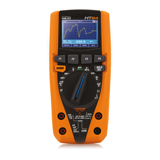
HT64 4. OPERATING INSTRUCTIONS 4.1. DESCRIPTION OF THE INSTRUMENT 4.1.1. Description of the controls CAPTION: 1. LCD display 2. Function key F2 3. Function key F3 4. Function key F1 5. Function key F4 6. RANGE key 7. HOLD/REL key 8. -
Page 10: Description Of Function Keys
HT64 4.2. DESCRIPTION OF FUNCTION KEYS 4.2.1. HOLD/REL key Pressing the HOLD/REL key freezes the value of the measured quantity on the display. After pressing this key, the message Hold appears on the display. Press the HOLD/REL “ ” key again to exit the function. To save the vale on the display, see § 4.3.3. Press and hold the HOLD/REL key for a long time in order to activate/deactivate relative measurement. -
Page 11: Description Of Internal Functions
HT64 4.3. DESCRIPTION OF INTERNAL FUNCTIONS 4.3.1. Description of the display CAPTION: 1. Indication of Automatic/Manual mode 2. Indication of the system's time 3. Indication of battery charge level activation/deactivation of key tone (not associated with continuity test) 4. Indication of measuring unit 5. -
Page 12: Relative Measurement
HT64 4.3.4. Relative measurement Fig. 5: Relative measurement 1. Press and hold the HOLD/REL key to enter relative measurement (see Fig. 5 right – side). The message and symbol appear on the display. “ ” “ ” 2. Press the F4 key to enter the General menu, save the measured result and display it (see §... -
Page 13: Creating And Saving Graphs Of Measurements
HT64 4.3.6. Creating and saving graphs of measurements Fig. 8: Creating and saving a graph of measurements 1. Press the F1 key to enter the section for creating a graph of the quantity to be measured (see Fig. 8 left side). –... - Page 14 HT64 4. Use the F2 or F3 key to select: Setting of recording duration, from 1min to 23h:59min Setting of sampling interval from 1s to 59min:59s 5. Press the F1 key to enable the editing functions and the F2 (+) and F3 (>>) keys to carry out the desired settings.
- Page 15 HT64 15. Use the F2 or F3 key to select the options: Delete all Measurements all snapshots (measurements) are deleted Delete all Recordings all recordings are deleted Delete all Graphs all graphs are deleted. 16.
-
Page 16: English
HT64 General settings of the instrument Format – Fig. 15: Setting the Format Menu 22. Use the F2 or F3 key to select the options: Key tone allows activating/deactivating the tone of the function keys. Numeric Format allows defining the format of the numbers shown on the display among the options: 0.000 (decimal point) and 0,000 (comma) ... - Page 17 HT64 General settings of the instrument Instrument Info – Fig. 17: Display of Menu Instrument Info 25. The instrument shows the following information: Firmware version internal Firmware version Free memory percentage values of the remaining free space in the memory for saving snapshots (SAVE), recordings (REC) and graphs (GRAPH).
- Page 18 HT64 Recalling measured data (snapshots) on the display Fig. 19: Recalling measured data (snapshots) on the display 31. Use the F2 or F3 key to select symbol View M and press the F1 key (see Fig. 19 left “ ” –...
- Page 19 HT64 Help on line on the display Fig. 21: Help on line on the display 40. Use the F2 or F3 key to select symbol Help and press the F1 key (see Fig. 21). “ ” 41. Use the F2 (UP) or F3 (DOWN) to browse the pages of the context on-line help. 42.
-
Page 20: Operating Instructions
HT64 4.4. OPERATING INSTRUCTIONS 4.4.1. DC, AC+DC Voltage measurement CAUTION The maximum input DC voltage is 1000V. Do not measure voltages exceeding the limits given in this manual. Exceeding voltage limits could result in electrical shocks to the user and damage to the instrument. Fig. -
Page 21: Ac Voltage Measurement
HT64 4.4.2. AC Voltage measurement CAUTION The maximum input AC voltage is 1000V. Do not measure voltages exceeding the limits given in this manual. Exceeding voltage limits could result in electrical shocks to the user and damage to the instrument. Fig. -
Page 22: Frequency And Duty Cycle Measurement
HT64 4.4.3. Frequency and Duty Cycle measurement CAUTION The maximum input AC voltage is 1000V. Do not measure voltages exceeding the limits given in this manual. Exceeding voltage limits could result in electrical shocks to the user and damage to the instrument. Fig. -
Page 23: Resistance Measurement And Continuity Test
HT64 4.4.4. Resistance measurement and continuity test CAUTION Before attempting any resistance measurement, cut off power supply from the circuit to be measured and make sure that all capacitors are discharged, if present. Fig. 25: Use of the instrument for resistance measurement and continuity test 1. -
Page 24: Diode Test
HT64 4.4.5. Diode test CAUTION Before attempting any resistance measurement, cut off power supply from the circuit to be measured and make sure that all capacitors are discharged, if present. Fig. 26: Use of the instrument for diode test 1. Select position CAP 2. -
Page 25: Capacitance Measurement
HT64 4.4.6. Capacitance measurement CAUTION Before carrying out capacitance measurements on circuits or capacitors, cut off power supply from the circuit being tested and let all capacitance in it be discharged. When connecting the multimeter and the capacitance to be measured, respect the correct polarity (when required). -
Page 26: Temperature Measurement With K-Type Probe
HT64 4.4.7. Temperature measurement with K-type probe CAUTION Before attempting any temperature measurement, cut off power supply from the circuit to be measured and make sure that all capacitors are discharged, if present. Fig. 28: Use of the instrument for Temperature measurement 1. -
Page 27: Dc, Ac+Dc Current Measurement And E 4-20Ma% Reading
HT64 4.4.8. DC, AC+DC Current measurement and e 4-20mA% reading CAUTION Maximum input DC current is 10A (input 10A) or 600mA (input mAA). Do not measure currents exceeding the limits given in this manual. Exceeding voltage limits could result in electrical shocks to the user and damage to the instrument. -
Page 28: Ac Current Measurement
HT64 4.4.9. AC Current measurement CAUTION Maximum input AC current is 10A (input 10A) or 600mA (input mAA). Do not measure currents exceeding the limits given in this manual. Exceeding voltage limits could result in electrical shocks to the user and damage to the instrument. -
Page 29: Maintenance
HT64 5. MAINTENANCE CAUTION Only expert and trained technicians should perform maintenance operations. Before carrying out maintenance operations, disconnect all cables from the input terminals. Do not use the instrument in environments with high humidity levels or high temperatures. Do not expose to direct sunlight. ... -
Page 30: Replacement Of Internal Fuses
HT64 5.2. REPLACEMENT OF INTERNAL FUSES Fig. 32: Replacement of internal fuses 1. Position the rotary switch to OFF and remove the cables from the input terminals. 2. Turn the fastening screw of the battery compartment cover from position to position “... -
Page 31: Technical Specifications
HT64 6. TECHNICAL SPECIFICATIONS 6.1. TECHNICAL CHARACTERISTICS Accuracy calculated as [%reading + (num. digits*resolution)] at 18°C 28°C <75%HR DC Voltage Protection against Range Resolution Accuracy Input impedance overcharge 600.0mV 0.1mV (0.1%reading + 5digits) 6.000V 0.001V 60.00V 0.01V 1000VDC/ACrms >10M 600.0V 0.1V (0.2%reading + 5digits) - Page 32 HT64 Diode test Function Test current Max voltage with open circuit <1.5mA 3.2VDC Resistance and Continuity test Protection against Range Resolution Accuracy Buzzer overcharge (0.8%reading + 10dgt) 600.0 0.1 6.000k 0.001k 60.00k 0.01k (0.8%reading + 5digits) 1000VDC/ACrms <50 600.0k 0.1k 6.000M...
-
Page 33: Reference Standards
TFT, 6000 dots with bargraph Sampling frequency: 3 times/s 6.2. ENVIRONMENT 6.2.1. Environmental conditions for use 18°C 28°C (64°F 82°F) Reference temperature: 5°C ÷ 40°C (41°F 104°F) Operating temperature: Allowable relative humidity: <80%HR -20° ÷ 60°C (-4°F 140°F) -
Page 34: Assistance
HT64 7. ASSISTANCE 7.1. WARRANTY CONDITIONS This instrument is warranted against any material or manufacturing defect, in compliance with the general sales conditions. During the warranty period, defective parts may be replaced. However, the manufacturer reserves the right to repair or replace the product. Should the instrument be returned to the After-sales Service or to a Dealer, transport will be at the Customer's charge. - Page 36 Fax: +55 19 9979.11325 eMail: info@htinstruments.es eMail: ht@htitalia.it eMail: vendas@ht-instruments.com.br Web: www.htinstruments.es Web: www.ht-instruments.com Web: www.ht-instruments.com.br HT INSTRUMENTS USA LLC HT INSTRUMENTS GMBH HT ITALIA CHINA OFFICE 3145 Bordentown Avenue W3 Am Waldfriedhof 1b 意大利HT中国办事处 08859 Parlin - NJ - USA...
Need help?
Do you have a question about the 64 and is the answer not in the manual?
Questions and answers