Table of Contents
Advertisement
Quick Links
Advertisement
Table of Contents

Related Manuals for HT VEGA74


Summary of Contents for HT VEGA74
- Page 1 © Copyright HT ITALIA 2022 Release EN 1.00 - 16/11/2022...
-
Page 2: Table Of Contents
VEGA74 TABLE OF CONTENTS PRECAUTIONS AND SAFETY MEASURES ............... 3 1.1. Preliminary instructions ..................... 3 1.2. During use ......................... 4 1.3. After use ..........................4 1.4. Definition of measurement (overvoltage) category ............4 GENERAL DESCRIPTION ................... 5 2.1. Foreword ........................... 5 PREPARATION FOR USE ................... - Page 3 VEGA74 11.2. Service ..........................38 12. THEORETICAL APPENDIXES ................... 39 12.1. Voltage Anomalies ......................39 12.2. Supply voltage unbalance ....................39 12.3. Voltage and current Harmonics ..................40 12.4. Definitions of powers and power factors ................. 43 12.5. Measuring method: outlines .................... 46 12.6.
-
Page 4: Precautions And Safety Measures
(such as construction sites, swimming pools, etc.) and higher than 50V in normal environments, since a risk of electrical shock exists. • Only use original HT accessories. The following symbols are used in this manual: CAUTION: observe the instructions given in this manual; improper use could damage the instrument, its components or create dangerous situations for the operator. -
Page 5: During Use
VEGA74 1.2. DURING USE Please carefully read the following recommendations and instructions: CAUTION Failure to comply with the caution notes and/or instructions may damage the instrument and/or its components or be a source of danger for the operator. • Before changing function, disconnect the test leads from the circuit under test. -
Page 6: General Description
VEGA74 2. GENERAL DESCRIPTION 2.1. FOREWORD The instrument is equipped with a TFT color LCD display, with capacitive "touch-screen" that can be handled simply with the touch of a finger by the user and is structured with an icon-based menu allowing the direct selection of measurement functions for quick and intuitive use. -
Page 7: Preparation For Use
VEGA74 3. PREPARATION FOR USE 3.1. INITIAL CHECKS Before shipping, the instrument has been checked from an electric as well as mechanical point of view. All possible precautions have been taken so that the instrument is delivered undamaged. However, we recommend checking it to detect any damage possibly suffered during transport. -
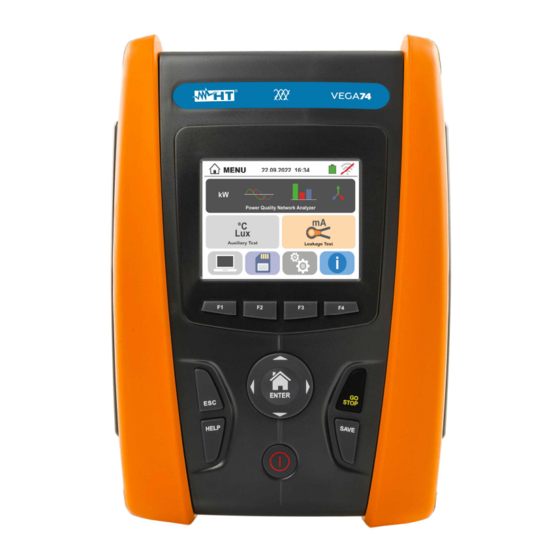
Page 8: Nomenclature
VEGA74 4. NOMENCLATURE 4.1. INSTRUMENT DESCRIPTION CAPTION: 1. Inputs 2. LCD Touch screen display 3. Function keys F1, F2, F3, F4 4. ,, , / ENTER keys 5. Compartment of the connector for optical cable/USB port 6. ESC key 7. -
Page 9: Keyboard Description
INITIAL SCREEN When switching on the instrument, the initial screen appears for a few seconds. It shows: ➢ The HT manufacturer's logo ➢ The instrument model ➢ The Firmware version (LCD and CPU) ➢ The serial number (SN:) of the instrument ➢... -
Page 10: General Menu
VEGA74 5. GENERAL MENU Pressing the ENTER key in any condition of the instrument allows to go back to the general menu in which internal parameters may be set, the saved measures can be displayed and the desired measuring function may be selected. -
Page 11: Operator Name Entry
VEGA74 5.1.3. Operator name entry Touch the icon to enter the name of the operator that will be displayed in the header of each measurement downloaded to PC. The screen to the side appears on the display. ➢ Set the desired name using the virtual keyboard (max 12 characters). -
Page 12: Operating Instructions
VEGA74 6. OPERATING INSTRUCTIONS 6.1. LEAKAGE: LEAKAGE CURRENT MEASUREMENT AND RECORDING This function allows measuring and recording the leakage current in single-phase or three- phase systems by means of the optional accessory HT96U clamp. Fig. 6: Indirect measurement of leakage current in three-phase systems Fig. - Page 13 VEGA74 3. Move the left slide bar cursor in order to select the aggregation time (see § 12.5) among the options: 2s, 5s, 10s, 30s, 1min, 2min, 5min, 10min, 15min, 30min Move the central slide bar cursor (“GO” symbol) to the positions: ➢...
- Page 14 VEGA74 7. Press the GO/STOP key to start recording. The instrument enters stand-by mode (waiting for the next minute or the set date/time) and the “ ” symbol is displayed as shown in the screen to the side. 8. With recording running, the “...
-
Page 15: Aux: Measure And Recording Of Ambient Parameters
VEGA74 6.2. AUX: MEASURE AND RECORDING OF AMBIENT PARAMETERS By means of external transducers, this function allows measuring and recording the following environmental parameters: °C air temperature in °C by means of thermometric transducer °F air temperature in °F by means of thermometric transducer... - Page 16 VEGA74 3. Move the left slide bar cursor in order to select the aggregation time (see § 12.5) among the options: 2s, 5s, 10s, 30s, 1min, 2min, 5min, 10min, 15min, 30min Move the central slide bar cursor (“GO” symbol) to the positions: ➢...
- Page 17 VEGA74 6. Press the GO/STOP key to start recording. The instrument enters stand-by mode (waiting for the next minute or the set date/time) and the “ ” symbol is displayed as shown in the screen to the side. 7. With recording running, the “...
-
Page 18: Pqa: Measurement And Recording Of Main Parameters
VEGA74 6.3. PQA: MEASUREMENT AND RECORDING OF MAIN PARAMETERS In this section the instrument allows the below operations: ➢ Real-time display of numeric values of any electrical parameters of a single-phase and three-phase 3-wire or 4-wire system, harmonic analysis of voltages and currents up to order, power/energies and power peaks absorbed/generated ➢... - Page 19 VEGA74 Fig. 9: Connection for measurement on single-phase 1-2WIRES Fig. 10: Connection for measurement on Three-phase system 3-4WIRES Fig. 11: Connection for measurement on Three-phase system 3-3WIRES EN - 18...
- Page 20 VEGA74 Fig. 12: Connection for measurement on Three-phase system 3-ARON Fig. 13: Connection for measurement on Three-phase system 4-wires 3-High Leg Fig. 14: Connection for measurement on Three-phase system 3-wires 3- Open EN - 19...
- Page 21 VEGA74 Fig. 15: Connection for measurement on Two-phase system 3-wires 3-Y Open Fig. 16: Connection for measurement on Two-phase system 3-wires 3-2El. ½ Fig. 17: Connection for measurement on Two-phase system 3-wires 1- CentrePoint EN - 20...
-
Page 22: General Settings
VEGA74 6.3.2. General settings Touch the icon. The display shows the screen on the right. Touch the icon in order to set: ➢ The type of connection ➢ The nominal reference voltage and the percentage of positive and negative thresholds for the detection of voltage anomalies ➢... - Page 23 VEGA74 3. Move the slide bar cursor in order to select the type of clamp phase current neutral current measurement (marked in blue color), considering that the clamps can be of different types, between the options: ➢ → Flexible transducer clamp type (FLEX) ➢...
-
Page 24: Display Of Measurements
VEGA74 Touch the icon in order to select the pre-set configuration (see § 12.6) among those made available by the instrument. A screen like the one to the side is shown. The following options can be selectable: ➢ EN50160 →... - Page 25 VEGA74 8. The “ ” and “ ” symbols show the Inductive or Capacitive type of the load, respectively. Press the SAVE button or touch the icon to save the measurement on the display as instantaneous snapshot (see § 7.1)
-
Page 26: Start Recording
VEGA74 11. The screen like the one to the side shows the real-time waveforms of voltage and current relevant to a three- phase system. The parameters are indicated with small squares in different colors and the RMS values are shown on the right side. - Page 27 VEGA74 15. The screen shows: ➢ The number of the recording ➢ The date/time of recording start (if automatic) ➢ The date/time of recording stop (if automatic) ➢ The aggregation time set ➢ The number of aggregation intervals recorded ➢ The residual memory capacity in DD-HH-MM ➢...
-
Page 28: List Of Message At Display
VEGA74 6.4. LIST OF MESSAGE AT DISPLAY MESSAGE DESCRIPTION Range: 1..15 Range: 5..999 Range: 0.01..100 Range: 1..500 Range: 0.04..10s Values out of range. Check the setup of instrument Range: 0..199 Range: 1..200 Range: 1..999 Range: 1..3000 Internal synchronization Synchronization error. Switch off and on the instrument Checksum error Communication error. -
Page 29: Operations With The Memory
VEGA74 7. OPERATIONS WITH THE MEMORY 7.1. SAVING MEASUREMENTS The structure of the memory is divided into two independent areas for the SNAPSHOTS section (PQA, LEAKAGE, AUX snapshots – max 999 locations) and for RECORDINGS (PQA, AUX, LEAKAGE recordings). The SNAPSHOTS section memory is of "tree" type with the possibility to expand/hide the nodes, allows the division up to 3 markers nested so as to finalize the precise locations of the measuring points with the insertion of test results. -
Page 30: Recalling And Deleting Snapshots
VEGA74 7.1.2. Recalling and deleting snapshots Touch the icon in the general menu. The screen to the side appears on the display. Touch the icon to recall the measurement result. The following screen appears on the display: Touch the icon to recall and possibly change the comment entered when saving via the internal virtual keyboard. -
Page 31: Recall And Delete Saved Recordings
VEGA74 7.1.3. Recall and delete saved recordings The recordings are automatically saved inside memory at the pressure of GO/STOP key or at the end of set stop date/time. The SAVE key allows saving the instantaneous snapshots show at display during the recording.. -
Page 32: Anomalous Situations
VEGA74 7.1.4. Anomalous situations 1. In case there is no measure saved and the instrument memory is accessed, a screen similar to the one reported here to the side is displayed. 2. In case tries to define a new sub-node over the 3rd... -
Page 33: Connecting The Instrument To A Pc
C2006 or by means a WiFi connection. Before making the connection in USB mode, it is necessary to install on the PC the management software TopView downloadable from the www.ht-instruments.com/download website. To transfer stored data to PC keep to the following procedure: Connection to PC via optical/USB cable 1. -
Page 34: Maintenance
VEGA74 9. MAINTENANCE 9.1. GENERAL INFORMATION ➢ While using and storing the instrument, carefully observe the recommendations listed in this manual in order to prevent possible damage or danger during use. ➢ Do not use the instrument in environments with high humidity levels or high temperatures. -
Page 35: Technical Specifications
VEGA74 TECHNICAL SPECIFICATIONS Accuracy is calculated as: ±[%reading + (no. of digits) * resolution] at 23°C, <80%RH. 10.1. TECHNICAL CHARACTERISTICS AUX AND LEAKAGE SECTIONS Leakage current (input I1 – STD clamp) FS AC Clamp [A] Resolution [A] Accuracy 0.1mA 1< FS < 10 0.01A... -
Page 36: Technical Characteristics Pqa Section
VEGA74 TECHNICAL CHARACTERISTICS PQA SECTION 10.2. DC/AC TRMS Voltage (Phase-Neutral) Range [V] Resolution [V] Accuracy 15.0 380.0 (1.0rdg + 1dgt) 0.1V Crest factor: 1,5 ; Frequency: 42 69.0 Hz DC/AC TRMS Voltage (Phase-Phase) Range [V] Resolution [V] Accuracy 15.0 ... - Page 37 VEGA74 Reactive power (@ 230V, I> 5% FS, cos<0.9, f=50.0Hz) FS clamp Range [kVAr] Resolution [kVAr] Accuracy 0.000 9.999 0.001 10A 10.00 99.99 0.01 0.00 99.99 0.01 10A < FS 200 100.0 999.9 (2.0rdg + 7dgt) 0.0 ...
-
Page 38: Reference Guidelines
VEGA74 10.3. REFERENCE GUIDELINES Safety: IEC/EN61010-1, IEC/EN61557-1 EMC : IEC/EN61326-1 EMC ambient of use : industrial, Class A, Group 1 Technical documentation: IEC/EN61187 Safety of measuring accessories: IEC/EN61010-031, IEC/EN61010-2-032 Insulation: double insulation Pollution level: Protection index: IP40 Measurement category: CAT IV 300V to ground, CAT III 350V to ground... -
Page 39: Service
VEGA74 SERVICE 11.1. WARRANTY CONDITIONS This instrument is warranted against any material or manufacturing defect, in compliance with the general sales conditions. During the warranty period, defective parts may be replaced. However, the manufacturer reserves the right to repair or replace the product. -
Page 40: Theoretical
VEGA74 THEORETICAL APPENDIXES 12.1. VOLTAGE ANOMALIES The meter is capable of recording independently by the aggregation time all those TRMS values as voltage anomalies (sags, swells), calculated every 20ms, beyond the percentage thresholds of Voltage Reference (Vref) set during the programming from ±3% to ±30% with steps of 1%. -
Page 41: Voltage And Current Harmonics
VEGA74 12.3. VOLTAGE AND CURRENT HARMONICS Any periodical non-sine wave can be represented as a sum of sinusoidal waves having each a frequency that corresponds to an entire multiple of the fundamental, according to the relation: where: = average value of v(t) - Page 42 VEGA74 Odd harmonics Even harmonics Not multiple of 3 Multiple of 3 Relative voltage % Order h Relative voltage Relative voltage Order h Order h % Max % Max 6..24 Table 1 Limits for the harmonic voltages the supplier may introduce into the network...
- Page 43 VEGA74 Presence of harmonics: consequences In general, even harmonics, i.e. the 2 etc., do not cause problems. Triple harmonics, odd multiples of three, are added on the neutral (instead of cancelling each other) thus creating a condition of overheating of the wire which is extremely dangerous. Designers...
-
Page 44: Definitions Of Powers And Power Factors
VEGA74 12.4. DEFINITIONS OF POWERS AND POWER FACTORS In a standard electrical installation powered by three sine voltages the following are to be defined: cos( Phase Active Power: (n=1,2,3) Phase Apparent Power: (n=1,2,3) Phase Reactive Power: (n=1,2,3) Phase Power Factor:... - Page 45 VEGA74 NOTES ➢ It shall be noted that the expression of the phase Reactive Power with no sine waveforms, would be wrong. To understand this, it may be useful to consider that both the presence of harmonics and the presence of reactive power produce, among other effects, an increase of line power losses due to the increased current RMS value.
- Page 46 VEGA74 Value Description The active power (positive or negative) is defined in the panel and therefore acquires the value Pact of the active power in that moment. The reactive power (inductive or capacitive, positive or negative) is defined in the panel and Preact therefore acquires the value of the reactive power in that moment.
-
Page 47: Measuring Method: Outlines
VEGA74 12.5. MEASURING METHOD: OUTLINES The meter is capable of measuring: voltages, currents, active powers, inductive and capacitive reactive powers, apparent powers, inductive and capacitive power factors, energies, analogical or pulse parameters. All these parameters are analysed in a digital way for each phase (voltage and current) and calculated based on formulas of the previous sections. -
Page 48: Description Of Typical Configurations
VEGA74 12.6. DESCRIPTION OF TYPICAL CONFIGURATIONS During each recording, as a not modifiable option, the instrument always automatically saves, as a standard configuration, besides voltage anomalies, the values of any network parameter depending on the type of selected electric system (see 6.3.1). - Page 49 VEGA74 HARM Description Settings System type: Not modified Frequency: Not modified Clamp type: Not modified Full scale clamp: Not modified TV ratio: Not modified Start recording: Not modified Stop recording: Not modified Aggregation time: 10min Voltage anomalies recordings: Selected Reference voltage anomalies (Vn):...
- Page 50 VEGA74 kWh (POWER & ENERGY) Description Settings System type: Not modified Frequency: Not modified Clamp type: Not modified Full scale clamp: Not modified TV ratio: Not modified Start recording: Not modified Stop recording: Not modified Aggregation time: 15min Voltage anomalies recordings:...
- Page 51 VEGA74 DEFAULT Description Settings System type: Not modified Frequency: Not modified Clamp type: Not modified Full scale clamp: Not modified TV ratio: Not modified Start recording: Not modified Stop recording: Not modified Aggregation time: Not modified Voltage anomalies recordings: Selezionata...
- Page 52 VEGA74 Three-phase 4-wires 3-High Leg systems – for USA systems EN50160 Description Settings System type: Not modified Frequency: Not modified Clamp type: Not modified Full scale clamp: Not modified TV ratio: Not modified Start recording: Not modified Stop recording: Not modified...
- Page 53 VEGA74 kWh (POWER & ENERGY) Description Description System type: Not modified Frequency: Not modified Clamp type: Not modified Full scale clamp: Not modified TV ratio: Not modified Start recording: Not modified Stop recording: Not modified Aggregation time: 15min Voltage anomalies recording:...
- Page 54 VEGA74 Three-phase 3-wires 3-Y Open, 3-2El. ½, 1-CentralPoint – for USA systems EN50160 Description Description System type: Not modified Frequency: Not modified Clamp type: Not modified Full scale clamp: Not modified TV ratio: Not modified Start recording: Not modified Stop recording:...
- Page 55 VEGA74 kWh (POWER & ENERGY) Description Description System type: Not modified Frequency: Not modified Clamp type: Not modified Full scale clamp: Not modified TV ratio: Not modified Start recording: Not modified Stop recording: Not modified Aggregation time: 15min Voltage anomalies recording:...
- Page 56 VEGA74 DEFAULT Description Description System type: Not modified Frequency: Not modified Clamp type: Not modified Full scale clamp: Not modified TV ratio: Not modified Start recording: Not modified Stop recording: Not modified Aggregation time: Not modified Voltage anomalies recording: Selected...
- Page 57 VEGA74 Three-phase 3-wire 3-ARON and 3- Open (USA system) EN50160 Description Description System type: Not modified Frequency: Not modified Clamp type: Not modified Full scale clamp: Not modified TV ratio: Not modified Start recording: Not modified Stop recording: Not modified...
- Page 58 VEGA74 kWh (POWER & ENERGY) Description Description System type: Not modified Frequency: Not modified Clamp type: Not modified Full scale clamp: Not modified TV ratio: Not modified Start recording: Not modified Stop recording: Not modified Aggregation time: 15min Voltage anomalies recording:...
- Page 59 VEGA74 DEFAULT Description Description System type: Not modified Frequency: Not modified Clamp type: Not modified Full scale clamp: Not modified TV ratio: Not modified Start recording: Not modified Stop recording: Not modified Aggregation time: Not modified Voltage anomalies recording: Selected...
- Page 60 Fax: +55 19 9979.11325 eMail: info@htinstruments.es eMail: ht@htitalia.it eMail: vendas@ht-instruments.com.br Web: www.htinstruments.es Web: www.ht-instruments.com Web: www.ht-instruments.com.br HT INSTRUMENTS USA LLC HT INSTRUMENTS GMBH HT ITALIA CHINA OFFICE 3145 Bordentown Avenue W3 Am Waldfriedhof 1b 意大利 HT 中国办事处 08859 Parlin - NJ - USA...
Need help?
Do you have a question about the VEGA74 and is the answer not in the manual?
Questions and answers