Table of Contents
Advertisement
Quick Links
Advertisement
Table of Contents

Related Manuals for HT HT9023


Summary of Contents for HT HT9023
- Page 1 ENGLISH User manual Copyright HT ITALIA 2020 Release EN 1.01 - 03/07/2020...
-
Page 2: Table Of Contents
HT9023 TABLE OF CONTENTS PRECAUTIONS AND SAFETY MEASURES ............... 3 1.1. Preliminary instructions ..................... 3 1.2. During use ......................... 4 1.3. After use ..........................4 1.4. Definition of measurement (overvoltage) category ............4 GENERAL DESCRIPTION ................... 5 ... - Page 3 HT9023 8.3. Accessories ........................53 8.3.1. Accessories provided ........................53 SERVICE ........................54 9.1. Warranty conditions ......................54 9.2. Service ..........................54 APPENDIX – THEORETICAL OUTLINE ..............55 10.1. Voltage and current harmonics ..................55 ...
-
Page 4: Precautions And Safety Measures
HT9023 1. PRECAUTIONS AND SAFETY MEASURES The instrument has been designed in compliance with directive IEC/EN61010-1 relative to electronic measuring instruments. For your safety and in order to avoid damaging the instrument, please carefully follow the procedures described in this manual and read all notes preceded by the symbol paying the utmost attention. -
Page 5: During Use
HT9023 1.2. DURING USE Please carefully read the following recommendations and instructions: CAUTION Failure to comply with the Caution notes and/or Instructions may damage the instrument and/or its components or be a source of danger for the operator. Before activating the switch, remove the conductor from the clamp jaw or disconnect the test leads from the circuit under test. -
Page 6: General Description
HT9023 2. GENERAL DESCRIPTION The instrument carries out the following measurements: DC voltage up to 1500V AC, AC+DC TRMS voltage up to 1000V “Voltsense” sensor for detection AC voltage without contact DC, AC, AC+DC TRMS current up to 1000A ... -
Page 7: Preparation For Use
HT9023 3. PREPARATION FOR USE 3.1. INITIAL CHECKS Before shipping, the instrument has been checked from an electric as well as mechanical point of view. All possible precautions have been taken so that the instrument is delivered undamaged. However, we recommend generally checking the instrument in order to detect possible damage suffered during transport. -
Page 8: Nomenclature
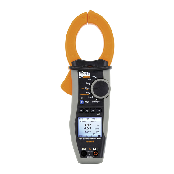
HT9023 4. NOMENCLATURE 4.1. INSTRUMENT DESCRIPTION CAPTION: 1. Inductive clamp jaw 2. AC voltage indicator LED 3. Jaw trigger 4. Rotary selector switch 5. H/ESC/ 6. F1,F2,F3,F4/OK function keys 7. LCD display 8. Input terminal V 9. Input terminal COM Fig. -
Page 9: Hand Protection
HT9023 4.1.2. Hand protection CAPTION: 1. Hand protection 2. Safe area Fig. 3: hand protection Always keep your hands under the hand protection. This protection is always located in a suitable position to guarantee a correct safety distance from possible exposed or live parts (see Fig. -
Page 10: Function Keys Description
HT9023 4.2. FUNCTION KEYS DESCRIPTION 4.2.1. F1, F2, F3, F4/OK keys The F1, F2, F3, F4/OK keys perform different functions according to the measurement set (for detailed information, see the single functions). 4.2.2. H/ESC/ A single press activates the Data HOLD function and the value of the measurement quantity is frozen at display. -
Page 11: Instrument Settings
HT9023 4.4. INSTRUMENT SETTINGS By positioning the selector switch to “Settings”, the screen aside will appear, containing the possible settings of the instrument. G e n e r a l D a t e / T i m e Press F2, F3 (,) keys to modify the settings of the selected... -
Page 12: Log Menu
HT9023 4.4.3. Log menu By selecting the “Log” item the instrument shows the screen aside will appear. Press the F2, F3 (, ) keys to modify the settings of the Integration Period parameter (aggregation time I n t . P e r i o d : between two consecutive saving inside a recording operation). -
Page 13: Memory Irc
HT9023 4.4.6. Memory IRC In the "Memory IRC" section there is a list of all the inrush current measurements saved by the instrument (see § 5.6). The I 0 1 : 1 3 / 1 2 - 1 0 . 4 1 : 2 0 screen like the one on the side is shown on the display. -
Page 14: Operative Instructions
HT9023 5. OPERATIVE INSTRUCTIONS 5.1. AC VOLTAGE DETECTION With the selector switch set to “V ” by taking the end of the clamp jaw near an AC source, the red LED at the base of the clamp jaw will turn on (see Fig. 1 – part 2), which indicates that voltage is present. - Page 15 HT9023 2. Press F1 (Mod) key to open the drop-down menu shown on Har Fnc the screen nearby and select the “DC” option with the same < 4 2 . 5 H z 3. Press the F4 (OK) to confirm.
-
Page 16: Ac And Ac+Dc Voltage Measurement
HT9023 5.3. AC AND AC+DC VOLTAGE MEASUREMENT CAUTION The maximum AC and AC+DC input voltage is 1000V. When the display shows “> 999.9V”, it means that the maximum value which clamp is capable of measuring has been exceeded. Exceeding these limits could result in electrical shocks to the user and damage to the instrument. - Page 17 HT9023 4. Connect red cable to input lead V and black cable to input lead COM then position the leads to the desired points of the circuit under test (see Fig. 6) 5. The screen shows an example of AC voltage measurement.
-
Page 18: Voltage Harmonics Measurement
HT9023 5.3.1. Voltage Harmonics measurement 1. Press F2 (Har) key to select the screen of voltage harmonics Har Fnc as shown nearby. Press again F2 (RMS) to go back to 5 0 . 0 H z voltage measurement screen 2 2 0 . 5 17/01 –... -
Page 19: Phase Sequence And Phase Conformity With 1 Wire
HT9023 5.3.2. Phase Sequence and Phase Conformity with 1 wire CAUTION While measuring, the instrument must be held in the operator’s hand. Phase sequence test Fig. 7: Verification of phase sequence 1. Press F1 (Mod) to open the drop-down menu shown on the Har Fnc screen nearby and select the “Ph Seq”... - Page 20 HT9023 3. The instrument shows the “PH1” message and waits for the detection of L1 phase P h S e q 4. Connect red cable to input lead V and black cable to input lead COM then position the leads respectively to the L1...
- Page 21 HT9023 sound signal (buzzer) and the message “Meas” is displayed. P h S e q Do not press any key and keep the test lead connected to L2 phase cable P H 2 M e a s 17/01 – 18:34:23 9.
- Page 22 HT9023 Phase conformity test CAUTION While measuring, the instrument must be held in the operator’s hand. Fig. 8: Verification of phase conformity 1. The instrument shows the screen nearby, and waits for the detection of L1 phase of the first system P h S e q 2.
- Page 23 HT9023 3. When a voltage ≥ 100V is detected, the instrument emits a sound signal (buzzer) and the message “Meas” is displayed. P h S e q Do not press any key and keep the test lead connected to L1...
-
Page 24: Dc Current Measurement
HT9023 5.4. DC CURRENT MEASUREMENT CAUTION The maximum measurable DC current is 1000A. When the display shows “> 999.9A”, it means that the maximum value that the clamp is capable of measuring has been exceeded. Exceeding these limits could result in electrical shocks to the user and damage to the instrument ... - Page 25 HT9023 2. Press F1 (Mod) to open the drop-down menu shown on the Har Fnc screen aside and select the “DC” option with the same key. < 4 2 . 5 H z The F2 (Har) key is not active in this function 3.
-
Page 26: Ac And Ac+Dc Current Measurement
HT9023 5.5. AC AND AC+DC CURRENT MEASUREMENT CAUTION The maximum measurable AC/AC+DC current is 1000A. When the display shows “> 999.9A”, it means that the maximum value that the clamp is capable of measuring has been exceeded. Exceeding these... - Page 27 HT9023 2. Press F1 (Mod) to open the drop-down menu shown on the Har Fnc screen nearby and select the “AC” or “AC+DC” option with < 1 0 . 5 H z the same key 3. Press F4 (OK) to confirm.
-
Page 28: Current Harmonics Measurement
HT9023 5.5.1. Current Harmonics measurement 1. Press the F2 (Har) key to select the screen of current Har Fnc harmonics as shown nearby. Press again the F2 (RMS) to go 5 0 . 0 H z back to current measurement screen 1 0 0 . -
Page 29: Dynamic Inrush Current Measurement
HT9023 5.6. DYNAMIC INRUSH CURRENT MEASUREMENT CAUTION The maximum measurable AC or AC+DC current is 1000A. Do not measure currents exceeding the limits given in this manual. Exceeding these limits could result in electrical shocks to the user and damage to the instrument. - Page 30 HT9023 between the “Inrush 100A” (for inrush current <100A) or D y n a m i c FS 100A “Inrush 1000A” (for inrush current <1000A) options as FS 1000A shown asideress F4 (OK) to confirm. Select the "Zro" option to deleting any possible residual magnetization...
- Page 31 HT9023 Press the F4 (Sav) key to save the measurement result within the IRC memory (see § 4.4.6). It is possible to save up D y n a m i c to 20 IRC measurements in the memory. Then the message 100ms "MEM FULL"...
-
Page 32: Dc Power And Energy Measurement
HT9023 5.7. DC POWER AND ENERGY MEASUREMENT CAUTION The maximum DC input voltage is 1500V and the maximum measurable DC current is 1000A. Do not measure voltages and currents exceeding the limits given in this manual. Exceeding these limits could result in electrical shocks to the user and damage to the instrument ... - Page 33 HT9023 2. Press F1 (Mod) to open the drop-down menu shown on the Par Fnc screen aside and select the “DC” option with the same key AC+DC 1P < 4 2 . 5 H z 3. Press F4 (OK) to confirm.
- Page 34 HT9023 8. Press F2 (Par) to open the drop-down menu shown on the screen aside and select the “Energy” option for the DC Power energy measurement. Confirm with F4 (OK). The following Volt/Curr screen is displayed Energy 1 . 6 0 17/01 –...
- Page 35 HT9023 Press the F3 (Fnc) key, select the "Stop Log" option and Par Fnc confirm with the F4 (OK) key to end the energy Stop Log measurement. The recording is automatically saved in Info the internal memory of the instrument and the reference is visible in the "Memory REC"...
-
Page 36: Ac And Ac+Dc Power And Energy Measurement
HT9023 5.8. AC AND AC+DC POWER AND ENERGY MEASUREMENT CAUTION The maximum AC/AC+DC input voltage is 1000V and the maximum measurable AC/AC+DC current is 1000A. Do not measure voltages and currents exceeding the limits given in this manual. Exceeding these limits could result in electrical shocks to the user and damage to the instrument ... - Page 37 HT9023 2. Press F1 (Mod) to open the drop-down menu shown on the Par Fnc screen aside and select the “AC+DC 1P” (Single phase AC+DC 1P < 4 2 . 5 H z measurement) or “AC+DC 3P” (balanced Three phase...
- Page 38 HT9023 9. Press F2 (Par) to open the drop-down menu shown on the screen aside and select the “Volt/Curr” option for the P-Q-S voltage and current measurement. Confirm with F4 (OK). PF-DPF The following screen is displayed. Volt/Curr Harm Voltage 1 .
- Page 39 HT9023 14. Pressing F1 (◄) or F4 (►) it is possible to move the cursor ◄ ► Par Fnc over the graph and to select the harmonic to be measured. The correspondent absolute or percentage value of harmonic current is displayed. It is possible to measure up to the 25...
- Page 40 HT9023 18. Press F3 (Fnc), select the “Start Log” option and confirm Par Fnc with F4 (OK) key in order to activate the energy A C + D C 5 0 . 0 H z measurement with set integration period (see § 4.4.3)
- Page 41 HT9023 23. While measuring P-Q-S power or PF-DPF, press F3 (Fnc) to open the drop-down menu shown on the screen aside. At 5 0 . 0 H z each subsequent pressure of F3, the cursor will scroll 2 1 . 4 7 through the available items, as follows: 7 .
-
Page 42: Resistance And Continuity Test Measurement
HT9023 5.9. RESISTANCE AND CONTINUITY TEST MEASUREMENT CAUTION Before attempting any resistance measurement, remove power from the circuit under test and discharge all capacitors, if present. Fig. 14: Resistance measurement 1. Positioning the selector switch to “ ”, the screen aside will appear. - Page 43 HT9023 2. Press F1 (Mod) to open the drop-down menu shown on the screen aside and select the “Resistance” option with the Resistance same key Continuity 3. Press F4 (OK) to confirm. The instrument goes into Help resistance measurement mode >...
-
Page 44: Connection Of Instrument To Pc And Mobile Devices
HT9023 6. CONNECTION OF INSTRUMENT TO PC AND MOBILE DEVICES The connection between the PC and the instrument via WiFi connection which should be activated during the execution of the operations. Before connecting it is necessary that the TopView management software supplied must be installed on the PC and the presence of an active and working WiFi device (e.g: WiFi key) must be checked. - Page 45 HT9023 Search for the “HT9023_xxxxxxxx” instrument in the WiFi device included on the PC and connect it as shown as an example in the following Fig. 15 Fig. 15: WiFi connection of instrument to PC (example) Launch the TopView software, open the "PC-Instrument connection" section, run the "Find the instrument"...
- Page 46 HT9023 Click on the “Next” button to open the download window (see Fig. 17). Check the measurements you want to download, choose the path where you want to save them and click on the "Download" button to start the transfer Fig.
-
Page 47: Real-Time Readings
HT9023 6.2. REAL-TIME READINGS Position the selector on “ W ”, select the F4 (OK) key with Modd Par Fnc the F1 (Mod) key and F4 (OK) key the "AC + DC 1P", "AC + AC+DC 1P < 4 2 . 5 H z DC 3P"... - Page 48 HT9023 Fig. 19:Real-time connection of the instrument Click on the "Next" button to open the real-time visualization of values in the form of tables, waveforms, harmonics graphs and vector diagram, as shown in the Fig. 20 Fig. 20: Real-time visualization of parameters Press the F1 (Mod) key, select the "Esc"...
-
Page 49: Connection To Mobile Devices
HT9023 6.3. CONNECTION TO MOBILE DEVICES The instrument can be connected via WiFi to Android/iOS smartphone and/or tablet devices for the transfer of measurement data via HTAnalysis APP. Operate as follows: Download and install the HTAnalysis on the desired mobile device (Android/iOS) Put the instrument in data transfer mode via WiFi (see §... -
Page 50: Maintenance
HT9023 7. MAINTENANCE 7.1. GENERAL INFORMATION 1. The instrument you purchased is a precision instrument. While using and storing the instrument, carefully observe the recommendations listed in this manual in order to prevent possible damage or danger during use. 2. Do not use the instrument in environments with high humidity levels or high temperatures. -
Page 51: Technical Specifications
HT9023 8. TECHNICAL SPECIFICATIONS 8.1. TECHNICAL CHARACTERISTICS Accuracy indicated as ±[%rdg + (num digit * resolution)] referred to 23°C ± 5°C, < 80%RH DC Voltage Range [V] Resolution [V] Accuracy Overload protection -1500.0 1500.0 (1.0%rdg+3dgt) 1500VDC Input impedance: 1MΩ;... - Page 52 HT9023 Phase sequence and phase conformity Range [V] Frequency [Hz] Overload protection 100 1000 45 66 1000VDC/ACrms Input impedance: 1.3MΩ Inrush current (DC, AC+DC TRMS) Overload protection Range [A] Resolution [A] Accuracy (*) 1.0 99.9A 0.1A (2.0%rdg + 5dgt) 1000ADC/ACrms 10 ...
-
Page 53: Reference Guidelines
HT9023 8.1.1. Reference guidelines Safety: IEC/EN61010-1, IEC/EN61010-2-032 EMC : IEC/EN61326-1 Technical documentation: IEC/EN61187 Safety of measuring accessories: IEC/EN61010-31 Insulation: double insulation Pollution level: Measurement category: CAT IV 600V/CAT III 1000V to ground 8.1.2. General characteristics Mechanical characteristics Dimensions (L x W x H):... -
Page 54: Environment
HT9023 8.2. ENVIRONMENT 8.2.1. Environmental conditions for use Reference calibration temperature: 23°C ± 5°C (73 ± 41°F) Operating temperature: 0°C ÷ 40°C (32 ÷ 104°F) Allowable relative humidity: <80%RH Storage temperature: -10°C ÷ 60°C (14 ÷ 140°F) Storage humidity: <70%RH... -
Page 55: Service
HT9023 9. SERVICE 9.1. WARRANTY CONDITIONS This equipment is guaranteed against material faults or production defects, in accordance with the general sales conditions. During the warranty period (one year), faulty parts may be replaced. The manufacturer reserves the right to decide either to repair or replace the product. -
Page 56: Appendix - Theoretical Outline
HT9023 APPENDIX – THEORETICAL OUTLINE 10.1. VOLTAGE AND CURRENT HARMONICS Any periodic non-sinusoidal wave may be represented by a sum of sinusoidal waves, each with a frequency which is a whole multiple of the fundamental, according to the relationship: ... - Page 57 HT9023 Limit values for harmonics Standard EN50160 prescribes the limits for the Voltage Harmonics that Energy Provider may introduce into the network. Under normal operating conditions, at any time in a week, 95% of the efficient values of each harmonic voltage, averaged to 10 minutes, must be lower than or equal to the values indicated in the following Table ...
- Page 58 HT9023 Consequence resulting from presence of harmonics Generally, harmonics of even, 2 etc. order do not create problems. Designers must consider the following points when designing a power distribution system containing harmonic currents: Installation parts Effects traceable to Harmonics Non-uniform heating of internal fuse element and consequent overheating which can also lead to Fuses an explosion of the fuse casing.
Need help?
Do you have a question about the HT9023 and is the answer not in the manual?
Questions and answers