Table of Contents
Advertisement
Quick Links
Advertisement
Table of Contents

Related Manuals for HT PVCHECKs-PRO


Summary of Contents for HT PVCHECKs-PRO
- Page 1 Copyright HT ITALIA 2023 Release EN 1.00 - 06/10/2023...
-
Page 3: Table Of Contents
PVCHECKs-PRO TABLE OF CONTENTS PRECAUTIONS AND SAFETY MEASURES ............... 3 1.1. Preliminary instructions ..................... 3 1.2. During use ......................... 4 1.3. After use ..........................4 1.4. Definition of measurement (overvoltage) category ............4 GENERAL DESCRIPTION ................... 5 ... - Page 4 PVCHECKs-PRO TECHNICAL SPECIFICATIONS ................57 10.1. Technical characteristics ....................57 10.2. General characteristics ....................58 10.3. Environmental conditions for use ..................59 10.4. Accessories ........................59 APPENDIX – THEORETICAL OUTLINE ..............60 11.1. Measurement of polarization index (PI) ................60 ...
-
Page 5: Precautions And Safety Measures
PVCHECKs-PRO 1. PRECAUTIONS AND SAFETY MEASURES The instrument has been designed in compliance with directive IEC/EN61010-1 relevant to electronic measuring instruments. Before and while carrying out measurements, observe the following indications and read all notes preceded by the symbol with the utmost attention. -
Page 6: During Use
PVCHECKs-PRO 1.2. DURING USE Please carefully read the following recommendations and instructions: CAUTION Failure to comply with the caution notes and/or instructions may damage the instrument and/or its components or be a source of danger for the operator. The symbol “ ” indicates a full charge level of the internal batteries. When battery charge decreases to a minimum level, the symbol “... -
Page 7: General Description
PVCHECKs-PRO 2. GENERAL DESCRIPTION 2.1. FOREWORD This instrument has been designed to carry out quick tests (IVCK) on photovoltaic (PV) modules/strings in compliance with standard IEC/EN62446. 2.2. INSTRUMENT FUNCTIONS The instrument has the following features: Continuity test of protective conductors (RPE) ... -
Page 8: Preparation For Use
PVCHECKs-PRO 3. PREPARATION FOR USE 3.1. INITIAL CHECKS Before shipping, the instrument has been checked from an electric as well as a mechanical point of view. All possible precautions have been taken so that the instrument is delivered undamaged. However, we recommend checking it to detect any damage possibly suffered during transport. -
Page 9: Nomenclature
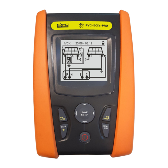
PVCHECKs-PRO 4. NOMENCLATURE 4.1. DESCRIPTION OF THE INSTRUMENT CAPTION: 1. Inputs 2. LCD display 3. Keys ,,,, SAVE/ENTER 4. Compartment connector optical/USB cable 5. Key GO/STOP 6. Key HELP/ 7. Key ESC/MENU 8. Key ON/OFF Fig. 1: Description of the front part of the instrument CAPTION: 1. -
Page 10: Keyboard Description
When switching on the instrument, the initial screen appears for a few seconds. It shows: P V C H E C K s - P R O The instrument model (PVCHECKs-PRO) The manufacturer’s name H T I T A L I A ... -
Page 11: General Menu
PVCHECKs-PRO 5. GENERAL MENU Pressing the ESC key in any condition of the instrument allows going back to the general menu, in which internal parameters may be set and the desired measuring function may be selected. Use the cursor to select one of the options and confirm with ENTER to access the desired function. -
Page 12: Date And Time
PVCHECKs-PRO 5.1.2. Date and time Move the cursor to Date and time by using the arrow keys 15/10 – 18:04 (,) and confirm with ENTER. Subsequently, the screen to : F or m a t the side appears, so that the system’s date/time can be set. -
Page 13: Operator Name
PVCHECKs-PRO 5.1.6. Operator name This option allows including the name of the operator who carried out the measurements using the instrument (max 12 digits). The chosen name will be included in the reports created by using the management software. 1. Use the arrow keys or to move the cursor to the SAVE 15/10 –... -
Page 14: Operating Instructions
PVCHECKs-PRO 6. OPERATING INSTRUCTIONS 6.1. DMM – MULTIMETER FUNCTION In this function, the instrument shows the RMS (root mean square) and DC (average) values of voltages between the positive (+) and negative (-) pole, between the positive (+) pole and earth connection (PE) and between the negative (-) pole and earth connection (PE), in order to check for the presence of AC components on input voltages. -
Page 15: Urem - Remote Unit
PVCHECKs-PRO 6.2. UREM – REMOTE UNIT This section manages all operations which can be performed by using the remote unit SOLAR03, which can also be used for IVCK measurements. In particular, it is possible to: Through Bluetooth connection, search for a remote unit SOLAR03, which can be managed by the instrument, adding it to the instrument’s internal list (max 5 remote units);... - Page 16 PVCHECKs-PRO 4. On the remote unit SOLAR03, activate “Pairing” (refer to UREM 15/10 – 18:04 SOLAR03 Stat. user manual of remote unit SOLAR03), so that it can be recognized by the instrument. Once done, the serial number of the remote unit and the message “Remote unit S O L A R 0 3 S N : 2 3 0 5 1 2 0 3 detected.
- Page 17 PVCHECKs-PRO 11. Use the arrow keys or to select “Info” to display the UREM 15/10 – 18:04 following information on the active and connected remote R e m o t e u n i t unit SOLAR03: S O L A R 0 3 ...
-
Page 18: Rpe - Continuity Measurement On Pv Modules/Strings/Fields
PVCHECKs-PRO 6.3. RPE – CONTINUITY MEASUREMENT ON PV MODULES/STRINGS/FIELDS The purpose of this measurement is performing a continuity test of the protective and equipotential conductors (e.g.: from rod to earth and connected foreign earth) and earth rods of SPDs on PV installations. The test must be carried out using a test current >... - Page 19 PVCHECKs-PRO 4. Use the arrow keys or and select the position “><”. 15/10 – 18:04 The display shows the screen to the side. - - - I t e s t - - - - - - ...
-
Page 20: Carrying Out Continuity Measurements In Standard (Std) Mode
PVCHECKs-PRO 6.3.2. Carrying out continuity measurements in Standard (STD) mode 1. Position the cursor onto RPE by using the arrow keys 15/10 – 18:04 (,) and confirm with ENTER. The display shows the - - - following screen. The symbol “STD” is shown on the display. - Page 21 PVCHECKs-PRO 6. Press the GO/STOP key to start the test. In case no error 15/10 – 18:04 conditions occur, the instrument displays the message - - - “Measuring…” as shown in the screen to the side. I t e s t - - - Measuring…...
-
Page 22: Carrying Out Continuity Measurements In Timer (Tmr) Mode
PVCHECKs-PRO 6.3.3. Carrying out continuity measurements in Timer (TMR) mode 1. Position the cursor onto RPE by using the arrow keys 15/10 – 18:04 (,) and confirm with ENTER. The display shows the - - - following screen. 2. Use the arrow keys (,) to select the Timer mode. The... - Page 23 PVCHECKs-PRO 9. Press the GO/STOP key to start the test. In case no error 15/10 – 18:04 conditions occur, the instrument starts a series of 0 . 2 3 continuous measurements for the entire duration of the set Timer, emitting a short sound every 3s, and...
-
Page 24: Anomalous Situations
PVCHECKs-PRO 6.3.4. Anomalous situations 1. To zero the value of compensated resistance, carry out a 15/10 – 18:04 new compensation procedure with a resistance higher - - - than 5 as, for example, with open leads. The message “Zero Reset” appears on the display. -
Page 25: M - Measurement Of Insulation On Pv Modules/Strings/Fields
PVCHECKs-PRO 6.4. M – MEASUREMENT OF INSULATION ON PV MODULES/STRINGS/FIELDS The purpose of this function is measuring the insulation resistance of the active conductors of PV modules, strings and fields according to the prescriptions of standards IEC/EN62446-1 and IEC/EN61557-2, with no need to use an external switch to short- circuit the positive and negative terminals. - Page 26 PVCHECKs-PRO 4. Use the arrow keys or and select the position “Lim.”. M 15/10 – 18:04 ( + ) ( - ) The display shows the screen to the side. V t e s t - - - - - - 5.
-
Page 27: Measuring Insulation - Tmr Mode
PVCHECKs-PRO 7. Press and hold the GO/STOP key for at least 3s in M 15/10 – 18:04 ( + ) ( - ) order to start the test. In case no error conditions occur, V t e s t - - - - - - the instrument displays the message “Measuring…”... - Page 28 PVCHECKs-PRO 4. Use the arrow keys or and select the position “Lim.”. M 15/10 – 18:04 V t e s t ( - ) - - - The display shows the screen to the side. M R i ( - ) - - - 5.
- Page 29 PVCHECKs-PRO 9. Press and hold the GO/STOP key for at least 3s in M 15/10 – 18:04 V t e s t ( - ) - - - order to start the test. In case no error conditions occur, M ...
-
Page 30: Anomalous Situations
PVCHECKs-PRO 6.4.3. Anomalous situations 1. In case the instrument detects one of the following M 15/10 – 18:04 ( + ) ( - ) conditions: “|VPN| > 1500V”, “|VPE| > 1500V” or “|VNE| > V t e s t - - - - - - 1500V”, it stops measuring, gives out a long sound, and... - Page 31 PVCHECKs-PRO 5. In case the instrument detects that the voltage between M 15/10 – 18:04 ( + ) ( - ) the positive and the negative pole is higher than the set V t e s t 1 5 2 0 1 5 1 0 test voltage, the message “VPN>Vtest”...
-
Page 32: Gfl - Searching For Conditions Of Low Insulation On Pv Strings
PVCHECKs-PRO 6.5. GFL – SEARCHING FOR CONDITIONS OF LOW INSULATION ON PV STRINGS In GFL (Ground Fault Locator) function, the instrument can provide an indication about the position of a possible single fault of low insulation located in a string of the installation due, for example, to infiltrations of water or humidity in the junction boxes of PV modules. - Page 33 PVCHECKs-PRO 6. Use the arrow keys or and select the position “Lim.”. 15/10 – 18:04 The display shows the screen to the side. M - - - 7. Use the arrow keys (,) to set the minimum limit threshold for insulation measurement, which can be selected among the following values: 0.05M, 0.1M,...
- Page 34 PVCHECKs-PRO 9. Press and hold the GO/STOP key for at least 3s in 15/10 – 18:04 order to start the test. In case no error conditions occur, M - - - the instrument displays the message “Measuring…” as V P N...
- Page 35 PVCHECKs-PRO 14. In case a fault is present (Rp<Lim) in position NMOD 15/10 – 18:04 (between the second last and the last module), the M 0 . 0 instrument shows the screen to the side and the message “GND: Fault NMOD-1..NMOD” on the display.
-
Page 36: Db - Module Database Management
PVCHECKs-PRO 6.6. DB – MODULE DATABASE MANAGEMENT The instrument allows managing up to a maximum of 64 PV modules, further to a DEFAULT module (not editable and not erasable) which can be used as reference case when no information about the type of module being tested is available. - Page 37 PVCHECKs-PRO 4. Press “New” (which allows defining a new module) and SAVE 15/10 – 18:04 confirm with ENTER. Use the arrow keys of the virtual M a n u f a c t u r e r N a m e...
-
Page 38: How To Modify An Existing Pv Module
PVCHECKs-PRO 6.6.2. How to modify an existing PV module 1. Select the PV module to be modified from the database 15/10 – 18:04 by means of the arrow keys ( , ). M a n . S E N E C ... -
Page 39: Ivck - Test On Pv Modules And Strings
PVCHECKs-PRO 6.7. IVCK - TEST ON PV MODULES AND STRINGS 6.7.1. Foreword This function carries out a series of tests on a PV module/string, measuring in a sequence: Open-circuit voltage Voc of the PV string/module being tested, measured in OPC condition (OPerative Condition), i.e. -
Page 40: Carrying Out Ivck Tests Without Remote Unit
PVCHECKs-PRO 6.7.2. Carrying out IVCK Tests without remote unit CAUTION Check that no remote unit SOLAR03 is currently activated. Otherwise, select “Unpair” to unpair the current active remote unit (see § 6.2). The maximum voltage between inputs P, N, E and C is 1500VDC. Do not measure voltages exceeding the limits given in this manual. - Page 41 PVCHECKs-PRO 4. If necessary, select option “><” and confirm with ENTER. Carry out this operation as indicated in § 6.3.1. 5. Connect the instrument to the PV module/string being tested and to the main earth node of the system, and to the metal masses connected to earth as shown in Fig. 10.
- Page 42 PVCHECKs-PRO 7. When Voc and Isc measurements are complete, the IVCK 15/10 – 18:04 message “OK” is shown in case the result of the test is Voc@OPC 1485 positive (measured values within the tolerance values Isc@OPC 11.25 Avg Voc 1485 set on the instrument).
- Page 43 PVCHECKs-PRO CONDITION RESULT (If ISO measurement selected) Rp ≥ Rp Lim (If RPE measurement selected) RPEmis ≤ RPELim Previous condition (1) is not verified, but the following one is valid: (If ISO measurement selected) Rp ≥ Rp Lim (If RPE measurement selected) RPEmis ≤ RPELim...
-
Page 44: Carrying Out Ivck Tests With Remote Unit
PVCHECKs-PRO 6.7.3. Carrying out IVCK Tests with remote unit Irradiance and temperature measurements (if the instrument is set in temperature measuring mode “MEAS”) with the aid of a remote unit SOLAR03 connected via Bluetooth to the instrument are recommended in case of unstable irradiance conditions or if a comparison is necessary with the module’s rated values declared by the... - Page 45 PVCHECKs-PRO SOLAR03 active and connected or active and recording 1. Connect the instrument to the PV module/string being tested and to the main earth node of the system, and to the metal masses connected to earth as shown in Fig. 11.
- Page 46 PVCHECKs-PRO 4. Use the arrow keys (,) to access the setting of IVCK 15/10 – 18:04 measurement parameters. The screen on the side Man. SUNPOWER appears on the display. Use the arrow keys (, ) to set ...
- Page 47 PVCHECKs-PRO 6. Assemble the stem onto the disk of the optional accessory M304 and keep it resting on the module’s surface. Check that the shadow of the stem on the disk falls within the internal “limit concentric circle” of the disk itself (see picture).
- Page 48 PVCHECKs-PRO 10. Press the GO/STOP key to start the test. In case no error IVCK 15/10 – 18:04 conditions occur, the instrument displays the message Voc@STC 1485 “Measuring…” and the measure of open-circuit voltage Isc@STC 11.25 Voc Nom 1485 between terminals P and N and of short-circuit current (for Isc Nom 11.25...
- Page 49 PVCHECKs-PRO 16. In case a recording is running, once testing has ended, disconnect the remote unit SOLAR03, bring it back near the instrument and check that the connection to the instrument is active again (symbol “ ” on and steady on the remote unit’s display).
- Page 50 PVCHECKs-PRO CONDITION RESULT (If ISO measurement selected) Rp ≥ Rp Lim (If RPE measurement selected) RPEmis ≤ RPELim Previous condition (1) is not verified, but the following one is valid: (If ISO measurement selected) Rp ≥ Rp Lim (If RPE measurement selected) RPEmis ≤ RPELim...
-
Page 51: Anomalous Situations
PVCHECKs-PRO 6.7.4. Anomalous situations 1. In case the instrument detects a voltage higher than IVCK 15/10 – 18:04 1500VDC at terminals P-N, P-E and N-E, it does not carry out the test, gives out a long sound and displays the message “Vin >... - Page 52 15/10 – 18:04 measuring Isc current, the message to the side appears on the display. Please contact HT’s After-sales Service. R e m o t e U . n o t a c t i v e V P N...
- Page 53 PVCHECKs-PRO 9. Once Voc and Isc measurements are completed, the IVCK 15/10 – 18:04 message “Waiting for irradiance values” is shown in Voc@STC - - - case a remote unit SOLAR03 is recording but not Isc@STC - - - Voc Nom 1485 connected to the instrument.
-
Page 54: List Of Display Messages
PVCHECKs-PRO 6.8. LIST OF DISPLAY MESSAGES MESSAGE DESCRIPTION Function not available The selected function/characteristic is not available Data not saved The instrument was not able to save the data Wrong date Set a correct system date Database full The number of modules added to the internal DB is > 30... -
Page 55: Storing Results
PVCHECKs-PRO 7. STORING RESULTS The instrument allows saving max 999 measured values. The saved data can be recalled at display and deleted at any moment and can be associated to reference numerical markers relevant to the installation (max 3 levels), the string and the PV module (max 250). -
Page 56: Recalling And Deletion Of Saved Data
PVCHECKs-PRO 7.2. RECALLING AND DELETION OF SAVED DATA 1. Press the ESC/MENU key to go back to the main menu, MEM 15/10 – 18:04 Date Type select “MEM” and confirm with ENTER to access the 15/05/23 section where saved values are displayed. The screen to 15/05/23 ... -
Page 57: Connecting The Instrument To The Pc
PVCHECKs-PRO 8. CONNECTING THE INSTRUMENT TO THE PC The connection between a PC and the instrument can be done via an optical serial port (see Fig. 3) by means of the optical/USB cable C2006, or via WiFi connection. The choice of the type of connection must be done via the management software (please refer to the software’s on-line help). -
Page 58: Maintenance
PVCHECKs-PRO 9. MAINTENANCE 9.1. GENERAL INFORMATION The instrument you purchased is a precision instrument. While using and storing the instrument, carefully observe the recommendations listed in this manual in order to prevent possible damage or danger during use. Do not use the instrument in environments with high humidity levels or high temperatures. -
Page 59: Technical Specifications
PVCHECKs-PRO 10. TECHNICAL SPECIFICATIONS 10.1. TECHNICAL CHARACTERISTICS is indicated as ±[%reading + (num. dgt*resolution)] at 23°C±5°C, <80%RH Accuracy ELECTRICAL SAFETY DMM – DC Voltage Range [V] Resolution [V] Accuracy (1.0 1500 rdg + 2dgt) DMM – AC TRMS Voltage... -
Page 60: General Characteristics
PVCHECKs-PRO IVCK FUNCTION is indicated as ±[%reading + (number of digits*resolution)] at 23°C±5°C, <80%RH Accuracy DC Voltage @ OPC Range [V] Resolution [V] Accuracy (1.0 1500.0 rdg + 2dgt) Minimum VPN voltage to start the test: 15V DC Current @ OPC... -
Page 61: Environmental Conditions For Use
PVCHECKs-PRO 10.3. ENVIRONMENTAL CONDITIONS FOR USE Reference temperature: 23°C ± 5°C (73°F ± 41°F) Operating temperature: -10°C ÷ 50°C (14°F ± 122°F) Allowable relative humidity: <80%RH (without condensation) Storage temperature: -10°C ÷ 60°C (14°F ± 140°F) Storage humidity: <80%RH (without condensation) -
Page 62: Appendix - Theoretical Outline
PVCHECKs-PRO 11. APPENDIX – THEORETICAL OUTLINE 11.1. MEASUREMENT OF POLARIZATION INDEX (PI) The purpose of this diagnostic test is to evaluate the influence of the polarization effects. Upon the application of a high voltage to insulation, the electric dipoles distributed in the insulation align in the direction of the applied electric field. -
Page 63: Assistance
PVCHECKs-PRO 12. ASSISTANCE 12.1. WARRANTY CONDITIONS This instrument is warranted against any material or manufacturing defect, in compliance with the general sales conditions. During the warranty period, defective parts may be replaced. However, the manufacturer reserves the right to repair or replace the product. - Page 64 HT ITALIA SRL Via della Boaria, 40 48018 – Faenza (RA) – Italy WHERE T +39 0546 621002 | F +39 0546 621144 WE ARE M ht@ht-instruments.com | ht-instruments.com...
Need help?
Do you have a question about the PVCHECKs-PRO and is the answer not in the manual?
Questions and answers