Table of Contents
Advertisement
Quick Links
Download this manual
See also:
User Manual
Advertisement
Table of Contents

Related Manuals for HT PQA400


Summary of Contents for HT PQA400
- Page 1 Copyright HT ITALIA 2017 Release EN 2.10 - 02/05/2017...
-
Page 3: Table Of Contents
PQA823 - PQA824 - PQA400 Contents: PRECAUTIONS AND SAFETY MEASURES ............. 4 1.1. General ..........................4 1.2. Preliminary instructions ......................4 1.3. During use ..........................5 1.4. After use ..........................5 GENERAL DESCRIPTION ..................6 2.1. Introduction ........................... 6 ... - Page 4 PQA823 - PQA824 - PQA400 5.4.11. Spike (only PQA824) ........................ 49 5.4.12. Predefined configurations ......................50 5.4.13. Start a recording ........................58 5.4.13.1. Automatic start of recording ......................60 5.4.14.
- Page 5 PQA823 - PQA824 - PQA400 10.2.3. Presence of harmonics: causes ..................... 108 10.2.4. Presence of harmonics: consequences ................. 108 10.3. Inrush currents (only PQA82x) ..................109 10.4. Flicker ..........................110 10.5. Supply voltage unbalance ..................... 111 ...
-
Page 6: Precautions And Safety Measures
PQA823 - PQA824 - PQA400 1. PRECAUTIONS AND SAFETY MEASURES 1.1. GENERAL This meter has been designed in compliance to IEC/EN61010-1 directive. For your own safety and to avoid damaging the instrument we suggest you follow the procedures hereby prescribed and to read carefully all the notes preceded by the symbol Before and during measurements please take care of below points: ... -
Page 7: During Use
PQA823 - PQA824 - PQA400 1.3. DURING USE Please read carefully the below points: CAUTION Should you fail to keep to the prescribed instructions you could damage the instrument and/or its components or endanger your safety. Do not touch any unused terminal when the meter is connected to the circuit on test. -
Page 8: General Description
PQA823 - PQA824 - PQA400 2. GENERAL DESCRIPTION 2.1. INTRODUCTION This user manual is common to all meters and the PQA823, PQA824 models are indicated as “PQA82x”. The differences between meters, if necessary, are clearly declared in manual. Each model is generically called “meter”. -
Page 9: Prepare To Use
PQA823 - PQA824 - PQA400 3. PREPARE TO USE 3.1. INITIAL CHECK This meter has been checked before shipment from an electrical and mechanical point of view. All possible precautions have been taken in order to deliver it in perfect condition. -
Page 10: How To Operate
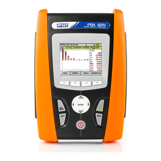
PQA823 - PQA824 - PQA400 4. HOW TO OPERATE 4.1. INSTRUMENT DESCRIPTION CAPTION: 1. Voltage and Current inputs 2. TFT display with “touchscreen” 3. F1 – F4 keys 4. Arrows keys and ENTER key 5. GO/STOP key 6. SAVE key 7. -
Page 11: Keyboard Description
PQA823 - PQA824 - PQA400 4.2. KEYBOARD DESCRIPTION The below keys are available: Key ON/OFF: Press this key to turn on the meter. Press and hold the key for few seconds to turn off the meter. Keys F1, F2, F3, F4: Multifunction keys. The various functions are intended from the s shown on the bottom of display. -
Page 12: Display Description
PQA823 - PQA824 - PQA400 4.3. DISPLAY DESCRIPTION The display is a graphic TFT colour type, 73x57mm sizes (VGA 320x240 pxls) with “touch- screen” which permits a really easy operations using standard PT400 pointer pen fitted in lateral side of meter. -
Page 13: General Menu
PQA823 - PQA824 - PQA400 5. GENERAL MENU Whenever you turn on the meter, the below “Analyzer Configuration” screen is shown, relative to the last configuration used (see Fig. 6): Fig. 6: Example of analyzer configuration In this situation the user can decide whether modify the actual configuration by pressing F1 key (or “CHANGE”... -
Page 14: General Settings
PQA823 - PQA824 - PQA400 5.1. GENERAL SETTINGS Fig. 8: MENU GENERAL screen - General settings section This section permits to set the below control parameters: System language. System Date/Hour. Display brightness. Protection password during recordings. -
Page 15: Date/Time Settings
PQA823 - PQA824 - PQA400 5.1.2. Date/Time settings 1. Press the F1 key (or touch DATE at display) on screen of Fig. 9. The below screen is shown by meter: Fig. 10: Date/Time settings screen 2. Move the cursor using arrows keys on field relative to “Date format” and “Time format”, marked with blue background. -
Page 16: Display Brightness Adjust
PQA823 - PQA824 - PQA400 5.1.3. Display brightness adjust 1. Move the cursor using arrows keys on the field relative to “Brightness”, marked with blue background Fig. 11: Adjust brightness screen 2. Using F3 or F4 keys (alternatively touch MOD(+) o MOD(-)) for adjustment of display brightness percentage. -
Page 17: Sound Keys Setting
PQA823 - PQA824 - PQA400 3. With Password enabled, should GO/STOP key be pressed during a recording, the meter will not stop the operation but will require the user to insert password as shown in the below screen: Fig. 13: Insert Password screen 4. -
Page 18: Auto Power Off Setting
PQA823 - PQA824 - PQA400 5.1.6. Auto power off setting The meter permits to enable or disable the auto power off option in order to prevent a quick discharge of internal battery. This feature, if selected, is active under each of the following conditions: ... -
Page 19: Memory Type Setting
PQA823 - PQA824 - PQA400 5.1.7. Memory type setting The meter permits saving of recordings both in its internal memory (about 15Mbytes) and by using an external compact flash (see § 5.5.4 for details) fitted (see Fig. 3). For the selection of memory type follow the below steps: 1. -
Page 20: Real Time Values
”003” = > Null voltage on the Black and Red wires Frequency Current on L1 phase Current on L2 phase Current on L3 phase Current on Neutral (not avail. for PQA400) Fig. 19: Page of numerical values EN - 18... - Page 21 PQA823 - PQA824 - PQA400 PARAMETERS CAPTION: Total Active Power Pact Total Reactive Power Preact Total Apparent Power Papp Total Power Factor Total Power factor considering fundamental CosPhi of voltage and current signals Fig. 20: Page of total power values PARAMETERS CAPTION: ...
- Page 22 PQA823 - PQA824 - PQA400 PARAMETERS CAPTION: Pst1’ Short term severity after 1 minute Pst Short term severity Pstmax Maximum short term severity Plt Long term severity Pltmax Maximum long term severity Recording Time real time duration of recording expressed in HH:MM Fig.
- Page 23 PQA823 - PQA824 - PQA400 PARAMETERS CAPTION: Average value voltage V1, V2, V3 AVGV Average value current I1, I2, I3 AVGI AVGPact Average value active power on L1, L2, L3 AVGPreact Average value reactive power on L1,L2,L3 Fig.
-
Page 24: Scope Waveforms Screens
Fig. 28: Voltage waveforms screen for 4-wire systems Simultaneous waveforms of currents I1, I2, I3 and neutral current In (for three phase 4- wire system – not available for PQA400), with their TRMS values as shown in below screens: Fig. - Page 25 PQA823 - PQA824 - PQA400 Waveforms of signals on L2 phase, with their TRMS values, as below shown: Fig. 31: Voltage/Current waveforms screen L2 phase for 4-wire systems Waveforms of signals on L3 phase, with their TRMS values, as below shown: Fig.
-
Page 26: Harm Analysis Screens
Harmonics values of V1, V2, V3 voltages and neutral voltage Vn (for three phase 4- wire system – not available for PQA400), currents I1, I2, I3 and neutral current In (for three phase 4-wire system) with THD% values both with histogram graphics and with numerical values in percentage or absolute value, (see §... - Page 27 I1, I2, I3 and neutral current In (for three phase 4-wire system – not available for PQA400) with THD% values both with histogram graphics and with numerical values in percentage or absolute value depending on the desired settings. These values are shown in four pages selectable by pressing cyclically the F1 key (or touch the “PAGE”...
-
Page 28: Vectorial Diagrams Screens
PQA823 - PQA824 - PQA400 Fig. 38: Harmonic analysis of current I1 in percentage/absolute values for 4-wire system 5.2.4. Vectorial diagrams screens Starting from a any page of numerical values it’s possible to select the vectorial diagrams screens of voltage and currents by pressing F4 key (or touch “VECTORS” at display). The aim of this feature is to show, with numerical and graphical indications, the phase angles, expressed in degree [°] between the three voltages V1, V2 and V3 and the currents I1, I2... - Page 29 PQA823 - PQA824 - PQA400 The vectorial diagram of voltage and current for each phase depending on the type of system as shown in below screens: Fig. 41: Vectorial current diagram for 4-wire system Fig. 42: Vectorial voltage/current diagram L1 phase for 4-wire system...
-
Page 30: Analyzer Settings
PQA823 - PQA824 - PQA400 5.3. ANALYZER SETTINGS Fig. 43: Analyzer settings screen Inside this section the meter permits to perform basic and advanced selections relative to the type of electrical installation under test. In particular it is possible to ... - Page 31 PQA823 - PQA824 - PQA400 Fig. 44: Analyzer configuration screen for 4-wire system – ENG type Fig. 45: Analyzer configuration screen for 4-wire system – ENG_UK type Fig. 46: Analyzer Configuration screen for 3-wire system – ENG type Fig. 47: Analyzer Configuration screen for 3-wire system – ENG_UK type...
- Page 32 PQA823 - PQA824 - PQA400 Fig. 48: Analyzer Configuration screen for ARON system – ENG type Fig. 49: Analyzer Configuration screen for ARON system – ENG_UK type Fig. 50: Analyzer Configuration screen for Single phase system – ENG type Fig. 51: Analyzer Configuration screen for Single phase system – ENG_UK type...
- Page 33 PQA823 - PQA824 - PQA400 Fig. 52: Analyzer Configuration screen for Two phase system 3-wire 1Ph3W – ENG type Fig. 53: Analyzer Configuration screen for 2-phase system 3-wire 1Ph3W – ENG_UK type Fig. 54: Analyzer Configuration screen for Two phase system 3-wire 3P 2E – ENG type Fig.
- Page 34 PQA823 - PQA824 - PQA400 Fig. 56: Analyzer Configuration screen for Three phase system 3-wire 3P OD – ENG type Fig. 57: Analyzer Configuration screen for 3-phase system 3-wire 3P OD – ENG_UK type Fig. 58: Analyzer Configuration screen for Three phase system 4-wire 3P HL – ENG type Fig.
-
Page 35: Setting System Frequency
PQA823 - PQA824 - PQA400 Fig. 60: Analyzer Configuration screen for Two phase system 3-wire 3P OY – ENG type Fig. 61: Analyzer Configuration screen for 2-phase system 3-wire 3P OY – ENG_UK type 1. Move the cursor using arrows keys on field relative to “System”, marked with blue background. -
Page 36: Setting Clamp Type
PQA823 - PQA824 - PQA400 5.3.1.2. Setting clamp type This parameter must be always set equal to the clamp type used. Two types of clamps are available: STD: For Standard clamps or Current Transformer. FLEX: For Flexible clamps 1. -
Page 37: Zoom Graphics Option
PQA823 - PQA824 - PQA400 Fig. 62: Advanced Settings screen In the above screen is possible to select advanced options which have effect in Real Time values screens of meter. 5.3.2.1. Zoom graphics option This option permits to select a customized full scale on each phase of voltage and current waveforms (see Fig. -
Page 38: Harmonics Values Option
PQA823 - PQA824 - PQA400 5.3.2.3. Harmonics values option This option permits to select the value of harmonics which can be shown inside Real Time values’ section. 1. Move the cursor using arrows keys on field relative to “Harm. values” , marked it with blue background. -
Page 39: Average Value Option
PQA823 - PQA824 - PQA400 5.3.2.5. Average value option This option, available for 4-wire systems only, permits to display the arithmetic average of TRMS values of: Phase voltages V1, V2, V3. Phase currents I1, I2, I3. Active power on each phase P1, P2, P3. -
Page 40: Recording Settings
PQA823 - PQA824 - PQA400 5.4. RECORDING SETTINGS Fig. 63: Recording Settings screen selection In this section the meter permits to define any detail relative to start and stop of recordings, perform parameters selection for recording, the type of analysis to be carried out very easily thanks to “touch screen”... -
Page 41: Comments
PQA823 - PQA824 - PQA400 The bottom bar of display included the below functions, relative to F1, F2, F3, F4 keys: CLP/EXP: Used to collapse or expand the sub-levels. PREDEF.: Used to open the typical configuration section (see § 5.4.12). -
Page 42: Start And Stop
PQA823 - PQA824 - PQA400 5.4.3. Start and Stop These items permits to define the method to enable and disable the recordings with meter (see § 5.4.13). The possible options are: Manu: Each recording is enabled/disabled in MANUAL mode by pressing GO/STOP key. -
Page 43: General Parameters
PQA823 - PQA824 - PQA400 5.4.6. General Parameters This option permits the selection of network parameters for recording operation. This level included several sub-level for a detailed selection depending on the type of system on test (see § 5.3.1). Depending on the selection performed, different error screen can be shown by meter. - Page 44 PQA823 - PQA824 - PQA400 The opposite situation is the error due to a too many selected parameters. In this case the below screen is shown: Fig. 68: General Parameters section: too many selected parameters In the above screen (see Fig. 68) the harmonics' selection brought about too many selected parameters (more than 251).
-
Page 45: General Parameters: Sub-Levels Description
PQA823 - PQA824 - PQA400 5.4.6.1. General Parameters: sub-levels description Press F1 key (or touch CLP/EXP at display) to expand or compress the sub-levels. The parameters inside sub-levels are strictly depending on type of selected system (see § 5.3.1). As an example, below are shown the screens relative to a three phase 4-wire system. -
Page 46: Harmonics: Sub-Levels Description
PQA823 - PQA824 - PQA400 5.4.6.2. Harmonics: sub-levels description Press F1 key (alternatively touch CLP/EXP at display) to expand or compress the harmonics sub-levels. The parameters inside sub-levels are strictly depending on type of selected system (see § 5.3.1). Below there are some pictures of different possible situations: Fig. -
Page 47: Voltage Anomalies
PQA823 - PQA824 - PQA400 The selection parameters of harmonic analysis require the preliminary selection of voltages or currents inside General Parameter sub-level. The below error screen are shown in these cases: Fig. 72: No selected currents error screen To solve the error (see Fig. 72) situation of above screen select the “Current” inside “General Parameter”... - Page 48 PQA823 - PQA824 - PQA400 Press F4 key (alternatively touch MODIFYat display) for setting the below voltage anomalies parameters: Reference nominal voltage Vref depending on the type of considered system. In particular Vref = VP-N (Single phase and three phase 4-wire systems), Vref = VP-P (three phase 3-wire and ARON systems) ...
-
Page 49: Inrush Current (Only Pqa82X)
PQA823 - PQA824 - PQA400 5.4.8. Inrush current (only PQA82x) This option permits to set the control parameters relative to recording of inrush current events (see § 10.3) which is completely independent from periodic analysis (regulated by integration period). The below screen is shown by meter: Fig. -
Page 50: Flicker (Only Pqa82X)
PQA823 - PQA824 - PQA400 5.4.9. Flicker (only PQA82x) This option permits to set control parameters relative to flicker value recordings on the input voltages in compliance to IEC/EN61000-4-15 standard (see § 10.4). In particular the below parameters are shown by meter: ... -
Page 51: Unbalance
PQA823 - PQA824 - PQA400 Press SAVE or ENTER keys (or the smart icon ) to save each selection and confirm by “Ok” . The main screen of Fig. 63 is shown by meter at the end of the operation. -
Page 52: Predefined Configurations
PQA823 - PQA824 - PQA400 5.4.12. Predefined configurations In order to make the recording start easier the meter includes 5 selectable predefined configurations which describe typical situation in electrical installations, besides a “Default” configuration which defines the initial settings from the factory. The meter also permits to define up to 14 free configuration which can be customized, saved and recalled by user at any time. - Page 53 PQA823 - PQA824 - PQA400 Fig. 84: Typical customized configuration screen In the example of Fig. 84 the typical customized configuration called “GENERIC PLANT” was defined and can be loaded by pressing the SAVE or ENTER keys (or the smart icon ).
- Page 54 PQA823 - PQA824 - PQA400 EN50160 (only PQA82x) GENERAL MENU PARAMETER SETTINGS SYSTEM System Freq[Hz] Analyzer Settings Clamp Type FS Clamp[A] VT Ratio Not modified Each system Zoom Graphics Harm. Type Analyzer Settings - Advanced Harm. Values Zoom 1st Harm.
- Page 55 PQA823 - PQA824 - PQA400 VOLTAGE ANOMALIES GENERAL MENU PARAMETER SETTINGS SYSTEM System Freq[Hz] Analyzer Settings Clamp Type FS Clamp[A] VT Ratio Not modified Each system Zoom Graphics Harm. Type Analyzer Settings - Advanced Harm. Values Zoom 1st Harm. Average Values...
- Page 56 PQA823 - PQA824 - PQA400 HARMONICS GENERAL MENU PARAMETER SETTINGS SYSTEM System Freq[Hz] Analyzer Settings Clamp Type FS Clamp[A] VT Ratio Not modified Each system Zoom Graphics Harm. Type Analyzer Settings - Advanced Harm. Values Zoom 1st Harm. Average Values...
- Page 57 PQA823 - PQA824 - PQA400 INRUSH GENERAL MENU PARAMETER SETTINGS SYSTEM System Freq[Hz] Analyzer Settings Clamp Type FS Clamp[A] VT Ratio Not modified Each system Zoom Graphics Harm. Type Analyzer Settings Harm. Values Advanced Zoom 1st Harm. Average Values Comments...
- Page 58 PQA823 - PQA824 - PQA400 POWER & ENERGY GENERAL MENU PARAMETER SETTINGS SYSTEM System Freq[Hz] Analyzer Settings Clamp Type FS Clamp[A] VT Ratio Not modified Each system Zoom Graphics Harm. Type Analyzer Settings Harm. Values Advanced Zoom 1st Harm. Average Values Comments POWER &...
- Page 59 PQA823 - PQA824 - PQA400 DEFAULT CONFIGURATION GENERAL MENU PARAMETER SETTINGS System 4-wire Freq[Hz] Analyzer Settings Clamp Type FLEX FS Clamp[A] 3000 VT Ratio Zoom Graphics AUTO Harm. Type Analyzer Settings Harm. Values ABSOLUTES Advanced Zoom 1st Harm. Average Values...
-
Page 60: Start A Recording
PQA823 - PQA824 - PQA400 5.4.13. Start a recording The meter is designed to start a recording in MANUAL or AUTOMATIC mode (see § 5.4.3) by pressing of GO/STOP key. A recording operation can be started exclusively under the following screens: ... - Page 61 PQA823 - PQA824 - PQA400 CAUTION For recordings ALWAYS use the external power supply even though the instrument allows the operator to perform a recording using internal batteries. After starting a recording a preliminary real time evaluation about the situation on electrical installation it’s important in order to perform a correct settings, using the predefined...
-
Page 62: Automatic Start Of Recording
PQA823 - PQA824 - PQA400 Depending on the type and number of errors, the necessary modifications of setting parameters should be performed. Press GO/STOP key again to start recording and verify the possible residual error on window message. Confirm with ENTER or press “Ok” or “Cancel” keys to close the warning window message and start the recording by pressing GO/STOP key anyway. -
Page 63: During A Recording
PQA823 - PQA824 - PQA400 5.4.14. During a recording After a recording is running, a real time check of parameters’s values and internal status is shown by meter. Fig. 92: Recording Results screen - Recording running 1. Select “Recording Results” in GENERAL MENU. - Page 64 PQA823 - PQA824 - PQA400 Each recording running is stopped and results are automatically saved by meter by pressing of GO/STOP key or as soon as the date/hour of automatic stop is reached. CAUTION The only “Real Time Values” section is available during a recording running.
-
Page 65: Saved Data Management Section
PQA823 - PQA824 - PQA400 5.5. SAVED DATA MANAGEMENT SECTION Fig. 94: GENERAL MENU - Saved Data Management The “Saved Data Management” section allows the user to check the content of the internal memory after recording, to delete previous recordings and possibly to copy a recording (one at a time) on an external USB Pen Driver connected to the instrument. -
Page 66: Recording Analysis (Reg Type)
PQA823 - PQA824 - PQA400 5.5.1. Recording analysis (Reg type) This page shows the analyses which can be performed on the saved data (Reg type). Fig. 96: Recording analysis (Reg-type data) 1. Use the up and down arrow keys to highlight on blue background one of the analyses on the screen. -
Page 67: Recording Graph
PQA823 - PQA824 - PQA400 5.5.1.2. Recording graph By selecting the recording graph option, the following page is accessed, which enables the user to display the recording trend (ONLY ONE parameter at a time). Fig. 98: Selecting a parameter 1. Press the F1 key (or the PARAM item on the display) to access the page containing the recorded quantities available for the analysis (Fig. - Page 68 PQA823 - PQA824 - PQA400 This page shows the graph, the cursor position (cursor T) and the maximum, minimum and average RMS values of the parameter selected by the cursor. Fig. 100: Recording graph The following keys are active on this page: ...
-
Page 69: Dips Ans Swells
PQA823 - PQA824 - PQA400 Example of advanced graph. Let us take a recording of 2000 pixels into consideration. The PQA has a display with a useful resolution of about 200 pixels; therefore, it is not able to distinctly display all the pixels in our recording. -
Page 70: Fast Transient
PQA823 - PQA824 - PQA400 This page shows the parameters set before recording voltage anomalies: Fig. 103: Voltage Anomalies The following non-modifiable parameters are indicated (as they have been set upon starting the recording). Nominal Voltage: Nominal voltage. High Voltage: Limit high voltage. - Page 71 PQA823 - PQA824 - PQA400 Column description: Progressive number of the transient. Phase in which the transient occurred. Date/Time: Date/time at which the anomaly occurred. Peak+: Max. positive value reached by the transient during the observation interval. Peak-: Min. negative value reached by the transient during the observation interval.
-
Page 72: Inrush Currents
PQA823 - PQA824 - PQA400 5.5.1.5. Inrush currents This page shows a table containing all inrush currents occurred during recording. Fig. 106: Inrush currents Column description: Progressive number of the inrush current. Phase in which the inrush current occurred. Date/Time: Date/time at which the inrush current occurred. - Page 73 PQA823 - PQA824 - PQA400 The following data are indicated: Type: Type of measurement set: Fix: The instrument has detected and saved an event when the current's RMS value, calculated in each half-period, exceeded the value of the threshold defined by the user.
-
Page 74: En50160
PQA823 - PQA824 - PQA400 5.5.1.6. EN50160 This page shows a table containing all values according to standard CEI EN50160. Fig. 109: EN50160 analysis result Column description: Param: The percentages of the values are indicated, which must be within the limits set in Limits. - Page 75 PQA823 - PQA824 - PQA400 The following data are indicated: Nominal Voltage: Set nominal voltage. High Voltage: Limit high voltage. Low Voltage: Limit low voltage. Frequency: System frequency. This page also shows the total number of voltage anomalies occurred (Number of Anomalies).
-
Page 76: Analysis Of Consumed Energy
PQA823 - PQA824 - PQA400 5.5.1.7. Analysis of consumed energy This page shows the Energy and Peak power values consumed while recording Fig. 112: Screen of total consumed energy Description of the displayed values: Eact: Total active power consumed while Recording. -
Page 77: Analysis Of Producted Energy
PQA823 - PQA824 - PQA400 5.5.1.8. Analysis of producted energy This page shows the Energy and Peak power values producted while recording Fig. 113: Screen of total producted energy Description of the displayed values: Eact: Total active power produced while Recording. -
Page 78: Recording Analysis (Istant Type)
PQA823 - PQA824 - PQA400 5.5.2. Recording analysis (Istant type) This page shows the analyses which can be performed on the saved data (Istant type). Fig. 114: Recording analysis (Istant-type data) 1. Use the up and down arrow keys to highlight on blue background one of the analyses on the screen. -
Page 79: Graph
PQA823 - PQA824 - PQA400 5.5.2.2. Graph This screen (Fig. 116) contemporarily shows the saved instant values of the waveforms of voltages V1, V2, V3, Vn scaled according to the Full scale (Fs) and the relevant RMS values; these values have been saved by the instrument upon pressing the SAVE key. -
Page 80: Vectors
PQA823 - PQA824 - PQA400 In the upper half plane of the graph if the harmonics are introduced into the relevant electrical system from the mains. In the lower half plane of the graph if the harmonics are injected into the relevant electrical system from the mains. -
Page 81: Measures
PQA823 - PQA824 - PQA400 5.5.2.5. Measures As an example, below are shown the screens relative to a three phase 4-wire system. Similar consideration can be applied to any other selected system. In measure mode, the instrument displays the saved values in TRMS as shown in the following figures: In this page, the following symbols are used: V1N ... -
Page 82: Transfer Recordings To A External Pen Driver Usb
PQA823 - PQA824 - PQA400 5.5.3. Transfer recordings to a external Pen Driver USB The meter permits to transfer of one or more saved recordings which are shown in Fig. 95 to a external Pen Driver USB directly connected to it (see Fig. 3). The below picture is shown by meter: Fig. -
Page 83: Saving Recordings To External Compact Flash (Only Pqa82X)
PQA823 - PQA824 - PQA400 5.5.4. Saving recordings to external Compact Flash (only PQA82x) The PQA82x meter permits to save the recordings also on external standard compact flash which are fitted on suitable input (see Fig. 3) after activating “EXTERNAL” option on Memory type (see §... -
Page 84: Meter Information
METER INFORMATION Inside this section the general internal parameters of meter are available as information from the user for example during any contact with Service people of HT ITALIA. Fig. 125: Menu General screen – Meter information section Press ENTER key or touch the correspondent icon at display. The below screen is shown by meter: Fig. -
Page 85: Connection Of Meter To Pc (With Win Xp)
Select “PQA823”, “PQA824” or “PQA400” model from the available list of meters only for the first connection. 6. Select the “Download data” command and pressing “Next” key in order to open the “Download”... -
Page 86: Measuring Procedures
PQA823 - PQA824 - PQA400 7. MEASURING PROCEDURES 7.1. USING OF METER IN A SINGLE PHASE SYSTEM – ENG TYPE CAUTION The maximum voltage among B1, B2, B3, B4 and BE inputs is 1000V / CAT IV 600V to ground. Do not measure voltages exceeding the limits prescribed by this manual. -
Page 87: Using Of Meter In A Single Phase System - Eng_Uk Type
PQA823 - PQA824 - PQA400 7.2. USING OF METER IN A SINGLE PHASE SYSTEM – ENG_UK TYPE CAUTION The maximum voltage among B1, B2, B3, B4 and BE inputs is 1000V / CAT IV 600V to ground. Do not measure voltages exceeding the limits prescribed by this manual. -
Page 88: Using Of Meter In A 3-Phase 4 Wire System - Eng Type
PQA823 - PQA824 - PQA400 7.3. USING OF METER IN A 3-PHASE 4 WIRE SYSTEM – ENG TYPE CAUTION The maximum voltage among B1, B2, B3, B4 and BE inputs is 1000V / CAT IV 600V to ground. Do not measure voltages exceeding the limits prescribed by this manual. -
Page 89: Using Of Meter In A 3-Phase 4 Wire System - Eng_Uk Type
PQA823 - PQA824 - PQA400 7.4. USING OF METER IN A 3-PHASE 4 WIRE SYSTEM – ENG_UK TYPE CAUTION The maximum voltage among B1, B2, B3, B4 and BE inputs is 1000V / CAT IV 600V to ground. Do not measure voltages exceeding the limits prescribed by this manual. -
Page 90: Using Of Meter In A Three Phase 3 Wire System - Eng Type
PQA823 - PQA824 - PQA400 7.5. USING OF METER IN A THREE PHASE 3 WIRE SYSTEM – ENG TYPE CAUTION The maximum voltage among B1, B2, B3, B4 and BE inputs is 1000V / CAT IV 600V to ground. Do not measure voltages exceeding the limits prescribed by this manual. -
Page 91: Using Of Meter In A Three Phase 3 Wire System - Eng_Uk Type
PQA823 - PQA824 - PQA400 7.6. USING OF METER IN A THREE PHASE 3 WIRE SYSTEM – ENG_UK TYPE CAUTION The maximum voltage among B1, B2, B3, B4 and BE inputs is 1000V / CAT IV 600V to ground. Do not measure voltages exceeding the limits prescribed by this manual. -
Page 92: Using Of Meter In A Three Phase 3 Wire Aron System - Eng Type
PQA823 - PQA824 - PQA400 7.7. USING OF METER IN A THREE PHASE 3 WIRE ARON SYSTEM – ENG TYPE CAUTION The maximum voltage among B1, B2, B3, B4 and BE inputs is 1000V / CAT IV 600V to ground. Do not measure voltages exceeding the limits prescribed by this manual. -
Page 93: Using Of Meter In A 3-Phase 3 Wire Aron System - Eng_Uk Type
PQA823 - PQA824 - PQA400 7.8. USING OF METER IN A 3-PHASE 3 WIRE ARON SYSTEM – ENG_UK TYPE CAUTION The maximum voltage among B1, B2, B3, B4 and BE inputs is 1000V / CAT IV 600V to ground. Do not measure voltages exceeding the limits prescribed by this manual. -
Page 94: Using Of Meter In A 3-Phase 4-Wire 3Phl (Usa System) - Eng Type
PQA823 - PQA824 - PQA400 7.9. USING OF METER IN A 3-PHASE 4-WIRE 3PHL (USA SYSTEM) – ENG TYPE CAUTION The maximum voltage among B1, B2, B3, B4 and BE inputs is 1000V / CAT IV 600V to ground. Do not measure voltages exceeding the limits prescribed by this manual. -
Page 95: Using In A 3-Phase 4-Wire 3Phl (Usa System) - Eng_Uk Type
PQA823 - PQA824 - PQA400 7.10. USING IN A 3-PHASE 4-WIRE 3PHL (USA SYSTEM) – ENG_UK TYPE CAUTION The maximum voltage among B1, B2, B3, B4 and BE inputs is 1000V / CAT IV 600V to ground. Do not measure voltages exceeding the limits prescribed by this manual. -
Page 96: Using Of Meter In A 3-Phase 3-Wire 3Pod (Usa System) - Eng Type
PQA823 - PQA824 - PQA400 7.11. USING OF METER IN A 3-PHASE 3-WIRE 3POD (USA SYSTEM) – ENG TYPE CAUTION The maximum voltage among B1, B2, B3, B4 and BE inputs is 1000V / CAT IV 600V to ground. Do not measure voltages exceeding the limits prescribed by this manual. -
Page 97: Using Of Meter In 3-Phase 3-Wire 3Pod (Usa System) - Eng_Uk Type
PQA823 - PQA824 - PQA400 7.12. USING OF METER IN 3-PHASE 3-WIRE 3POD (USA SYSTEM) – ENG_UK TYPE CAUTION The maximum voltage among B1, B2, B3, B4 and BE inputs is 1000V / CAT IV 600V to ground. Do not measure voltages exceeding the limits prescribed by this manual. -
Page 98: Using Of Meter In A 3 Wire 3P2E (Usa System) - Eng Type
PQA823 - PQA824 - PQA400 7.13. USING OF METER IN A 3 WIRE 3P2E (USA SYSTEM) – ENG TYPE CAUTION The maximum voltage among B1, B2, B3, B4 and BE inputs is 1000V / CAT IV 600V to ground. Do not measure voltages exceeding the limits prescribed by this manual. -
Page 99: Using Of Meter In A 3 Wire 3P2E (Usa System) - Eng_Uk Type
PQA823 - PQA824 - PQA400 7.14. USING OF METER IN A 3 WIRE 3P2E (USA SYSTEM) – ENG_UK TYPE CAUTION The maximum voltage among B1, B2, B3, B4 and BE inputs is 1000V / CAT IV 600V to ground. Do not measure voltages exceeding the limits prescribed by this manual. -
Page 100: Using Of Meter In A 3 Wire 3Poy (Usa System) - Eng Type
PQA823 - PQA824 - PQA400 7.15. USING OF METER IN A 3 WIRE 3POY (USA SYSTEM) – ENG TYPE CAUTION The maximum voltage among B1, B2, B3, B4 and BE inputs is 1000V / CAT IV 600V to ground. Do not measure voltages exceeding the limits prescribed by this manual. -
Page 101: Using Of Meter In A 3 Wire 3Poy (Usa System) - Eng_Uk Type
PQA823 - PQA824 - PQA400 7.16. USING OF METER IN A 3 WIRE 3POY (USA SYSTEM) – ENG_UK TYPE CAUTION The maximum voltage among B1, B2, B3, B4 and BE inputs is 1000V / CAT IV 600V to ground. Do not measure voltages exceeding the limits prescribed by this manual. -
Page 102: Using Of Meter In A 3 Wire 1Ph3W (Usa System) - Eng Type
PQA823 - PQA824 - PQA400 7.17. USING OF METER IN A 3 WIRE 1PH3W (USA SYSTEM) – ENG TYPE CAUTION The maximum voltage among B1, B2, B3, B4 and BE inputs is 1000V / CAT IV 600V to ground. Do not measure voltages exceeding the limits prescribed by this manual. -
Page 103: Using Of Meter In A 3 Wire 1Ph3W (Usa System) - Eng_Uk Type
PQA823 - PQA824 - PQA400 7.18. USING OF METER IN A 3 WIRE 1PH3W (USA SYSTEM) – ENG_UK TYPE CAUTION The maximum voltage among B1, B2, B3, B4 and BE inputs is 1000V / CAT IV 600V to ground. Do not measure voltages exceeding the limits prescribed by this manual. -
Page 104: Maintenance
8.1. GENERAL The PQA82x and PQA400 are precision meters. For their use and storage, follow the recommendations and instructions of this manual in order to avoid possible damages or dangers. Never use the instrument in environments with a high humidity or temperature. -
Page 105: Technical Specifications
PQA823 - PQA824 - PQA400 9. TECHNICAL SPECIFICATIONS 9.1. TECHNICAL FEATURES TRMS AC/DC Voltage Phase-Neutral / Phase-Ground – Single phase / Three phase systems Range Accuracy Resolution Input impedance 0.0 600.0V (0.5%rdg+2dgt) 0.1V 10M Max crest factor = 2 Voltage values <... - Page 106 PQA823 - PQA824 - PQA400 Inrush Current (only PQA82x) Time resolution Time accuracy Range Accuracy Resolution (50Hz) (50Hz) Depending on Depending on (1.0%rdg+0.4%FS) 10ms 10ms clamp type clamp type Max crest factor = 3 Maximum number of recorded events: 1000 Power –...
-
Page 107: General Features
PQA823 - PQA824 - PQA400 9.2. GENERAL FEATURES Real time values General network parameters: Voltages, Currents, Powers, Cos Flicker, Unbalance, THD%, Harmonics Signals waveforms: Voltages, Currents, harmonics histograms Vectorial diagrams: Voltages, Currents Recordings Parameters: Each general parameters + energies Number of selectable parameter:... -
Page 108: Appendix - Theoretical Outlines
PQA823 - PQA824 - PQA400 APPENDIX – THEORETICAL OUTLINES 10.1. VOLTAGE ANOMALIES The meter is capable of recording all those TRMS values as voltage anomalies, calculated every 10ms, beyond the percentage thresholds of Voltage Reference (Vref) set during the programming from ±1% to ±30% with steps of 1%. These limits remain unchanged throughout the recording period. -
Page 109: Limit Values For Harmonic Voltage
PQA823 - PQA824 - PQA400 LEGEND: 1. Fundamental 2. Third Harmonic 3. Distorted Waveform Effect of the sum of 2 multiple frequencies The EN50160 standard recommends to stop the index in the expression (1) corresponding to the 40 harmonic. A fundamental element to detect the presence of harmonics is THD defined as: ... -
Page 110: Presence Of Harmonics: Causes
PQA823 - PQA824 - PQA400 10.2.3. Presence of harmonics: causes Any apparatus that alters the sine wave or uses only a part of such a wave causes distortions to the sine wave and therefore harmonics. All current signals result in some way virtually distorted. The most common situation is the harmonic distortion caused by no-linear loads such as electric household appliances, personal computers or speed control units for motors. -
Page 111: Inrush Currents (Only Pqa82X)
PQA823 - PQA824 - PQA400 10.3. INRUSH CURRENTS (ONLY PQA82X) The PQA82x meters permits the real time detection of inrush current events, typical of start-up of electrical machines and also for other industrial applications (e.g. troubleshooting problem regarding loads switching, correct calculation of protection devices, oscillating currents, etc…) as shown in the following pictures:... -
Page 112: Flicker
PQA823 - PQA824 - PQA400 Detectable modes : The below modes are available and selectable: FIX: The meter detect and recording a event each time the TRMS value of current, calculated on each half period (10ms @ 50Hz, 8.3ms @ 60Hz), it’s over the limit threshold defined by user. -
Page 113: Supply Voltage Unbalance
PQA823 - PQA824 - PQA400 10.5. SUPPLY VOLTAGE UNBALANCE In normal conditions the supply voltage and the final loads are perfectly balanced. Unbalances are possible in trouble situations (low insulation) and/or phase circuits interruptions. Moreover, in single phase systems, the balance can be only statistic. -
Page 114: Voltage Fast Transients (Spikes) (Only Pqa824)
PQA823 - PQA824 - PQA400 10.6. VOLTAGE FAST TRANSIENTS (SPIKES) (ONLY PQA824) The meter considers all the phenomena associated to the phase voltage as voltage spikes which have the following properties: Fast slope variations of voltage waveforms. Exceeding a limit threshold fixed by user before starting a recording. - Page 115 PQA823 - PQA824 - PQA400 and that during the detectable time interval defined as: 32 x 5s = 160s. 32 x 78s = 2.5ms. 32 x 65s = 2.1ms. the positive and negative difference (defined DELTA+ and DELTA- respectively) it’s over the “windows”...
-
Page 116: Power And Power Factor: Definitions
PQA823 - PQA824 - PQA400 10.7. POWER AND POWER FACTOR: DEFINITIONS In a standard electrical installation powered by three sine voltages the following are to be defined: cos( Phase Active Power: (n=1,2,3) actn Phase Apparent Power:... -
Page 117: Conventions On Powers And Power Factors
PQA823 - PQA824 - PQA400 It shall be noted that the expression of the phase Reactive Power with no sine waveforms, would be wrong. To understand this, it may be useful to consider that both the presence of harmonics and the presence of reactive power produce, among other effects, an increase of line power losses due to the increased current RMS value. -
Page 118: Three Phase 3 Wire Aron System
PQA823 - PQA824 - PQA400 The active power (positive or negative) is defined in the panel and therefore acquires the value Pact of the active power in that moment. The reactive power (inductive or capacitive, positive or negative) is defined in the panel and Preact therefore acquires the value of the reactive power in that moment. -
Page 119: Measuring Method: Outlines
PQA823 - PQA824 - PQA400 10.8. MEASURING METHOD: OUTLINES The meter is capable of measuring: voltages, currents, active powers, inductive and capacitive reactive powers, apparent powers, inductive and capacitive power factors, energies, analogical or pulse parameters. All these parameters are analysed in a digital way for each phase (voltage and current) and calculated based on formulas of the previous sections. -
Page 120: After-Sale Service
PQA823 - PQA824 - PQA400 AFTER-SALE SERVICE 11.1. WARRANTY This instrument is guaranteed against any defects in material and manufacturing, in compliance with the general sale terms and conditions. During the warranty period all defective parts may be replaced, but the manufacturer reserves the right to repair or replace the product. - Page 124 Fax: +55 19 9979.11325 eMail: info@htinstruments.es eMail: ht@htitalia.it eMail: vendas@ht-instruments.com.br Web: www.htinstruments.es Web: www.ht-instruments.com Web: www.ht-instruments.com.br HT INSTRUMENTS USA LLC HT INSTRUMENTS GMBH HT ITALIA CHINA OFFICE 3145 Bordentown Avenue W3 Am Waldfriedhof 1b 意大利HT中国办事处 08859 Parlin - NJ - USA...
Need help?
Do you have a question about the PQA400 and is the answer not in the manual?
Questions and answers