Siemens FIDAMAT 6 Operating Instructions Manual
Gas analyzer for the measurement of total hydrocarbons
Hide thumbs
Also See for FIDAMAT 6:
- Operating instructions manual (180 pages) ,
- Operating instructions manual (202 pages) ,
- Compact operating instructions (37 pages)

Related Manuals for Siemens FIDAMAT 6


Summary of Contents for Siemens FIDAMAT 6
- Page 1 Operating Instructions Edition 08/2004 gas analysis FIDAMAT 6 Gas analyzer for the measurement of total hydrocarbons 7MB2421...
-
Page 3: Operating Instructions
FIDAMAT 6 Gas analyzer for the measurement of total hydrocarbons Operating instructions A5E00222135-01 Release 08/2004... - Page 4 Conformemente alla "Legge sulle unità di misura" i dati in pollici valgono soltanto per l'esportazione. SIEMENS AG Automation and Drives Process Instrumentation © Siemens AG 2004 Subject to modifications without prior notice D-76181 Karlsruhe Siemens Aktiengesellschaft Order no. A5E00222135 Printed in Germany...
-
Page 5: Table Of Contents
Table of contents ..................... 1-1 NFORMATION FOR THE OWNER ..................... 1-2 NFORMATION FOR OUR CUSTOMERS ........................1-2 ENERAL COMMENTS ........................1-3 SING THIS MANUAL ......................... 1-3 AZARD INFORMATION ....................1-4 SE FOR THE PURPOSE INTENDED ........................ 1-5 UALIFIED PERSONNEL ......................1-5 ARRANTY INFORMATION ....................... - Page 6 ..........................6-1 AINTENANCE ......................6-2 AINTENANCE CONCEPT 6.1.1 ........................ 6-2 UMP MAINTENANCE 6.1.2 ....................6-2 EPLACING THE FILTER PLATE ..............6-3 EPLACING THE MOTHERBOARD AND OPTION BOARD ........................6-3 HANGING FUSES ........................6-4 LEANING THE UNIT ................6-4 AINTENANCE REQUEST AND FAULT MESSAGE 6.5.1 ....................
-
Page 7: Information For The Owner
Information for the owner 1.1. Information for our customers 1.2. General comments 1.3. Using this manual 1.4. Hazard information 1.5. Use for the purpose intended 1.6. Qualified personnel 1.7. Warranty information 1.8. Delivery information 1.9. Standards and regulations 1.10. Declaration of conformity... -
Page 8: Information For Our Customers
If you require further information, or should problems be encountered which are not treated in sufficient depth in this document, contact your local Siemens representative for the information you require. Note Particularly before the device is used for new applications in the area of research and development, we recommend you contact us to discuss the application in question. -
Page 9: Using This Manual
Caution without a warning triangle means that damage to property may result if the corresponding precautions are not taken. FIDAMAT 6 gas analyzer Operating manual – A5E00222135-01... -
Page 10: Use For The Purpose Intended
(in this regard see also "Technical description” from page 2-1 onwards) and only in conjunction with third-party devices and components recommended or approved by Siemens. The product described in this manual has been designed, manufactured, inspected and documented in compliance with the relevant safety standards. -
Page 11: Qualified Personnel
The contents of this product documentation do not constitute part of a past or existing agreement, promise, or legal relationship nor are they intended to modify these. All obligations on the part of Siemens originate from the purchase contract in question, which also includes the full and exclusively valid warranty provisions. -
Page 12: Delivery Information
Federal Republic of Germany will apply (see also "Technical data” on page 2-14). If this product is used outside the area of validity of these standards and regulations, the standards and regulations valid in the owner's country should be observed. FIDAMAT 6 gas analyzer Operating manual – A5E00222135-01... -
Page 13: Declaration Of Conformity
Siemens Aktiengesellschaft Automation and Drives A&D PI 2 D-76181 Karlsruhe If this product is used outside the European Union, the standards and regulations valid in the owner's country must be observed. FIDAMAT 6 gas analyzer Operating manual – A5E00222135-01... - Page 14 Information for the owner FIDAMAT 6 gas analyzer Operating manual – A5E00222135-01...
-
Page 15: Technical Description
Technical description 2.1. Scope of application 2.2. Design 2.3. Mode of operation 2.4. Communications 2.5. Technical data... - Page 16 Examples of applications • Environmental protection • Wastewater (in combination with a The FIDAMAT 6 gas analyzer is used for the stripping unit, determination of quantitative determination of hydrocarbons. The hydrocarbon content of liquids) analyzer is also suitable for measurements in •...
- Page 17 OXYMAT 6, ULTRAMAT 6, OXYMAT 61) own authorization code to prevent inadvertent or unauthorized operator • Customer-specific versions of the device, actions such as: - Customer acceptance - TAG plates - Drift recording FIDAMAT 6 gas analyzer Operating manual –A5E00222135-01...
-
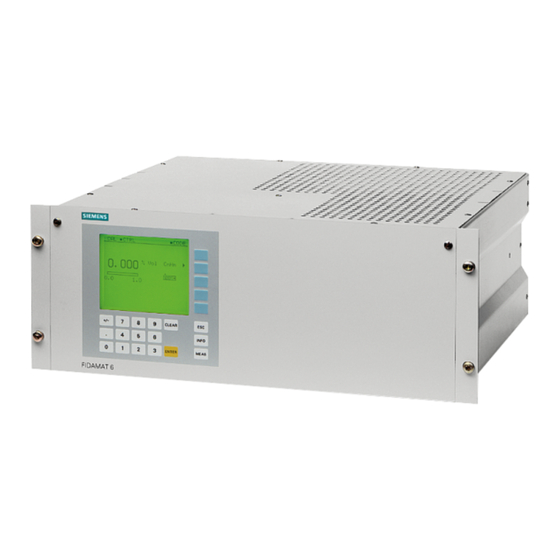
Page 18: Design
Design Design of the FIDAMAT 6 housing Design of the overall unit • 19" rack module with 4 HU for installation The FIDAMAT 6 consists of two main modules. in swing frame Analysis module b) Electronics • 19" rack module with 4 HU for installation... -
Page 19: Communications
Trichloroethene 1,01 four calibration gases Tetrachloroethene 1,07 Chloroform 0,72 Communications Chlorobenzene 1,15 • ELAN (RS 485) contained in base unit (connection at rear) FIDAMAT 6 gas analyzer Operating manual –A5E00222135-01... - Page 20 Technical description Fig. 2-1: Membrane keyboard and graphics display Fig. 2-1: Membrane keyboard and graphics display FIDAMAT 6 gas analyzer Operating manual –A5E00222135-01...
-
Page 21: M Ode Of Operation
The reading deviation for the molecule in question is expressed by the response factor. The measuring gas is supplied to the FIDAMAT 6 under overpressure or drawn in by the built-in diaphragm pump (optionally via a heated line and an additional filter) and then routed to the flame ionization detector via a non-clogging fused-silica restrictor. - Page 22 After switching on the analyzer, the flame will be ignited as soon as a flame temperature of 165°C has been reached. The pump is started automatically once the flame reaches a temperature of 220°C. The FIDAMAT 6 sends out various signals in the form of floating contacts: • Maintenance request...
- Page 23 Technical description Fig. 2-3: Gas circuit (unit with pump) FIDAMAT 6 gas analyzer Operating manual – A5E00222135-01...
- Page 24 All of the gas analyzers in Series 6, ULTRAMAT RS-485 / RS-232 converter with 6, OXYMAT 6/ 61, CALOMAT 6, ULTRAMAT 23 RS 485 and RS 232 connecting leads and also FIDAMAT 6 provide the following RS 485 bus plug with jumper communication methods: Analyzer RS 485 cable •...
- Page 25 PROFIBUS DP / PA • Downloading of new software PROFIBUS DP / PA is the field-bus market leader. All Siemens gas analyzers when equipped with an Hardware requirements: optional plug-in board (can be retrofitted) have Profibus capability and meet the mandatory "device •...
- Page 26 – 6, OXYMAT 6/ 61, CALOMAT 6, ULTRAMAT 6 what is known as "interoperability”. At the end of and FIDAMAT 6 and also ULTRAMAT 23) have 1999 a mandatory profile for analysis devices PROFIBUS capability once fitted with an optional...
- Page 27 Order number: C79000-B5200-C188 German C79000-B5276-C188 English Fig. 2-6: Basic structure of an AK interface FIDAMAT 6 gas analyzer 2-13 Operating manual –A5E00222135-01...
-
Page 28: Technical Data
< 1% of measuring span concerned Electrical safety To EN 61010-1, Linearity deviation < 1% of measuring span concerned overvoltage category II Fuse-protection values 100... 120 V: 4.0 T/ 250 200... 240 V: 2.5 T/ 250 FIDAMAT 6 gas analyzer 2-14 Operating manual – A5E00222135-01... -
Page 29: Climatic Conditions
420 ± 20 ~ 320 ~ 500 Sample atmosphere 500 ± 2 ~ 1000 Zero gas 2.500 – 3.000 500 ± 2 ~ 1000 Turning gas 2.500 – 3.000 500 ± 2 ~ 1000 FIDAMAT 6 gas analyzer 2-15 Operating manual –A5E00222135-01... - Page 30 2-16 FIDAMAT 6 gas analyzer Operating manual – A5E00222135-01...
-
Page 31: Installation Instructions
Installation instructions Installation instructions 3.1. Safety instructions 3.2. General installation requirements 3.3. Gas conditioning 3.4. Electrical connections 3.4.1. Power supply 3.4.2. Connecting the signal lines 3.4.3. Circuit diagrams (electrical connections) 3.4.3.1. Pin assignments on the motherboard (default) 3.4.3.2. Pin assignments on the optional plug-in board and PROFIBUS 3.4.3.3. - Page 32 In accordance with details in the technical data starting on page2-14, there may be what is to be regarded as a limited escape of flammable components from leaks in the sample path. With the FIDAMAT 6 there is no need to flush the housing provided it has been ensured that there is a natural exchange of air from the environment.
- Page 33 You should also ensure that the unit is not exposed to direct sun light. If the FIDAMAT 6 is installed in a cabinet or desktop casing, it must be accommodated on support or telescopic rails. It can also be fitted into a swing frame.
- Page 34 To to install a siphon as a water trap. this end, it is advisable Fig. 3-1: FIDAMAT 6, gas and electrical connections FIDAMAT 6 gas analyzer Operating manual –A5E00222135-01...
-
Page 35: Gas Conditioning
(= combustion air pressure) and the hydrogen pressure. Maintenance Both the electrical safety and the serviceability of all unit components must be checked regularly. For this reason the FIDAMAT 6 needs an annual servicing. The servicing frequency can be reduced in individual cases on the basis of the owner's judgment if no negative effects on the sample-wetted seals are to be expected from chemical attack. -
Page 36: Electrical Connections
Due to the heat radiation a minimum distance of one inch from the housing must be observed when wiring the device. 3.4.2 Connecting the signal lines Warning Signal lines should only be connected to units which are safely electrically isolated from their auxiliary power. FIDAMAT 6 gas analyzer Operating manual –A5E00222135-01... - Page 37 Installation instructions • With the FIDAMAT 6 the signal lines are connected to the SUB D connectors at the rear of the unit. • The connection cables to the relay outputs, the binary inputs and the analog inputs and outputs must be shielded. They should be connected to the corresponding trapezoidal plug (SUB-D plug) as shown in the allocation lists (see "Pin assignments”...
-
Page 38: Circuit Diagrams (Electrical Connections)
Installation instructions 3.4.3 Circuit diagrams (electrical connections) 3.4.3.1 Pin assignments on the motherboard (default) Fig. 3-2: FIDAMAT 6, 19" rack module, pin assignments FIDAMAT 6 gas analyzer Operating manual –A5E00222135-01... - Page 39 Installation instructions 3.4.3.2 Pin assignments on the optional plug-in board and PROFIBUS Fig. 3-3: FIDAMAT 6, 19" rack module, pin assignments of AUTOCAL board and PROFIBUS connector FIDAMAT 6 gas analyzer Operating manual – A5E00222135-01...
- Page 40 For further information see function 73 in "ELAN configuration” on page 5-33 or in the description of the ELAN interface. Order number: C79000-B5200-C176 German C79000-B5276-C176 English Fig. 3-4: Pin assignments FIDAMAT 6 gas analyzer 3-10 Operating manual –A5E00222135-01...
-
Page 41: Dimension Drawings
Installation instructions Dimension drawings Fig. 3-5: Dimension drawing of the FIDAMAT 6 (dimensions in mm) FIDAMAT 6 gas analyzer Operating manual – A5E00222135-01 3-11... - Page 42 Installation instructions FIDAMAT 6 gas analyzer 3-12 Operating manual –A5E00222135-01...
-
Page 43: Start-Up
Start-up Start-up 4.1. Safety instructions 4.2. Start-up preparations 4.3. Start-up and operation 4.3.1. Measuring ranges 4.3.2. Calibration... - Page 44 In accordance with details in the technical data, there may be what is to be regarded as a limited escape of flammable components from leaks in the sample path. With the FIDAMAT 6 there is no need to flush the housing provided it has been ensured that there is a natural exchange of air from the environment.
- Page 45 Start-up Start-up preparations Position of unit The FIDAMAT 6 may only be operated in a vertical position. Gas conditioning Gas preparation takes place via a heated sample gas filter (approx. 200°C) with a pore size of 3 µm and with a very limited capacity.
-
Page 46: Operation
(see also "Technical data” on page 2-14). Pressure influence If measurement is carried out externally, the unit will carry out an automatic pressure correction. If there are pressure fluctuations within the unit, pressure compensation will be carried out automatically. FIDAMAT 6 gas analyzer Operating manual –A5E00222135-01... - Page 47 Above this, on the top line, is the status display (Section 5.1). Warming up With the FIDAMAT 6 it is necessary to wait for about one hour for the warming-up phase to finish. During this time, the oven heats up to 200°C (accessible via function 2 "Diagnostics values”).
- Page 48 Dropping below the smallest measuring range (according to the nameplate) is not permitted as in this case noise and the influence of temperature on the measured value would increase relative to the measuring range and reproducibility and drift behavior would deteriorate. FIDAMAT 6 gas analyzer Operating manual –A5E00222135-01...
- Page 49 0 – 20 ppm values Zero point: 0 ppm Note input pressures Inputting setpoint value Recommended: for zero points and span (see "Technical data” on page 2-14) 15 ppm Calibration of zero point Span calibration FIDAMAT 6 gas analyzer Operating manual – A5E00222135-01...
- Page 50 Recom.: 30 ppm C Calibration of zero point Span calibration A detailed description of operator and input possibilities for the above- mentioned functions may be found in Chapter 5 "Operation” starting on page 5-1. FIDAMAT 6 gas analyzer Operating manual –A5E00222135-01...
-
Page 51: General Comments
Operation 5.1. General comments 5.2. Overview of operator functions 5.2.1. Diagnosis 5.2.2. Calibration 5.2.3. Measuring ranges 5.2.4. Parameters 5.2.5. Configuration... - Page 52 Operation General comments Fig. 5-1: Display and control panel FIDAMAT 6 gas analyzer Operating manual –A5E00222135-01...
- Page 53 Graphic symbols Switching function (ON state) □ Switching function (OFF state; also status display on the status line) ► Entry into a subsequent menu ● Initiation of a function (for example, Start calibration…) FIDAMAT 6 gas analyzer Operating manual –A5E00222135-01...
- Page 54 Operation Fig. 5-2: Display and operator panel FIDAMAT 6 gas analyzer Operating manual –A5E00222135-01...
- Page 55 With decoding the measured value memory is also activated, provided it was set under function 77. The coding of the unit is to be seen on the ■ Measured value display) as the symbol CODE, display (Fig.: decoding with □ CODE. FIDAMAT 6 gas analyzer Operating manual –A5E00222135-01...
- Page 56 • Press the soft key with the ► arrow. • If the desired function is protected by a code, you will be asked to input the code (see "Entry into the main menu”). FIDAMAT 6 gas analyzer Operating manual –A5E00222135-01...
-
Page 57: Status Diagram
Operation Status diagram Fig. 5-3: Status diagram FIDAMAT 6 gas analyzer Operating manual –A5E00222135-01... - Page 58 W6: Temp. sensor LCD display - - - W7: Electronics / analyzer temperature - - - W8: Flame out Stand-by / measure warm-up W9: External maintenance request - - - W10: Autocal check deviation - - - FIDAMAT 6 gas analyzer Operating manual –A5E00222135-01...
-
Page 59: Overview Of Operator Functions
Accompanying gas correction Switch valves Linear temperature compensation Fault on/off AK (only with optional board) PROFIBUS configuration (only with optional board) Start-up state Pressure values Units Factory settings Table 5-1: Overview of operator functions FIDAMAT 6 gas analyzer Operating manual –A5E00222135-01... -
Page 60: Diagnosis
If an error occurs and its error message has been switched off with function 87, there will be no reaction at an interface which may have been configured. This applies to the ELAN interface and also to the analog output and relay output. FIDAMAT 6 gas analyzer 5-10 Operating manual –A5E00222135-01... -
Page 61: Calibration
The FIDAMAT 6 provides both manual and automatic calibration (AUTOCAL: function 24). The latter is only possible with the aid of an optional board which in addition contains eight binary inputs and eight relay outputs. - Page 62 The adjacent example to the left shows setpoint value input in the case of total calibration. The fourth measuring range has been chosen as the leading measuring range. In the case of single calibration, it is not possible to specify the leading measuring range. FIDAMAT 6 gas analyzer 5-12 Operating manual –A5E00222135-01...
- Page 63 "AUTOCAL – check” is used for checking the calibrations. As with "AUTOCAL”, the sequence parameterized in the "AUTOCAL sequence” menu is carried out. In contrast to "AUTOCAL” no new calibrations are however performed, but deviations from selectable calibration tolerances are checked. FIDAMAT 6 gas analyzer Operating manual –A5E00222135-01 5-13...
- Page 64 The same applies to the "AUTOCAL" signaling contact as well – this is closed for about one second when the command is being executed. FIDAMAT 6 gas analyzer 5-14 Operating manual –A5E00222135-01...
- Page 65 9. Momentary signaling contact so as to be able to start "AUTOCAL" in another unit or channel. Note The FIDAMAT 6 only has one connection for test gas. Additional test gases will need to be connected up externally and switched using external valves.
- Page 66 Operation Note Zero gas 2 is not used with the FIDAMAT 6! AUTOCAL / check Cycle parameters With this subfunction various time constants for activating a cyclically repeating AUTOCAL run can be parameterized. • Time between two AUTOCAL cycles. Any setting between 0 and 1 (hour) will be accepted by the unit. Here a "0”...
-
Page 67: Measuring Ranges
The measuring spans must be made larger • The measuring range must adjoin each other or overlap This yields the following permitted measuring range arrangements which are shown in the following diagrams: FIDAMAT 6 gas analyzer Operating manual –A5E00222135-01 5-17... - Page 68 : start of measuring range emr: end of measuring range lower changeover point: select smaller measuring range upper changeover point: select larger measuring range The following applies to measuring range changeover: FIDAMAT 6 gas analyzer 5-18 Operating manual –A5E00222135-01...
- Page 69 If the message "Measuring ranges implausible” appears, this means that automatic measuring range changeover is not possible. If the initial or final value is 0, the measuring range will be switched off. FIDAMAT 6 gas analyzer Operating manual –A5E00222135-01 5-19...
-
Page 70: Parameters
Here pointers travel above the boxed measuring range identification numbers and indicate the measuring ranges where limit monitoring is to be activate (in the example to the left this is measuring range 3). FIDAMAT 6 gas analyzer 5-20 Operating manual –A5E00222135-01... - Page 71 □ ■ Activated functions are indicated by , inactivated by If you press the fifth soft key ("more”), the program will jump to the next screen. FIDAMAT 6 gas analyzer Operating manual –A5E00222135-01 5-21...
- Page 72 Note If functional check is active, this could result in falsification of the measured value. Since the functional check is no longer displayed, the measured value will have to be checked. FIDAMAT 6 gas analyzer 5-22 Operating manual –A5E00222135-01...
- Page 73 Following selection of a time axis (time period) the measured value is plotted against the time axis. The very latest measured value is located at the extreme left of the time axis at t = 0. FIDAMAT 6 gas analyzer Operating manual –A5E00222135-01 5-23...
- Page 74 ("test”). A succession of test images is displayed. If the LCD was grossly incorrect and the unit is in measured value display, if you press the key sequence ENTER, you can restore the default setting. 8 8 8 8 FIDAMAT 6 gas analyzer 5-24 Operating manual –A5E00222135-01...
- Page 75 (function 60). By pressing the third soft key ("Set clock”) the data which have been set are taken over for use. They will then appear at the bottom edge of the screen. FIDAMAT 6 gas analyzer Operating manual –A5E00222135-01 5-25...
- Page 76 With the aid of this function, the internal valves can be operated to control Pressing the corresponding soft key activates or de- the gases. □ activates the valves. The internal valves open or close the hydrogen, combustion air, zero gas and test gas streams. FIDAMAT 6 gas analyzer 5-26 Operating manual –A5E00222135-01...
-
Page 77: Configuration
4 - 20 4 -20 (NAMUR) 20.5 21.5 Table 5-4: Measuring ranges Note A defective electronics module may cause the analog output to remain fixed at approx. -1 mA or approx. +24 mA. FIDAMAT 6 gas analyzer Operating manual –A5E00222135-01 5-27... - Page 78 Up to four inputs can be configured in a menu screen. Switching to further menu screens – and thus to more binary inputs – is always done by pressing the fifth soft key ("…more”). FIDAMAT 6 gas analyzer 5-28 Operating manual –A5E00222135-01...
-
Page 79: Maintenance
AUTOCAL difference too AUTOCAL / check great (function 24) Hydrogen Hydrogen valve is open Control of the valves Combustion air valve is Combustion air Control of the valves open Table 5-5: Relay assignments FIDAMAT 6 gas analyzer Operating manual –A5E00222135-01 5-29... - Page 80 75. Failure to do so runs the risk of an earlier (and unwanted) configuration being accessed when 'Load user data' (function 75) is executed. FIDAMAT 6 gas analyzer 5-30 Operating manual –A5E00222135-01...
- Page 81 Table 5-6: Driving functions The meaning of "N" and "X" in the "Driving voltage” columns is explained in function 72 "Binary inputs.” FIDAMAT 6 gas analyzer Operating manual –A5E00222135-01 5-31...
- Page 82 Here too it should be noted that the unit must be in measurement mode for the calibration actually to be carried out. The measuring range currently selected is adjusted. The following diagrams should make the procedure clear: Fig. 5-3: Range calibration (zero gas) FIDAMAT 6 gas analyzer 5-32 Operating manual –A5E00222135-01...
- Page 83 When putting together your own communication control system, there is a simple possibility to examine an ELAN telegram. However, to prevent unnecessary load on the unit and the ELAN network this function should only be enabled when actually needed. FIDAMAT 6 gas analyzer Operating manual –A5E00222135-01 5-33...
- Page 84 75. Failure to do so runs the risk of an earlier (and unwanted) configuration being accessed when "Load user data” (function 75) is executed. FIDAMAT 6 gas analyzer 5-34 Operating manual –A5E00222135-01...
- Page 85 When activating this function, the settings for function 50 ("Electrical time constants”) must be taken into account since this function is executed first. FIDAMAT 6 gas analyzer Operating manual –A5E00222135-01 5-35...
- Page 86 180 ppm THC x 10% = 18 ppm THC If the zero point (or the span) now deviates with respect to the last calibration performed by more than the configured value, the corresponding relay with signal a maintenance request. FIDAMAT 6 gas analyzer 5-36 Operating manual –A5E00222135-01...
- Page 87 With the analog test the analog output can be set for testing purposes to a constant current of between 0 and 24000 µA. The analog input shows the current input currents in µA. FIDAMAT 6 gas analyzer Operating manual –A5E00222135-01 5-37...
- Page 88 83 Accompanying gas correction With the FIDAMAT 6, accompanying gas correction is not usually necessary. Should an accompanying gas correction still be required in a particular case, it will first be necessary to decide what type of accompanying gas influence is involved.
- Page 89 86 Linear temperature compensation The FIDAMAT 6 is temperature-compensated both at the zero point and also for the span. Should an additional temperature fault occur during operation it can be compensated with this function. Temperature compensation at the zero point:...
- Page 90 Default setting: 3 ETX Don’t-care character: All characters from 1 to 255 are possible but must differ from the start and end characters! Default setting: 10 LF (Line Feed) FIDAMAT 6 gas analyzer 5-40 Operating manual –A5E00222135-01...
- Page 91 • Set pressure: Displayed automatically • Max. deviation: If this deviation from the setpoint pressure is exceeded the unit will quit the measurement state. This value can be changed. • Actual pressure: Displayed automatically FIDAMAT 6 gas analyzer Operating manual –A5E00222135-01 5-41...
- Page 92 These settings are intended for the exclusive use of maintenance personnel and are therefore protected by a further code. When you select this menu a message will appear asking you to input the code. FIDAMAT 6 gas analyzer 5-42 Operating manual –A5E00222135-01...
-
Page 93: Maintenance Concept
Maintenance 6.1. Maintenance concept 6.1.1. Pump maintenance 6.1.2. Replacing the filter plate 6.2. Replacing the motherboard and option board 6.3. Changing fuses 6.4. Cleaning the unit 6.5. Maintenance request and fault message 6.5.1. List of maintenance requests 6.5.2. Faults 6.5.3. Other faults... - Page 94 (symptoms of poisoning, chemical burns) and the unit can also suffer damage from corrosive attack. In the case of the FIDAMAT 6, only the pump needs regular maintenance. It is recommended that the pump diaphragm be changed every six months.
-
Page 95: Changing Fuses
However, should even just one mains fuse be defective, nevertheless replace both of them! To replace the temperature fuse, proceed as follows: Disconnect the analyzer from the power supply Remove the housing cover panel FIDAMAT 6 gas analyzer Operating manual –A5E00222135-01... -
Page 96: Cleaning The Unit
Maintenance request and fault message The FIDAMAT 6 is capable of detecting functional irregularities. These appear on the status line as "maintenance request” or ”fault”. At the same time they are registered in the logbook and can be viewed there. By pressing the soft key beside an entry, the corresponding message can be acknowledged. -
Page 97: List Of Maintenance Requests
Functional check (see "Diagnosis" on page 5-10) 6.5.1 List of maintenance requests With the FIDAMAT 6 the following messages entail a maintenance request (screen display) and are signaled to the outside provided a corresponding relay has been configured via function 71. - Page 98 FID have blockage External Function 72 must maintenance Signaling from outside Check have been configured request correspondingly AUTOCAL check deviation Table 6-1: Causes of maintenance requests FIDAMAT 6 gas analyzer Operating manual –A5E00222135-01...
-
Page 99: Faults
The heating has The heating temperature set has check temperature sensor in the oven / switched off not been reached catalysator 24 h RAM / flash RAM or flash memory defective Replace motherboard memory check FIDAMAT 6 gas analyzer Operating manual –A5E00222135-01... -
Page 100: Other Faults
(see "Cleaning” on page 6-4) Large span drift Detector leaking, FID nozzle defective Exhaust gas line restricted, for example by Sensitivity markedly dependent on flow rate condensed water Table 6-3: Causes of unstable measured-value readings FIDAMAT 6 gas analyzer Operating manual –A5E00222135-01... -
Page 101: List Of Spare Parts And Returns
List of spare parts and returns 7.1. Information on ordering 7.2. List of spare parts 7.3. Returns 7.4. Abbreviations 7.5. Overview of operator functions... -
Page 102: Information On Ordering
The reproduction, transmission, or use of this document or its contents is not permitted without express written authority. Offenders will be liable for damages. All rights, including rights created by the granting of patents or registration of a utility model or design, are reserved. FIDAMAT 6 gas analyzer Operating manual –A5E00222135-01... -
Page 103: List Of Spare Parts
A5E00296565 Gas bushing 6 mm connection A5E00296560 Gas bushing ¼" connection A5E00296552 Insulation - sample inlet A5E00297363 Insulation - exhaust gas outlet A5E00297369 Gas outlet 6 mm A5E00299845 Gas outlet ¼" A5E00299847 FIDAMAT 6 gas analyzer Operating manual – A5E00222135-01... - Page 104 Filter complete 6mm A5E00295928 Filter complete ¼" A5E00295976 Pressure regulator FIDAMAT 6 A5E00248851 Seal and insert for pressure regulator A5E00295107 FID oven insert FIDAMAT 6 A5E00248859 FID center section, complete A5E00295815 FID detector, complete A5E00295816 FID quartz nozzle, complete A5E00295818...
- Page 105 List of spare parts and returns Designation / comments Order no. Quantity Firmware FIDAMAT 6, German A5E00223093 Firmware FIDAMAT 6, English A5E00223146 Firmware FIDAMAT 6, French A5E00223149 Firmware FIDAMAT 6, Spanish A5E00223152 Firmware FIDAMAT 6, Italian A5E00223155 Motherboard M software German...
- Page 106 List of spare parts and returns Fig. 7-1: gas paths FIDAMAT 6 gas analyzer Operating manual –A5E00222135-01...
- Page 107 Pinch restrictor (exhaust air) A5E00296573 Restrictor 5 Pinch restrictor (test gas) A5E00296576 Restrictor 6 Restrictor FS L850 (sample) A5E00296070 Restrictor 7 Damping throttle (with seals) A5E00313836 Restrictor 8 Pinch restrictor (safety) A5E00296580 FIDAMAT 6 gas analyzer Operating manual – A5E00222135-01...
- Page 108 3-way distributor A5E00296591 3-way distributor A5E00296593 4-way distributor A5E00296597 3-way distributor A5E00296598 3-way distributor A5E00296598 Connector A5E00296599 Connector A5E00296599 MV1 / MV2 1st solenoid valve A5E00296562 MV3 / MV4 2nd solenoid valve A5E00296565 FIDAMAT 6 gas analyzer Operating manual –A5E00222135-01...
- Page 109 List of spare parts and returns Fig. 7-2: View of the FIDAMAT 6 from above FIDAMAT 6 gas analyzer Operating manual – A5E00222135-01...
- Page 110 List of spare parts and returns Fig. 7-4: FIDAMAT 6 partition panel - Note the gas circuit diagram on page 94! Fig. 7-3: FIDAMAT 6 (rear view) - Note the gas circuit diagram on page 94! FIDAMAT 6 gas analyzer 7-10...
- Page 111 List of spare parts and returns Note the gas circuit diagram on page 94! Fig. 7-4: FIDAMAT 6 partition panel - FIDAMAT 6 gas analyzer Operating manual – A5E00222135-01 7-11...
- Page 112 List of spare parts and returns Note the gas circuit diagram on page 94! Fig. 7-5: FIDAMAT 6 oven insert- FIDAMAT 6 gas analyzer 7-12 Operating manual –A5E00222135-01...
-
Page 113: Returns
Fax: +33 3 88 90 66 88 DP order receipt. recom.: 0011E Repairs To ensure quick identification and correction of the causes of problems, please send the items to the address given above. FIDAMAT 6 gas analyzer Operating manual – A5E00222135-01 7-13... - Page 114 Operating pressure Composition of sample Duration of service / date of commissioning Do not fill out this section – for internal use only Repairs report RH- Nr.: Date received: Date sent: Processed by: FIDAMAT 6 gas analyzer 7-14 Operating manual –A5E00222135-01...
-
Page 115: Abbreviations
° degree °C degree Celsius ″ inch (1" = 24.4 mm) < smaller than > greater than ≤ smaller than or equal to ≥ greater than or equal to ∆ difference FIDAMAT 6 gas analyzer Operating manual – A5E00222135-01 7-15... -
Page 116: Overview Of Operator Functions
Accompanying gas correction Switch valves Linear temperature compensation Fault on/off AK (only with option card) PROFIBUS configuration (only with option card) Start-up state Pressure values Units Factory settings Table 7-1: Overview of operator functions FIDAMAT 6 gas analyzer 7-16 Operating manual –A5E00222135-01... - Page 118 @A5E00222135@ A5E00222135 Siemens AG Automation and Drives Process Instrumentation and Analytics D-76181 Karlsruhe www.siemens.de/processanalytics A5E00222135D-01...
Need help?
Do you have a question about the FIDAMAT 6 and is the answer not in the manual?
Questions and answers