
Related Manuals for RTS BTR-80N


Summary of Contents for RTS BTR-80N
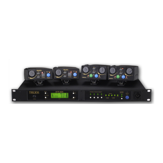
- Page 1 BTR-80N, TR-80N, TR-82N Professional Wireless Intercom System Operating Instructions Rev. 09 JUNE / 2019 F.01U.195.915...
- Page 2 BTR-80N, TR-80N, TR-82N ROPRIETARY OTICE The product information and design disclosed herein were origi- nated by and are the property of Bosch Security Systems, Inc. Bosch reserves all patent, proprietary design, manufacturing, repro- duction, use and sales rights thereto, and to any article disclosed therein, except to the extent rights are expressly granted to others.
- Page 3 BTR-80N, TR-80N, TR-82N Important Safety Instructions Read these instructions. Keep these instructions. Heed all warnings. Follow all instructions. Do not use this apparatus near water. Clean only with dry cloth. Do not block any ventilation openings. Install in accordance with the manufacturer’s instructions.
- Page 4 BTR-80N, TR-80N, TR-82N...
-
Page 5: Table Of Contents
Auxiliary Settings ..........38 System Features ............ 9 ClearScan .............38 Controls and Connections ........10 Lockout ..............39 BTR-80N – Front Panel .......... 10 Copy ..............39 BTR-80N – Rear Panel ........... 11 1st Use Defaults ............39 Specifications ............12 Factory Default .............39 TR-80N - Top Panel .......... - Page 6 RF Monitor Screen ..........70 Setting Beltpack ID ..........70 ADDITIONAL RESOURCES ......71 BTR-80N Menu Structure ........72 TR-80N Beltpack Screen Flowchart ....... 73 TR-82N Beltpack Screen Flowchart ....... 74 Frequency Bands ..........75 North America ............. 75 Europe ..............
-
Page 7: General Description
Two (2) independent channels of intercom audio with the • ability to operate party line and RTS matrix on the same the flexibility to create a party line and a private line within the intercom channel at the same time. -
Page 8: Controls And Connections
10 Introduction BTR-80N, TR-80N, TR-82N Controls and Connections BTR-80N – Front Panel BTR-80N - Front Panel FIGURE 1. Power Switch - Do not power up a base station within three microphone is automatically detected. Microphone gain and (3) seconds of the unit being turned off. Voltages within the volume are configured in the software menus. - Page 9 BTR-80N, TR-80N, TR-82N Introduction 11 BTR-80N – Rear Panel BTR-80N - Rear Panel FIGURE 3. Receive Antenna - Female “TNC” Connector. Color band on antenna must match color dot on base station. Relay Contact - A dry contact closure which activates when a beltpack user presses the stage announce (SA) button.
- Page 10 12 Introduction BTR-80N, TR-80N, TR-82N Specifications Overall RF Frequency TX Range 482 - 608 MHz in 18 MHz TX bands RX Range US/Canada 572 - 608 MHz in 18 MHz RX bands 653 - 663 MHz for 3 band Rest of the World...
-
Page 11: Introduction 13
BTR-80N, TR-80N, TR-82N Introduction 13 Stage Announce Relay Dry contact, rated at 1 Amp, 24V Max Microphone Input Sensitivity Local Headset Output 40mW output into 600Ω (1% Distortion) Transmitter Type Two Synthesized Transmitters Transmit Power (each transmitter) Selectable: off, 10mW, 50mW, 100mW, 249mW... - Page 12 14 Introduction BTR-80N, TR-80N, TR-82N TR-80N - Top Panel TR-80N Top Panel FIGURE 4. On/Off Volume Control - Turns the beltpack power on. Bat/Peak Light (BAT/PK) Light flashes once when unit turns on if the battery is good. If the light stays on, the Wireless Talk-Around (WTA) - When pressed, the user’s...
-
Page 13: Btr-80N - Rear Panel
BTR-80N, TR-80N, TR-82N Introduction 15 TR-80N Rear Panel/Connector/Antennas FIGURE 5. MENU and SET buttons- Use to select menus and set options on the LCD. LCD (Liquid Crystal Display) UP and DOWN buttons - Use to select beltpack options on the LCD. -
Page 14: Specifications
16 Introduction BTR-80N, TR-80N, TR-82N Specifications Overall RF Frequency TX Range US/Canada 572 - 608 MHz in 18 MHz TX bands 653 - 663 MHz for 3 band Rest of the World 572 - 608, 614 - 722 MHz in 18 MHz TX bands... - Page 15 BTR-80N, TR-80N, TR-82N Introduction 17 RF Frequency Stability 2.5PPM Modulation Limiter Peak-Responding Compressor Radiated Harmonics &Spurious Exceeds FCC specifications Receiver Type Triple Conversion Superheterodyne, Synthesized FM RF Sensitivity <0.6V for 12dB SINAD Squelch Threshold adjustable - 12/20/24dB SINAD (about 1.0 μV)
-
Page 16: Tr-80N - Top Panel
18 Introduction BTR-80N, TR-80N, TR-82N TR-82N – Top Panel TR-82N Top Panel FIGURE 7. On/Off and Volume Control - Turns beltpack power on Low Battery/Peak (BAT/PK) Light - Light flashes once and controls headset volume for intercom channels “1” and when unit is turned on if the battery is good. - Page 17 4-pin Telex/RTS units are monaural. 5- pin Telex/RTS units have a software setup to select if XLR pin 3 or 5 is the channel 2 output and if pin 3 is ground. Battery Latch - Press down to release the battery pack.
-
Page 18: Specifications
20 Introduction BTR-80N, TR-80N, TR-82N Specifications Overall RF Frequency TX Range US/Canada 572 - 608 MHz in 18 MHz TX bands 653 - 663 MHz for 3 band Rest of the World 572 - 608, 614 - 722 MHz in 18 MHz TX bands... -
Page 19: Specifications
BTR-80N, TR-80N, TR-82N Introduction 21 Peak-Responding Compressor Radiated Harmonics &Spurious Exceeds FCC specifications Receiver Type Two, Triple Conversion Superheterodyne Receivers, Synthesized, FM RF Sensitivity <0.6 V for 12 dB SINAD Squelch Threshold adjustable - 12/20/24 dB SINAD IF Selectivity 6 dB at 30 kHz bandwidth... - Page 20 22 Introduction BTR-80N, TR-80N, TR-82N...
-
Page 21: Installation
CHAPTER 2 Installation Unpacking Contact the shipper or your dealer immediately if anything is Unpack your RTS System. Below are the items that should damaged or missing. come with your base station and each beltpack. Quantity Description BTR-80N Base Station... -
Page 22: Antenna Connection
The antenna should be vertically aligned. Attaching Receive 1/2-Wave Antenna FIGURE 11. Antenna Polarization The RTS Wireless Intercom System is vertically polarized. This means both the transmitting and receiving antennas should operate in the vertical position. Attaching Transmit 1/2-Wave Antenna FIGURE 10. -
Page 23: Distance Between Antennas
The antennas can be remotely mounted for a better signal path. An RTS coax assembly with remote antennas may be required. See “Accessory” section for ordering information. NOTE:... - Page 24 22 Installation BTR-80N, TR-80N, TR-82N Attempting to operate the wireless intercom system through or around walls, ceilings, metal objects, etc. reduces system range and performance. Operating System Near Obstructions FIGURE 16. IMPORTANT: DO NOT mount the base station 1/2- wave antennas on or next to: metal, such as beams;...
-
Page 25: Improving Reception And Increasing Range
BTR-80N, TR-80N, TR-82N Installation 23 Antenna Placement FIGURE 17. Improving Reception and Increasing Range Keeping the distance from the base station and beltpack as short and unobstructed as possible produces the most reliable antenna performance. The base station is supplied with two (2) antennas. This provides satisfactory system performance in most applications. System range can be enhanced by remotely mounting the 1/2-wave antennas. - Page 26 24 Installation BTR-80N, TR-80N, TR-82N...
-
Page 27: Operation
The ability for users to enter frequencies of their own via 12 • Basic Operational Description user-defined groups The BTR-80N narrow band wireless intercom system offers the most comprehensive, user-friendly, and versatile set of features System Quick Start available in wireless intercom systems anywhere in the world. -
Page 28: Transmit And Receive Antennas
2-wire external audio intercom systems. These XLR jacks are designated intercom 1 and 2 on the rear panel. They accept Telex, RTS, and Clear-Com types of intercom systems. The pinouts of these standard types of intercom are shown in Figure 19. - Page 29 Since RTS-TW carries both channels of audio on one (1) cable, the four (4) intercom XLR connectors are connected in parallel when RTS is selected. Thus any one (1) of the four (4) intercom XLRs may be used for RTS input. Looping through of the audio, shown in Figure 21, may also be accomplished via any of the rear panel XLRs when in FTS mode.
-
Page 30: 4-Wire Intercom Ports
The auxiliary output jack is a 3-pin XLR jack. It produces a line level balanced output. Please refer to Figure 25. The BTR-80N can connect to two (2) 4-wire audio intercom systems. These 6-pin modular jacks (RJ-11) are designated 4- wire under intercom 1 and 2 titles on the rear panel. -
Page 31: Base Station Link
BTR-80N, TR-80N, TR-82N Operation 29 BTR-80N Rear View FIGURE 26. Base Station Link Stage Announce (SA)/Relay This pair of RJ-45 jacks allow the passage of WTA, WTA The Stage Announce 3-pin XLR connector (see Figure 26) is termination control voltage, and CAN bus data between where audio exits the base when a beltpack user presses the SA multiple base stations. -
Page 32: Base Station Link Jack
• Straight through cable. Passes CAN data, WTA – WTA 1 and WTA 2 in the BTR-80N are two (2) independent 2- audio, and WTA termination signal. wire intercom channels. Up to 16 base stations may be CAN Bus Termination Cable (CTC) •... -
Page 33: Powering The Base Station
Start Up Screen Status Screen FIGURE 36. When the BTR-80N powers up, the first screen displayed is the Start Up splash screen. It displays for about three (3) seconds. This screen contains both the software version number and band ID of the base. Figure 35 shows a screen indicating software... -
Page 34: Rssi Screen
32 Operation BTR-80N, TR-80N, TR-82N RSSI Screen User-defined groups 18u to 30u may be changed by the user to any frequency within range of the base. RSSI stands for Received Signal Strength Indicator. This screen displays the detected signal strength of each of the four (4) receivers in the base. -
Page 35: Frequency Edit (User-Defined Groups Only)
BTR-80N, TR-80N, TR-82N Operation 33 displays the group and frequencies selected, and then Base Main Settings returns to the main screen. Settings contained in the base main menu are the following: Local headset microphone gain • Frequency Edit (User-Defined Groups Only) Local headset volume •... -
Page 36: Local Headset Volume And Gain
34 Operation BTR-80N, TR-80N, TR-82N Local Headset Volume and Gain To access the transmit power settings, do the following: The Local Headset Volume and Microphone Gain are set in From the main status screen, press MENU. the following software screen. -
Page 37: Stage Announce Level
BTR-80N, TR-80N, TR-82N Operation 35 Press SET. To set the stage announce level, do the following: The receiver 1 squelch setting starts flashing. From the status screen, press MENU. Using the UP/DOWN arrow buttons, adjust the setting. Using the UP/DOWN arrow buttons, select Base Main. -
Page 38: Can Bus Number
NOTE: The base defaults back to the status screen if no There are multiple parameters to set in the Intercom Setting action is taken after five (5) minutes. menu: 2-wire intercom type: Telex, RTS, Clear-Com, Off • CAN Bus Number Only intercom 1 active, only intercom 2 active, both •... -
Page 39: 2-Wire Intercom
BTR-80N, TR-80N, TR-82N Operation 37 2-Wire Intercom 4-Wire Intercom The screens below show the progression of setting 2-wire The screens below show the progression of setting 4-wire parameters. parameters. 4-Wire Intercoms 2-Wire Intercoms FIGURE 49. FIGURE 50. To adjust the 2-wire intercom settings, do the following: To adjust the 4-wire intercom settings, do the following: From the status screen, press the MENU button. -
Page 40: Auxiliary Settings
38 Operation BTR-80N, TR-80N, TR-82N Auxiliary Settings NOTE: The base defaults back to the status screen if no action is taken after five (5) minutes. The parameters to configure in the auxiliary setting menu are as follows: ClearScan Intercom 1 Auxiliary mode: Local, Global, or Off •... -
Page 41: Lockout
BTR-80N, TR-80N, TR-82N Operation 39 Lockout 1st Use Defaults Lockout is used to keep a user from changing any options at the 1st Use Defaults is used to set the base station to Group 01A, base station, except local headset microphone gain and volume. -
Page 42: Connection Of Multiple Base Stations With The Link Cables
40 Operation BTR-80N, TR-80N, TR-82N Connection of Multiple Base Stations with the Link connected via standard 2-wire and 4-wire intercoms without additional link cables between them. They still transmit and Cables receive intercom 1 and intercom 2 audio normally from the This section discusses various configurations of multiple base beltpacks. -
Page 43: Over-The-Air Data Links
BTR-80N, TR-80N, TR-82N Operation 41 Before presenting the configurations, we believe an explanation Beltpack-to-base conveys: • of RF data links plus master and servant base stations helps in Current button(s) selected – understanding the multiple base arrangements. Battery level –... - Page 44 42 Operation BTR-80N, TR-80N, TR-82N Three (3) base stations connected via 2-wire intercom only FIGURE 58. Two (2) bases have their transmitter off; one has its transmitters on...
-
Page 45: Master And Servant Base Stations
A CAN (Controlled Area Network) bus is the data protocol used over the BTR-80N’s base station link cable. This balanced protocol is a robust standard used the world over in high noise, extreme environments. - Page 46 44 Operation BTR-80N, TR-80N, TR-82N CAN Bus 120 Ohm termination (CAN-T) and FIGURE 62. base pin functions. Part Number: PRD000223002 (not supplied) A base link cable connected system with terminators on both ends FIGURE 63.
-
Page 47: Base Station Link Configurations
• Base station link input and output jacks FIGURE 64. Bases connected via 2-wire and/or 4-wire audio – on the rear of the BTR-80N links All bases share WTA audio – All bases are ON A SINGLE CAN BUS –... -
Page 48: Wireless Talk-Around Audio Only
WTA channel 2 audio but do not share the CAN bus data. Link Overview WTA 1 and WTA 2 in the BTR-80N are two (2) independent 2- wire intercom channels. The WTA intercom channels are very similar to AudioCom types of intercom channels except they are dry and are meant to only pass audio between BTR-80N base stations. -
Page 49: Setup
If all units are on Setup via the BTR-80N software menus the intercom, local a common power strip, this is controlled headset, auxiliary, stage announce, etc. as detailed in by a built in delay on the master base BTR-80N Operation. -
Page 50: Setup
NOTE: Leave the base number at the default of 09. Connect the main intercom audio channel(s) to the base Setup via the BTR-80N software menus the intercom, local stations. headset, auxiliary, stage announce, etc. as detailed in BTR-80N Operation. -
Page 51: Wta And Several Can Bus Networks
BTR-80N, TR-80N, TR-82N Operation 49 Cycle the power of the master base while leaving the WTA and Several CAN Bus Networks single servant base powered-up. These base stations may be connected via 2-wire and/or 4-wire The master base, on boot, takes control of the servant base audio links. - Page 52 OFF automatically when the master base takes control of them. NOTE: Leave the base number at the default of 09. Setup via the BTR-80N software menus the intercoms, local headset, auxiliary, stage announce, etc., as detailed in BTR-80N Operation.
- Page 53 BTR-80N, TR-80N, TR-82N Operation 51 Multiple base stations connected via 2-wire FIGURE 69. audio cable and two CAN Bus networks.
-
Page 54: Basic Operational Description
The TR-80N/82N is a full-duplex (simultaneous talk and The following is a list to quickly get a base station and beltpacks listen) beltpack. It works in conjunction with a BTR-80N base operating. station. The beltpack allows a user, via a headset attached to Unpack the base. -
Page 55: Battery Installation
BTR-80N, TR-80N, TR-82N Operation 53 Battery Installation Ensure the On/Off volume control knob is turned off. Press down and hold down the battery release latch, then slide the battery pack about 1/8 inch back toward the latch until it stops. -
Page 56: Headset Connection
54 Operation BTR-80N, TR-80N, TR-82N FIGURE 72. TR-80N/82N Controls Headset Connection Antenna Connection The Headset Connector is a XLR type connector. Four The beltpack comes with two detachable, screw type 1/4 (4) or five (5) pin headset connectors may be installed wave antennas. -
Page 57: On/Off And Volume Control
BTR-80N, TR-80N, TR-82N Operation 55 FIGURE 73. TR-80N Top Panel Controls On/Off and Volume Control To select the TALK button mode, do the following: Press and hold SET while pressing the TALK button. To turn the beltpack power on, do the following: The current mode of the TALK button displays the first time Rotate the On/Off Volume Control knob(s) CW. -
Page 58: Stage Announce (Sa)
56 Operation BTR-80N, TR-80N, TR-82N Stage Announce (SA) To route audio from the beltpack directly to the stage announce connector on the back of the base station, do the following: Press the SA button. > The base station’s SA relay is also closed. The beltpack sidetone is lost as an indication that stage announce is activated. -
Page 59: Groups And Channels
BTR-80N, TR-80N, TR-82N Operation 57 Groups and Channels The first LCD screen the beltpack displays is the Group/ Channel screen. This screen shows the currently selected receive group followed by the beltpack transmit channels. To edit groups and channels, do the following: Push SET to edit the transmit channel. -
Page 60: Receive Frequency
58 Operation BTR-80N, TR-80N, TR-82N Receive Frequency The Receive Frequency screen displays the beltpack receiver frequencies in MHz. The frequency cannot be changed in factory-defined groups, but can be changed in user-defined groups. To edit the RX frequency (User Groups Only), do the following: Set the unit to the desired user-defined group and channels. -
Page 61: Low Battery Alert Tone
BTR-80N, TR-80N, TR-82N Operation 59 Low Battery Alert Tone Changing the Transmit Power Setting The beltpack sends an audio alert tone to the headset if battery To change the transmit power setting, do the following: life reaches 10%. The 1 kHz tone is heard for 0.5 seconds, every Push SET at the transmit power screen. -
Page 62: Squelch Screen
60 Operation BTR-80N, TR-80N, TR-82N Squelch Screen Transmit Mode Screen The Squelch screen allows the user to adjust the beltpack The Transmit Mode screen is used to select the following squelch level. modes: Transmit Description To select the beltpack squelch level, do the following: Mode Push SET at the squelch screen. -
Page 63: Software Version/Band
BTR-80N, TR-80N, TR-82N Operation 61 Software Version/Band The degree of interference found for R1 and R2 displays on the far-right two (2) positions on the screen. The software revision and frequency band of the beltpack may be displayed from any of the main beltpack screens. -
Page 64: Rf Monitor Screen
62 Operation BTR-80N, TR-80N, TR-82N RF Monitor Screen Setting Beltpack ID The RF monitor screen displays beltpack RF status. Several functions require the beltpack to know which base and channel it is associated with. To display the beltpack RF status, do the following: Auto Power Setting: The beltpack reduces its TX •... -
Page 65: On/Off And Volume Control
BTR-80N, TR-80N, TR-82N Operation 63 TR-82N Top Panel Controls FIGURE 77. On/Off and Volume Control he battery/peak lights indicate battery condition and audio modulation status. To turn the beltpack power on, do the following: Battery Light flashes on power up = Battery OK Rotate the On/Off Volume Control knob(s) CW. -
Page 66: Wireless Talk-Around (Wta)
64 Operation BTR-80N, TR-80N, TR-82N Wireless Talk-Around (WTA) To disconnect the beltpack audio from the wired intercom, auxiliary input/output, and the base station’s local headset, do the following: Press the WTA button. > Other beltpack users on that audio channel can hear the user as normal. -
Page 67: Groups And Channels
BTR-80N, TR-80N, TR-82N Operation 65 Groups and Channels The first LCD screen the beltpack displays is the Group/ Channel screen. This screen shows the currently selected receive group followed by the beltpack transmit channels. To edit groups and channels, do the following: Push SET to edit the transmit channel. -
Page 68: Receive Frequency
66 Operation BTR-80N, TR-80N, TR-82N Receive Frequency The Receive Frequency screen displays the beltpack receiver frequency in MHz. The frequency cannot be changed in factory- defined groups, but can be changed in user-defined groups. To edit the RX frequency (User Groups Only), do the following: Set the unit to the desired user-defined group and channels. -
Page 69: Low Battery Alert Tone
BTR-80N, TR-80N, TR-82N Operation 67 Low Battery Alert Tone To change the transmit power setting, do the following: The beltpack sends an audio alert tone to the headset if battery Push SET at the transmit power screen. life reaches 10%. The 1 kHz tone is heard for 0.5 seconds, every Using the UP/DOWN arrow buttons, select the power 30 seconds. -
Page 70: Squelch Screen
68 Operation BTR-80N, TR-80N, TR-82N Squelch Screen Setting Auxiliary Input Function The Squelch screen allows the user to adjust the beltpack Aux input disabled squelch level. Aux heard with Ch 1 Aux heard with Ch 2 To adjust the squelch level, do the following: Aux heard with Ch 1 &... -
Page 71: Leds Off/On
BTR-80N, TR-80N, TR-82N Operation 69 LEDs Off/On Clear groups are displayed first. They are in group order. You can scroll down through groups using the DOWN button. The The LED Off/On screen is used to disable all LEDs. This left-half of the screen gives you an indication of interference function is useful for users who do not wish to show LEDs in levels as you scroll through the groups. -
Page 72: Factory Reset
70 Operation BTR-80N, TR-80N, TR-82N Factory Reset Setting Beltpack ID Factory Reset sets the beltpack to Group 1A, channel 1 and Several functions require the beltpack to know which base and ERASES any user-defined groups in memory. It sets a unit to channel it is associated with. -
Page 73: Additional Resources
APPENDIX A Additional Resources BTR-80N Menu Structure... - Page 74 BTR-80N, TR-80N, TR-82N...
-
Page 75: Tr-80N Beltpack Screen Flowchart
BTR-80N, TR-80N, TR-82N TR-80N Beltpack Screen Flowchart... -
Page 76: Tr-82N Beltpack Screen Flowchart
BTR-80N, TR-80N, TR-82N TR-82N Beltpack Screen Flowchart... -
Page 77: Frequency Bands
BTR-80N, TR-80N, TR-82N Frequency Bands Band Names Frequencies and US TV Channels FIGURE 81. The BTR-80N system operates over the following frequency ranges: Band US TV Freq. Freq. US TV Start North America Base TX: 482-608 MHz – Base RX: 572-608 MHz, US 3 Band: 653-663 MHz –... -
Page 78: Frequency Plan
BTR-80N, TR-80N, TR-82N Frequency Plan There are 48 groups in a BTR-80N system. The 48 groups are divided up into 36 factory-defined groups and 12 user-defined groups. A group referenced to a base station is comprised of two TX channels and up to 12 RX channels. -
Page 79: Troubleshooting
BTR-80N, TR-80N, TR-82N Troubleshooting PROBLEM SOLUTION DISTORTION - System’s audio quality seems distorted at Reduce microphone gain by adjusting microphone gain medium to high input levels control in software. HISS - System seems to produce a hiss which is Check the gain setting on all beltpacks and the base. They undesirable. -
Page 80: Battery Information
BTR-80N, TR-80N, TR-82N Battery Life Battery Information TR-80N Improper battery selection, use, installation, and care are the Alkaline, 11-13 hours typical cause of numerous wireless systems failures. Nickel-Metal Hybrid, 10-12 hours typical Alkaline Batteries: Alkaline batteries such as Eveready’s TR-82N... -
Page 81: 2-Wire Systems Specification
BTR-80N, TR-80N, TR-82N 2-Wire Systems Specification... -
Page 82: Certificate Information
Antenna minimum safe distance, for a base station, as set selected. RTS strongly urges the user to contact the appropriate by the FCC is 20cm. Antenna gain: zero (0) dBd referenced telecommunications authority for any clarification. - Page 83 Pour se conformer aux exigences FCC et Industrie Canada l'exposition aux RF sur une distance de séparation d'au moins 20 cm (7,9 pouces) doit être maintenue entre les antennes de la station de base BTR-80N et toutes les personnes.
- Page 84 LI, LT, LU, MT, PL, PT, SK, SE, CH, UK. The BTR-80N, TR-80N and TR-82N must be set to meet the 50 mW ERP maximum output power in the following countries: AT, BE, CY, CZ, DK, EE, FL, FR, DE, EL, HU, IS, IT, LV, LI, LT, LU, MT, NL, NO, PL, RO, SK, SI, ES, SE, UK.
-
Page 85: Accessories And Replacement Parts
BTR-80N, TR-80N, TR-82N Accessories and Replacement Parts ALP-700 450-760 MHz Bi-directional Log Periodic Antenna Model (CTN) No. ALP-700 ALP-450 450-900 MHz Log Periodic Antenna Includes mounting hardware and 10 feet (3 meters) coaxial cable with TNC connectors Model (CTN) No. ALP-450 ALP-600 520-760 MHz Bi-directional Log Periodic Antenna ... - Page 86 BTR Power Cords CTC, BTR-80N CAN BUS Model (CTN) No. Termination Cable North America Model (CTN) No. PC-USA Model (CTN) No. CTC, BTR-80N CAN BUS CAN-T U.K. Model (CTN) No. 120 Termination PC-UK BP-700 TR Battery pack, Model (CTN) No.
- Page 87 BTR-80N, TR-80N, TR-82N Base Station: Flexible Ground Independent Dipole Antenna Frequency Band Designators Frequency Model Band Coverage of (CTN) No. Color Antenna Red/ 470 - 550 FA-RW-RS White Yellow/ 525 - 610 FA-YW-RS White Green/ 610 - 710 FA-GW-RS White...
-
Page 88: Three (3) Band Base Stations
BTR-80N, TR-80N, TR-82N Changing Channel Maps Three (3) Band Base Stations A three band base station may be changed from a normal channel map to a US channel map and back again with the press Identifying a Three (3) Band Unit of a couple of buttons. - Page 89 BTR-80N, TR-80N, TR-82N...
- Page 90 Bosch Security Systems, Inc. 12000 Portland Avenue South Burnsville, MN 55337 U.S.A. www.boschcommunications.com...
Need help?
Do you have a question about the BTR-80N and is the answer not in the manual?
Questions and answers