Table of Contents
Advertisement
User manual
Control Unit for an Electric
Height-Adjustable Desk
COMPACT
For firmware version 1.7.6 or higher
Rev 3
Subject to change without notice. Errors and omissions excepted.
LOGICDATA cannot accept responsibility for incorrect operation or use of
the products other than for the intended purpose.
Under the warranty terms, LOGICDATA shall replace or repair any products
that prove defective at the time of delivery. LOGICDATA shall not assume
any further liability.
If you have any questions or special requests, please contact LOGICDATA
direct.
©2011 LOGICDATA
Advertisement
Table of Contents

Related Manuals for LOGICDATA COMPACT


Summary of Contents for LOGICDATA COMPACT
- Page 1 Under the warranty terms, LOGICDATA shall replace or repair any products that prove defective at the time of delivery. LOGICDATA shall not assume any further liability. If you have any questions or special requests, please contact LOGICDATA direct.
-
Page 2: Table Of Contents
3.2.3 Connect optional components............. 14 3.2.4 Connect mains supply................. 15 3.2.5 System configuration (example)............15 Operating the COMPACT control unit ............... 16 Basic functions ................... 16 4.1.1 Upward desktop movement..............16 4.1.2 Downward desktop movement ............17 Advanced functions ..................17 4.2.1... - Page 3 Technical data ....................30 Appendix ......................32 Possible faults and remedies ..............32 Error messages on the handswitch display ..........33 Error indication with LEDs ................35 Click codes....................37 Optional products ..................38 6.5.1 Handswitches..................38 Drill template ....................40 Further information ....................
-
Page 4: Preface
1.1 Intended use COMPACT control units may only be used for the intended purpose, i.e. to control electric height-adjustable desks. Only motors that meet LOGICDATA specifications may be used to drive the lifting devices. The control units must be installed, put into operation and their function checked by qualified personnel. -
Page 5: Target Group And Previous Knowledge
Failure to observe this warning may cause injuries and damage to property. Note: this symbol advises you of important information that must be noted for operating the COMPACT control unit safely. Danger: this warning advises you of a possible risk of body parts being trapped or pinched in exceptional cases. -
Page 6: Isp (Intelligent System Protection)
1.5 ISP (Intelligent System Protection) ISP is an electronic state-of-the-art protection system developed by LOGICDATA. It also substantially reduces the risk of fingers being trapped or pinched. Danger: in spite of ISP being in place, there may still be a risk of... -
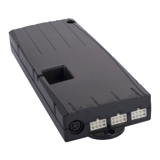
Page 7: Package Contents
1.6 Package contents The COMPACT control unit is supplied together with the following components as standard: Figure 1: Package contents COMPACT control unit Note: power cords can be ordered separately. For detailed information on optional control unit components and accessories, see page 38. -
Page 8: General Safety Instructions
Caution: only use the power cord supplied with the control unit. Check that it is not damaged. Do not ever operate the COMPACT control unit if the power cord is damaged. Danger: it is not allowed to connect self constructed products to LOGICDATA motor controls. - Page 9 Note: only clean the COMPACT control unit with a dry or slightly moist cloth. Before cleaning, you must always unplug the power cord. Note: in case of a mains power breakdown or if the power cord is...
-
Page 10: Important Notes For Oems
1.8.2 Important notes for OEMs What we mean by OEMs are companies that purchase COMPACT control units from LOGICDATA and install them in their own products (e.g. electric height-adjustable desks). Note: for reasons of EU conformity and product safety, we advise you to provide users of your products with a manual in the relevant EU language. -
Page 11: Compact Installation Instructions
2. COMPACT installation instructions Mount the COMPACT control unit on the underside of the desktop. You will need the following tools for mounting: • Cross-tip screwdriver • Pencil • Drill (for drilling holes) Caution: the power cord must be unplugged while the COMPACT control unit is being mounted. -
Page 12: Tco 04 Conform Mounting
To guarantee the TCO 04 conformity of the system, the control unit has to be mounted at the position shown in the picture below. Figure 3: TCO 04 conform mounting position of the COMPACT, Top-view of the table Page 12 / 43... -
Page 13: Commissioning
COMPACT control unit. Requirements for commissioning: • The COMPACT control unit must be mounted (as described in section 2) • The table legs for adjusting the desktop must be mounted Danger: only qualified technicians may commission the control unit. -
Page 14: Commissioning Procedure
This clamp is also marked with the symbol on top of the housing. 3.2 Commissioning procedure Caution: the power cord must be unplugged while the COMPACT control unit is being commissioned. To commission a COMPACT control unit, proceed as follows. -
Page 15: Connect Mains Supply
• All the components must be plugged into the right sockets • The earthing cable must be connected When the power cord is plugged in, the COMPACT control unit is operational. Note: in case of a mains power breakdown or if the power cord is... -
Page 16: Operating The Compact Control Unit
4. Operating the COMPACT control unit To ensure safe operation of the COMPACT control unit, please observe the following safety instructions: Note: in case of a mains power breakdown or if the power cord is plugged off during the movement of the drives, a manual reset of the... -
Page 17: Downward Desktop Movement
This function allows you to save a defined desktop height .One desktop height can be saved per memory position key. To save a position, proceed as follows: Note: if you are switching on the COMPACT control unit for the first time, all the saved positions are set to the lowest desktop height (minimum desktop position). -
Page 19: Changing The Desktop Height Displayed
4.2.3 Changing the desktop height displayed This function enables you to change the height shown on the display, but not the actual position of the desktop. Proceed as follows: Press the memory key. The display will read S –. Press the desktop down key (down arrow) for approx. 5 seconds. -
Page 20: Manual Reset
4.2.4 Manual reset When the actual desktop position no longer corresponds to the height displayed or you wish to use a configured control unit on another identical electric height- adjustable desk, you have to reset the lowest desktop position to the minimum height. -
Page 21: Enabling Limit Position Calibration
4.2.5 Enabling limit position calibration The service technician enables limit position calibration during the commissioning procedure. Note: availability of the S 7 function depends on the parameters set for the control unit. A handswitch with display and memory keys is necessary. -
Page 22: Limit Position Calibration
4.2.6 Limit position calibration The limit positions must be calibrated during commissioning after the control unit has been installed. Note: there is the option of having all the settings required for commissioning carried out at the factory. Note: a handswitch with display and memory keys is necessary. To calibrate the limit positions, proceed as follows: 068 flashes on the display. -
Page 23: Software-Dependent Functions
Please note that there is a potential risk of pinching in this case. 4.3 Software-dependent functions Note: prior to shipping, the COMPACT control unit is parameterized with the software. The following functions are only available if the control unit has been configured accordingly. -
Page 24: Container- And Shelf-Stop Positions
A container stop position can only be stored in the lower half of the movement area and a shelf stop in the upper half. Press S for 10 seconds. The COMPACT will click twice when the container stop position is stored. -
Page 25: Plug Detection
In addition, the control unit detects whether a motor has been replaced (this function depends on the motor used). If a motor is missing or if it is replaced, the COMPACT will click three times. Additionally the corresponding error code will be displayed if the handswitch is equipped with a display (For the error code list, see page 33). -
Page 26: Drive Back
Please follow the safety instructions in the manual and treat our product with due care. 4.3.6 Anti-Pinch configuration If the pinch protection device ACS-CB-SENS is attached to the COMPACT, the risk of pinches is decreased. To activate the ACS-CB-SENS, go on as shown below: Possible situations: •... -
Page 27: Duty Cycle Monitoring
As the control unit manufacturer, LOGICDATA does not have an effect on this residual risk and cannot therefore accept any liability. Please follow the safety instructions in the manual and treat our product with due care. -
Page 28: Change Number Of Drives
4.3.8 Change number of drives It is possible to adjust the number of drives which can be controlled by a COMPACT. A COMPACT-3 can control one, two or three, a COMPACT-2 one or two motors according to the chosen settings. - Page 29 Press the memory key to confirm the setting. If 000 flashes on the display, a reset is necessary. This procedure is explained in section 4.2.4. If 068 flashes on the display, a calibration is necessary. This procedure is explained in section 4.2.6. Note: 068 is shown if the handswitch display is set up to show the height in centimetres.
-
Page 30: Technical Data
5VDC ±10% 250mA electronics and Hall sensors Precision of Motor current measurement @ 100% Output Voltage and 4-8A per Motor ±20% Other cases Contact LOGICDATA Ambient temperature 0-30° C Relative humidity (for operation) 5-85% (non condensing) Storage and transport temperature -40-85°... - Page 31 Weight (typical) 490g Nameplate The figure below shows the nameplate and its location on the control unit. Note: the details on the nameplate depend on the COMPACT control unit model (see technical data). Figure 6: Nameplate Page 31 / 43...
-
Page 32: Appendix
6. Appendix In this section you will find detailed information on the following topics: • Possible faults and remedies • Error messages on the handswitch display • Error indication with LEDs • Click codes • Optional products • Drill template 6.1 Possible faults and remedies Drives not working Possible cause... -
Page 33: Error Messages On The Handswitch Display
Overcurrent motor group 2 Collision protection Overcurrent control unit Note: the COMPACT can be parameterized so that a manual reset (see page 20) must be carried out after an overcurrent error (E24, E25, E26, E48, E49 and E62). Page 33 / 43... - Page 34 In some exceptional cases this storage is not possible and the error E81 is shown on the handswitch display (if available) and the COMPACT clicks three times. To rectify this error, a manual reset is necessary (see page 20).
-
Page 35: Error Indication With Leds
6.3 Error indication with LEDs Depending on the version, the COMPACT is equipped with LEDs to indicate errors even if a handswitch without display is used. These LEDs are placed on the housing top over the handswitch socket and each motor socket. - Page 36 Error Code: Control box LED is on Description: Remedy: Reset necessary Make a manual reset. Note: The LED is still on while the reset movement or if reset is not completed. It is deactivated when the reset is finished. Error Code: A Motor channel LED is blinking Description: Remedy:...
-
Page 37: Click Codes
Reset all motors. 6.4 Click codes When the control unit is switched on the COMPACT uses its relays to inform the user acoustically about the system state and the reason why the control unit was switched off before. The table below shows which number of clicks corresponds to certain information. -
Page 38: Optional Products
6.5 Optional products The following optional products are available for COMPACT control units. Note: you can only use some of the COMPACT control unit functions if the optional product is installed. 6.5.1 Handswitches LOGICDATA supplies various handswitch models with different features. The following handswitches are compatible with the COMPACT control unit family. - Page 39 • 5 memory keys • 2 movement keys • Display • Silver • Soft touch keys HSM-OD-2-LD • Competitive price • Compact size • Ergonomic design HSF-MDF-4M4-LD • Flat design • Display with status indicated • Soft touch keys • Mechanism...
-
Page 40: Drill Template
6.6 Drill template Cut out the drill template and mark the drill holes on the desktop. Note: place this drill template with the depicted side up on the position where the COMPACT shall be mounted! Page 40 / 43... -
Page 42: Further Information
7. Further information 7.1 End of life disposal When you no longer require the COMPACT control unit, please note the following for disposal: Note: the COMPACT motor control box is electrical or electronic equipment according to directive 2002/96/EC and is therefore marked with the symbol depicted on the left. -
Page 43: Manufacturer
Note: this product is RoHS compliant according to directive 2002/95/EC! Note: this product is REACH compliant according to directive 2006/121/EC (Edict 1907/2006) 7.3 Manufacturer LOGICDATA Tel: +43 (0)3462 5198 0 Electronic & Software Entwicklungs GmbH Fax: +43 (0)3462 5198 530...
Need help?
Do you have a question about the COMPACT and is the answer not in the manual?
Questions and answers