Table of Contents
Advertisement
Quick Links
Advertisement
Table of Contents

Subscribe to Our Youtube Channel
Related Manuals for LOGICDATA DMD500


Summary of Contents for LOGICDATA DMD500
- Page 1 DOCUMENT VERSION 2 | OCTOBER 2019 DYNAMIC MOTION system DMD500 Manual...
- Page 2 DMD500 - OPERATING MANUAL // PAGE 2 DMD500 - Operating Manual Document Version 2.0 / October 2019 This document was originally published in English. LOGICDATA Electronic & Software Entwicklungs GmbH Wirtschaftspark 18 8530 Deutschlandsberg Austria Phone: +43 (0) 3462 51 98 0...
-
Page 3: Table Of Contents
DMD500 - OPERATING MANUAL // PAGE 3 CONTENTS General information Other applicable documents Copyright Royalty-free use of images and text Trademarks Safety Target audience General safety regulations and obligations Intended use Reasonably foreseeable misuse Explanation of symbols and signal words... - Page 4 DMD500 - OPERATING MANUAL // PAGE 4 7.3.2 Process 7.3.3 Completing Assembly Additional Information Operation Software dependent functions 8.2.1 Replacing the DMD500 Disassembly Maintenance Troubleshooting Disposal...
-
Page 5: General Information
Height-Adjustable Table Systems. The license does not include logos, designs, and page layout elements belonging to LOGICDATA. The Reseller may make any necessary changes to the text and images to adapt them for the purpose of end user documentation. Texts and images may not be sold in their current state, and may not be published or sublicensed digitally. -
Page 6: Safety
2.3 INTENDED USE The DMD500 is a Spindle Actuator for electrically Height-Adjustable Tables. It is installed by Resellers in a Height-Adjustable Column for electrically Height-Adjustable Tables. It is controlled by an integrated Control Unit. -
Page 7: Explanation Of Symbols And Signal Words
2.5 LIABILITY LOGICDATA products comply with all currently applicable health and safety regulations. However, risk can result from incorrect operation or misuse. LOGICDATA is not liable for damage or injury caused by: • Improper product use • Disregard of the documentation •... -
Page 8: Residual Risks
Residual risks associated with assembly and instal- lation of the DMD500 are listed here and throughout this Operating Manual. The risks associated with the system as a whole are listed in the System Manual. See also Chapter 1.1 Other Applicable Documents on page 5. -
Page 9: Skilled Persons
Ensure that persons with limited ability to react to danger do not take part in the assembly process The DMD500 may only be assembled by Skilled Persons. A Skilled Person is defined as someone who: • Is authorized for installation planning, installation, commissioning, or servicing of the product •... -
Page 10: Scope Of Delivery
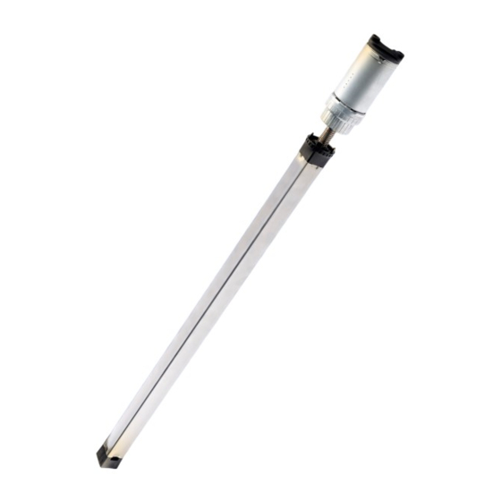
3 SCOPE OF DELIVERY Fig. 1: Scope of Delivery The standard scope of delivery for the DMD500 consists of the following components: DMD500 Linear Actuator The Top Plate Mounting Screws must be ordered from LOGICDATA separately. All other components required for assembly, e.g. the Top Plate, Bottom Plate, and the Bottom Plate Mounting Screws are to be provided by the Reseller unless otherwise stated by LOGICDATA. -
Page 11: Product
Spindle System Mounting Point Support Tube ACTUATOR DIMENSIONS Fig. 2 shows the dimensions of the DMD500 in its reset position, installation position, and extended posi- tion. Installation Length (as-develivered condition): 605.6 mm (+2 mm / - 1.5 mm) Retracted Length (reset position): 603.6 mm (+2 mm / - 1.5 mm) Extended Length (full stroke): 1102.6 mm (+2 mm / - 2 mm) -
Page 12: Pre-Assembly
Non-standard Spindle settings may only be applied with approval from LOGICDATA. NOTICE Do not lift the DMD500 by its cable. This will cause irreperable damage to the product. INFO Perform a product risk assessment so that you can respond to potential residual haz-... -
Page 13: Assembly Variants
DMD500 - OPERATING MANUAL // PAGE 13 6.2 ASSEMBLY VARIANTS There are two assembly variants for the DMD500. The variant you require depends on the type of Height- Adjustable Column that the Actuator will be installed in. These are defined as follows: •... -
Page 14: Assembly
Interface, Power Hub, etc.) for that product’s mounting instructions, and the System Manual for instruc- tions on connecting the system. The process shown in this chapter assumes the DMD500 is to be installed in a Height-Adjustable Column in which the top plate can be removed (i.e. it is not permanently connected to the Tube closest to the Table Top). -
Page 15: Step 2 - Attaching The Motor End
To attach the Motor End of the DMD500: 1. Insert the Mounting Screws through the Top Plate into the holes at the top of the DMD500 2. Use the Torque Screwdriver to tighten the Screws to 2.5 - 3 Nm. -
Page 16: Step 3 - Attaching The Spindle End
2. Use a Torque Screwdriver to tighten the Screws 7.3.3 COMPLETING ASSEMBLY After the DMD500 is attached to the Height-Adjustable Column, you must connect the Actuator Cable to the System. Refer to the DYNAMIC MOTION System Manual for instructions on your chosen configuration. - Page 17 A full list of Software-Dependent Functions can be found in the DYNAMIC MOTION System Manual. 8.3 DISASSEMBLY To disassemble the DMD500, ensure that it has been disconnected from the Power Unit. Then, follow the assembly instructions in reverse order. 8.4 MAINTENANCE The DMD500 is maintenance free for its entire service lifetime.
- Page 18 LOGICDATA LOGICDATA North America, Inc. Electronic & Software Entwicklungs GmbH 1525 Gezon Parkway SW, Suite C Wirtschaftspark 18 Grand Rapids, MI 49509 8530 Deutschlandsberg Austria Phone: +43 (0)3462 5198 0 Phone: +1 (616) 328 8841 Fax: +43 (0)3462 5198 1030 Email: office.na@logicdata.net...
Need help?
Do you have a question about the DMD500 and is the answer not in the manual?
Questions and answers