Table of Contents
Advertisement
Quick Links
NET-AIO11
Windows, Windows2000, Windows NT, Windows XP, Windows 7 and Windows CE are trademarks of Microsoft. We
acknowledge that the trademarks or service names of all other organizations mentioned in this document as their own property.
Information furnished by DAQ system is believed to be accurate and reliable. However, no responsibility is assumed by DAQ
system for its use, nor for any infringements of patents or other rights of third parties which may result from its use. No license is
granted by implication or otherwise under any patent or copyrights of DAQ system.
The information in this document is subject to change without notice and no part of this document may be copied or
reproduced without the prior written consent.
User's Manual
Copyrights 2011-2012 DAQ System Co., LTD. All rights reserved.
NET-AIO11 User's Manual (Rev 1.0)
1-
-
http://www.daqsystem.com
Advertisement
Table of Contents

Related Manuals for DAQ system NET-AIO11


Summary of Contents for DAQ system NET-AIO11
- Page 1 Information furnished by DAQ system is believed to be accurate and reliable. However, no responsibility is assumed by DAQ system for its use, nor for any infringements of patents or other rights of third parties which may result from its use. No license is granted by implication or otherwise under any patent or copyrights of DAQ system.
- Page 2 NET-AIO11 User’s Manual (Rev 1.0) Contents Introduction Product Features Hardware Device Software References (Caution) ★ The board and external input/output signals of the device have to connect the common ground(Frame) to protect the board and peripheral devices. ★ The board operates in a safe location, in a clean environment.
-
Page 3: Internal Block Diagram
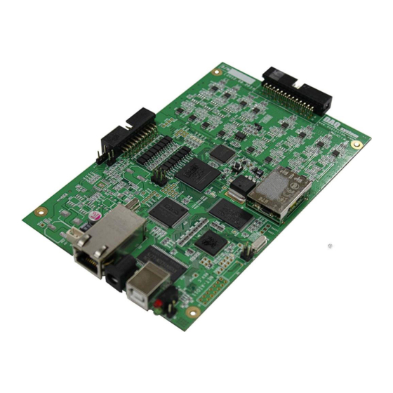
NET-AIO11 User’s Manual (Rev 1.0) 1. Introduction NET-AIO11 is the High function Signal Processing board to support Analog Input and Digital Output. The 8-channel A / D converted data by applying TI TMS320C55xx DSP chip analog signal can be obtained the high speed data via USB 2.0 interface and Ethernet interface. -
Page 4: Product Features
NET-AIO11 User’s Manual (Rev 1.0) 2. Product Features [Table 1. NET-AIO11 Specification] List Specification Interface USB B-type Connector RJ-45 Ethernet Connector Header Pin Connector for Analog Input Header Pin Connector for Digital Input/Output 5VDC Power Connector Analog Input(ADC) Channel : 8 Maximum Input Range : ±10V... - Page 5 NET-AIO11 User’s Manual (Rev 1.0) 3. Hardware Device In this chapter, board jumper set and connector for interfaced the PC or other operation equipment is described. Connector Ethernet Connector POWER Connector USB-B Connector (PWR,RUN) DSP Mode Reset Switch Setup Jumper [Figure 2.
- Page 6 NET-AIO11 User’s Manual (Rev 1.0) 3.4 AIN(Analog Signal Input) Connector (J7) Analog input signals are received an input the range of ± 10V differential (Differential) signal and a single (Single-ended) signals. In a single signal, an AINxN pin connects to the Ground of input signal, an AINxP pin connects to the input signal.
- Page 7 NET-AIO11 User’s Manual (Rev 1.0) 3.5 Ethernet Connector (J11) It connects to the Ethernet Hub or Ethernet Adapter. It automatically is detected Cross/Direct cable. 3.6 POWER Connector (J6) It is a power of the board, input over +5VDC, 1A. DC-JACK, 2mm [Table 3.
- Page 8 NET-AIO11 User’s Manual (Rev 1.0) BOX HEADER RA 2x10, 2.54mm [Table4. Digital Signal Output Connector Description] Pin No. Pin Name Description Remark DIN_COM Digital Input Common Terminal, DOUT_COM Digital Output DIN0 Digital Input 0 DOUT0 Digital Output 0 DIN1 Digital Input 1...
- Page 9 NET-AIO11 User’s Manual (Rev 1.0) 4. Software NET-AIO11 board can easily access many of the features of the library (API) to implement, and the sample program is provided to the user. 4.1 Sample Program The library is used to implement the sample program, it is organized as follows.
- Page 10 NET-AIO11 User’s Manual (Rev 1.0) board. Read from Lib It displays that the number of data bytes of read from the library buffer in application. Buffering WR Pointer It displays a saving pointer of library buffer. Buffering RD Pointer It displays a reading pointer of library buffer.
-
Page 11: Flash Load
NET-AIO11 User’s Manual (Rev 1.0) FLASH LOAD Searched File image is loaded into the board memory. Run 2~3 times more. FLASH PROGRAM Saved an image saves into the flash memory. http://www.daqsystem.com... - Page 12 NET-AIO11 User’s Manual (Rev 1.0) References 1. USB 2.0 System Architecture -- Don Anderson, USB SIG(www.usb.org) 2. Universal Serial Bus Specification -- Compaq/Intel/Microsoft/NEC, MindShare Inc. (Addison Wesley) 3. AN201 How to build application using API -- DAQ system 4. AN342 NET-AIO11 API Programming --DAQ system http://www.daqsystem.com...
Need help?
Do you have a question about the NET-AIO11 and is the answer not in the manual?
Questions and answers