Table of Contents
Advertisement
Quick Links
UVC-FRM02
User Manual
Version 1.0
ⓒ 2005 DAQ SYSTEM Co., Ltd. All rights reserved.
Microsoft® is a registered trademark; Windows®, Windows NT®, Windows XP®, Windows 7®, Windows 8®, Windows 10®
All other trademarks or intellectual property mentioned herein belongs to their respective owners.
Information furnished by DAQ SYSTEM is believed to be accurate and reliable, However, no responsibility is assumed by DAQ SYSTEM for its use, nor
for any infringements of patents or other rights of third parties which may result from its use. No license is granted by implication or otherwise under
any patent or copyrights of DAQ SYSTEM.
The information in this document is subject to change without notice and no part of this document may be copied or reproduced without the prior
written consent.
Advertisement
Table of Contents

Related Manuals for DAQ system UVC-FRM02


Summary of Contents for DAQ system UVC-FRM02
- Page 1 All other trademarks or intellectual property mentioned herein belongs to their respective owners. Information furnished by DAQ SYSTEM is believed to be accurate and reliable, However, no responsibility is assumed by DAQ SYSTEM for its use, nor for any infringements of patents or other rights of third parties which may result from its use. No license is granted by implication or otherwise under any patent or copyrights of DAQ SYSTEM.
-
Page 2: Table Of Contents
UVC-FRM02 User’s Manual Contents 1. Introduction 1-1 Product Specification ------------------------------------------------------------------------ 1-2 Product Application ------------------------------------------------------------------------ 2. UVC-FRM02 Board Function 2-1 Block Diagram ------------------------------------------------------------------------ 3. UVC-FRM02 Board Description 3-1 Board Layout ----------------------------------------------------------------------- 3-2 Device Features ------------------------------------------------------------------------ 6 3-3 Connector Pin out 3-3-1 CN1 Connector... -
Page 3: Introduction
UVC-FRM02 User’s Manual 1. Introduction UVC-FRM02 board receives a digital or analog signal selected from external HD-SDI (High-Definition Serial Digital Interface), NTSC (National Television System(s) Committee), and PAL (Phase Alternation Line) signals and converts the video data to UVC (USB Video Class) function to process and transmit. -
Page 4: Product Application
UVC-FRM02 User’s Manual 1-2 Product Application Frame Grabber Web CAM Digital Camcorder Analog Video Converter ... -
Page 5: Uvc-Frm02 Board Function
2. UVC-FRM02 Board Function 2-1 Block Diagram As shown in [Figure 2-1], in the case of UVC-FRM02, FPGA Core Logic is in charge of overall control. Its main function is to receive video signals such as HD-SDI (high-definition serial digital interface), NTSC (National Television System(s) Committee), and PAL (Phase Alternation Line) through the External I/O connector and receive UVC (USB Video) video signals. -
Page 6: Uvc-Frm02 Board Description
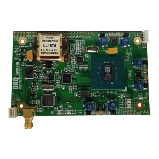
UVC-FRM02 User’s Manual 3. UVC-FRM02 Board Description Each important board function is briefly described. For detailed function information, please refer to the parts specification. 3-1 Board Layout UVC-FRM02 Board Vodeo Transfomer UVC-FRM02 Rev. C [Figure 3-1. UVC-FRM02 Layout] There are several LEDs on the board, and the description of each is as follows. -
Page 7: Device Features
UVC-FRM02 User’s Manual 3-2 Device Features Each board function will be briefly described. For detailed function information, please refer to the parts specification.. (1) FPGA : U14 All functions of the board are controlled through this FPGA Logic. (2) UVC : U6 USB Video Class is provided. -
Page 8: Connector Pin Out
UVC-FRM02 User’s Manual 3-3 Connector Pin-out The connectors and jumpers used in UVC-FRM02 will be explained. The main connectors are CN1 for USB 3.0 connection and CN2 connector for DVI connector for DVI connection. 3-3-1 CN1 Connector It is an external HD-SDI, PAL, NTSC signal line connector. - Page 9 UVC-FRM02 User’s Manual [Table 1. J6 Connector] Name Description Remark Not Connect Not Connect Not Connect Not Connect +5V Power +5V Power +5V Power +5V Power Not Connect Ground Not Connect Not Connect Ground Not Connect Not Connect Ground Not Connect...
- Page 10 UVC-FRM02 User’s Manual Ground C_SCL I2C Serial Clock 5V level Not Connect C_MODE_SEL Serial Signal Selection Signal 5V level Not Connect Ground Ground VIDEO_IN_CON HD_SDI or PAL, NTSC Serial Data 5V level USB2.0 Minus Signal Ground USB2.0 Plus Signal Ground Ground [표...
- Page 11 UVC-FRM02 User’s Manual 0x0d 0x86 0x15 0x00(default) 0x80(default) 0x14(default) 0xf3 0x7a 0x13 0xed 0x74 0x12 0xe7 0x6e 0x11 0xe1 0x68 0x10 0xd8 0x62 0x0f 0xd5 0x5c 0x0e 0xcf 0x56 0x0d 0xc9 0x50 0x0c 0xc3 0x4a 0x0b 0xbd 0x44 0x0a 0xb7...
-
Page 12: Installation
UVC-FRM02 User’s Manual 4. Installation 4-1 Product Contents Check that the contents are not abnormal. 1. UVC-FRM02 Board 2. CD ((Manual/Sample Source etc.)) 4-2 Installation Process UVC (USB Video Class) is automatically recognized by O.S without the need to install a separate driver. -
Page 13: Sample Program
UVC-FRM02 User’s Manual 5. Sample Program A sample program is provided on the CDROM provided with the board so that the board can be used easily. The executable file is FrameTest.exe. [Figure 5-1. Sample Program] (1) “Device” Selection CAM 1 ~ 3 can be selected. Cam 1 is set by default. - Page 14 UVC-FRM02 User’s Manual If you want to change the image image, you can select and apply Filter, brightness, and contrast. To switch to full screen mode, press "f" on the image screen. To close the image screen, enter "Esc" in the image screen.
-
Page 15: Appendix
UVC-FRM02 User’s Manual Appendix Board Size The external sizes of the board are as follows. (110 x 68mm) -
Page 16: Repair Regulations
⑥ Products whose serial number has been changed or removed intentionally ⑦ If DAQ SYSTEM determines that it is the customer's fault for other reasons (5) Shipping costs for returning the repaired product to DAQ SYSTEM are the responsibility of the customer. -
Page 17: References
UVC-FRM02 User’s Manual References 1. USB 3.0 System Architecture -- Don Anderson, USB SIG (www.usb.org) 2. Universal Serial Bus Specification -- Compaq/Intel/Microsoft/NEC, MindShare Inc. (Addison Wesley) 3. UVC-FRM02 Manual -- DAQ system... - Page 18 UVC-FRM02 User’s Manual MEMO Contact Point Web sit : https://www.daqsystem.com Email : postmaster@daqsystem.com...
Need help?
Do you have a question about the UVC-FRM02 and is the answer not in the manual?
Questions and answers