Table of Contents
Advertisement
Quick Links
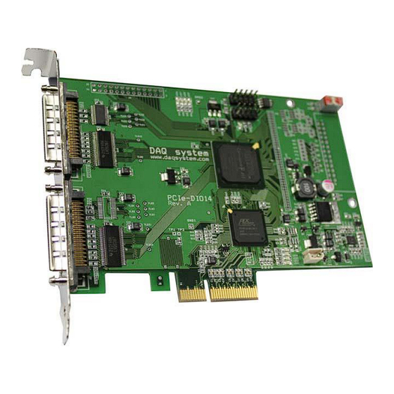
PCIe-DIO14
User Manual
Version 1.0a
ⓒ 2005 DAQ SYSTEM Co., Ltd. All rights reserved.
Microsoft® is a registered trademark; Windows®, Windows NT®, Windows XP®, Windows 7®, Windows 8®, Windows 10®
All other trademarks or intellectual property mentioned herein belongs to their respective owners.
Information furnished by DAQ SYSTEM is believed to be accurate and reliable, However, no responsibility is assumed by DAQ SYSTEM for its use, nor
for any infringements of patents or other rights of third parties which may result from its use. No license is granted by implication or otherwise under
any patent or copyrights of DAQ SYSTEM.
The information in this document is subject to change without notice and no part of this document may be copied or reproduced without the prior
written consent.
Advertisement
Table of Contents

Subscribe to Our Youtube Channel
Related Manuals for DAQ system PCIe-DIO14


Summary of Contents for DAQ system PCIe-DIO14
- Page 1 All other trademarks or intellectual property mentioned herein belongs to their respective owners. Information furnished by DAQ SYSTEM is believed to be accurate and reliable, However, no responsibility is assumed by DAQ SYSTEM for its use, nor for any infringements of patents or other rights of third parties which may result from its use. No license is granted by implication or otherwise under any patent or copyrights of DAQ SYSTEM.
-
Page 2: Table Of Contents
PCIe-DIO14 User’s Manual Contents 1. Introduction 1-1 Product Features --------------------------------------------------------------------- 2. PCIe-DIO14 Function 2-1 Board Block Diagram ------------------------------------------------------------------- LVDS and PCIe-DIO14 --------------------------------------------------------------- 3. PCIe-DIO14 Board Description 3-1 Board Layout ------------------------------------------------------------------------ Device Features ---------------------------------------------------------------------- 4. Installation Product Contents ----------------------------------------------------------------------- Driver Installation ----------------------------------------------------------------------- 5. -
Page 3: Introduction
PCIe-DIO14 User’s Manual 1. Introduction PCIe-DIO14 is a high-speed data transfer board. Connected to the host bus based on PCI Express x4, high-speed data transmission is made from the host according to the PCI-X 64-bit Split Transaction standard. Data and control signals for FIFO memory access conform to the LVDS signal standard. -
Page 4: Pcie-Dio14 Function
2. PCIe-DIO14 Function 2-1 Board Block Diagram [Figure 2-1] shows the internal function configuration of PCIe-DIO14. The board local interface is accessed by the PCI-X bus specification via "PCI Express - PCI-X Bridge". Split transmission engine, data buffering, data output and output signal control are performed in FPGA and are controlled by API commands from PC. -
Page 5: Lvds And Pcie-Dio14
PCIe-DIO14 User’s Manual 2-2 LVDS and PCIe-DIO14 The external signal input/output connector of PCIe-DIO14 uses VHDCI-68. The FIFO control signals Clock, Write Enable and Pause signals and 16-bit data signals are allocated to the J3 connector to enable 16-bit transmission. The high-order 16-bit data signal is assigned to the J2 connector, allowing 32-bit transmission when the cable is connected with the J3 connector. - Page 6 PCIe-DIO14 User’s Manual [Table 1. VHDCI-68 Connector(J2)] Pin No. Name Description Remark Pin No. Name Description Remark Reserved Reserved Unused Reserved Reserved Unused LVD+_0 DATA 0, (+), TX DATA0 LVD-_0 DATA 0, (-), TX DATA0 LVD+_1 DATA 1, (+), TX...
- Page 7 PCIe-DIO14 User’s Manual [Table 2. VHDCI-68 Connector(J3)] Pin No. Name Description Remark Pin No. Name Description Remark Reserved Reserved Unused Reserved Reserved Unused LVD+_16 DATA 16, (+), TX DATA16 LVD-_16 DATA 16, (-), TX DATA16 LVD+_17 DATA 17, (+), TX...
-
Page 8: Pcie-Dio14 Board Description
PCIe-DIO14 User’s Manual 3. PCIe-DIO14 Board Description In this chapter, the primary functions of the PCIe-DIO13 board are described briefly. For more information, refer to the device specification 3-1 Board Layout LVDS Transciver FPGA Regulators PCI Express - PCI-X LVDS... -
Page 9: Device Features
PCIe-DIO14 User’s Manual 3-2 Device Features (1) LVDS Transceiver : U1, U9, U14, U15 LVDS Input, Output Signal Transceiver (2) LVDS Transmitter : U20, U21, U22, U23 LVDS Output Signal Transmitter (3) SW1 Board Selection Switch (4) FPGA : U12 All of the board functions are controlled by the Logic program. -
Page 10: Installation
2. CD (Driver/Manual/API/Sample Source etc.) 4-2 Driver Installation The PCIe-DIO14 board is completely Plug & Play. There are no switches or jumpers to set. Therefore you can install it easily. Your OS requirements are Windows 2000 SP4 or Windows XP SP1 above, Windows 7. - Page 11 PCIe-DIO14 User’s Manual Click “Next” as in the figure. Click “Next” after selecting the PCIe-DIO14 board Driver in CD. .
- Page 12 PCIe-DIO14 User’s Manual The installation process proceeds is as follows. If the installation is completely finished, Click “Finish”.
- Page 13 [My Computer -> properties -> Hardware -> Device Manager -> Multifunction Adaptors -> PCIe-FRM11] If you can see the “PCIe-DIO14” at Multifunction Adaptors, the driver installation is to have been over. (Check the red circle) Important Notice : After installation, you should re-boot the system for the proper operation.
-
Page 14: Sample Program
PCIe-DIO14 User’s Manual 5. Sample Program DAQ system provides a sample program to make the user be familiar with the board operation and to make the program development easier. You can find the sample program in the CDROM accompanying with the board. - Page 15 PCIe-DIO14 User’s Manual the same directory with the .exe file or Windows system folder. Another method is to add the directory of API DLL file to PATH environmental variable. (1) Init Board Press this button to initialize the Logic Variable, Data buffer, and so on.
-
Page 16: Appendix
PCIe-DIO14 User’s Manual Appendix A-1 Board Size The external dimensions of the board are as follows. -
Page 17: Repair Regulations
(3) All DAQ SYSTEM products have a one-year warranty. -. The warranty period is counted from the date the product is shipped from DAQ SYSTEM. -. Peripherals and third-party products not manufactured by DAQ SYSTEM are covered by the manufacturer's warranty. - Page 18 1. Specification of Camera Link Interface Standard for Digital Cameras and Frame Grabbers -- Camera Link committee 2. PCI Local Bus Specification Revision2.1 -- PCI Special Interest Group 3. AN201 How to build application using API -- DAQ system 4. AN312 PCIe-DIO14 API Programming -- DAQ system...
- Page 19 PCIe-DIO14 User’s Manual MEMO Contact Point Web sit : https://www.daqsystem.com Email : postmaster@daqsystem.com...
Need help?
Do you have a question about the PCIe-DIO14 and is the answer not in the manual?
Questions and answers